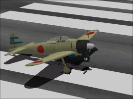
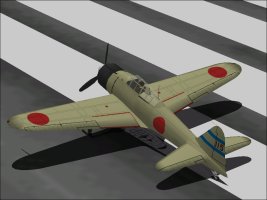
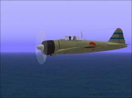
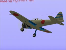
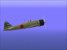
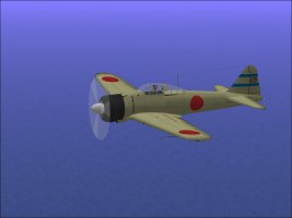
The initial version of my A6M2 Type 0 Fighter was first released back in early 2013.
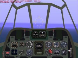
It came with a custom panel derived from a screenshot of a modified virtual cockpit for the aircraft. The virtual cockpit wasn't too bad but was a little too heavy to include as part of the model because of lack of resources but it made a good basis for a panel image.
This was back in 2013 and although I knew what gauges should be on the panel and what they looked like, I did not have the ability to create my own gauges and had to use the closest matching stock gauges.
There were a few other minor problems.
The actual A6M2 Model 21 of the time (1942) could only carry a couple tiny bombs barely worthy of the name. I reflected that in the DP file but of course CFS doesn't really care how big bombs are. They all have the same effect.
After the initial release, I had a few discussions with other CFS people and thought maybe equipping the early A6M2 with a single 250 Kg bomb like the Sen Baku fighter bomber variants from early 1944 wasn't such a bad idea.
The 250 Kg bomb would be an anachronism, but from a load standpoint, it weighed just a few kilograms more than the very common 330 Liter drop tank that the A6M seemed to always carry.
In other words, although I could not simulate the extra fuel capacity or drag of a drop tank, I could simulate the weight of the tank to make carrier and short field take-offs a bit more fun.
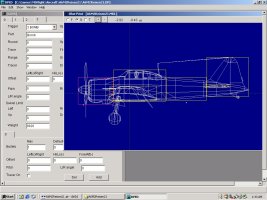
Another nagging little problem was the vertical CoG of the model. Like most people, when I built the first version of the A6M series (A6M5) back in 2002 or so, I started at the easiest place, the propeller spinner. It became the vertical centerline of the model. The problem is that with CFS, the Center of Gravity of the model is the center (0,0,0) of the model itself. There are no offsets in Aircraft.CFG.
On real aircraft, a lot of the heavy items are located below the propeller centerline. Think of Wing Structure, Landing Gear, Wing Guns, Wing Fuel Tanks (even empty), Radiators, etc. That means that the actual CoG of the aircraft probably isn't lined up with the Propeller but considerably below it.
A fair number of things in the model (Parts and Textures) had to be relocated to make this happen. I figured it was good prep for any follow-on versions of the A6M.
Attached is an image of the Wireframe of the A6M2 clearly showing the CoG line below the propeller spinner.
Also shown is the 250 Kg bomb in the DP file.
- Ivan.


Last edited:


