Another "What is it" re Douglas TBD-1

PutPut

Charter Member 2014
OK, what is the lever shown in the 2 attachments for the Douglas TBD-1? I have extensive documentation for this airplane, but this lever is not mentioned. I have accounted for the usual suspects, brakes, flaps cowl flaps, etc. It really reminds me of the clutch lever on my Grandpa's John Deere tractor. It had a lever rather than a foot pedal.

Thanks, Paul


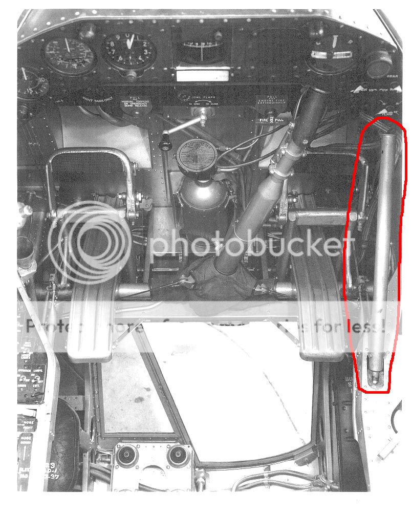
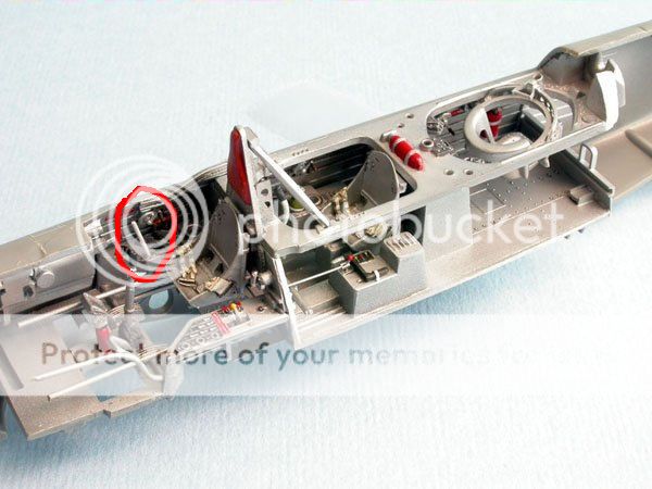
I've looked at this before as well. There isn't a designated landing gear lever or flap lever, is there? Being such an early design, my past thoughts have been that this lever was connected to the hydraulic system, and the pilot had to pump the lever to work the various mechanics that worked off the hydraulic system. I say this, because right next to that pump lever are four separate valves/clutches, one for the landing gear, one for the wing flaps, one for the wing fold, and another I've never been able to make out (though I assume is for the bomb bay doors). Each has neutral positions as well as extend/retract positions. My thought has been that, in order to raise/lower the gear, the pilot had to use the landing gear valve/clutch, put it in the proper selection, and then pump until they were extended or retracted, and the same would go for all of the other hydraulic functions. I have heard it referred to as simply the wing fold hydraulic pump lever, but I think it had to be used for all of the hydraulically controlled functions, not just the wing fold alone, based on the fact that there are valves for each, right next to that lever.

The aircraft is such an early design, it was the first to have hydraulically assisted wing folding, and it came about while retractable landing gear (and flaps) were still much a new thing.
 
My guess is a hand lever for the hydraulic system's pump, similar to the TBM's


TBF_AirTech_4411_DA_hydraulics_p024_W.png
 
Here's a great photo showing some of the details of the other side, and showing no sign of any other lever for any of the hydraulically operated functions (there only being one for the tail wheel lock, the arrestor hook, and a wobble pump for the fuel system):
http://www.modellingnews.gr/sites/default/files/modelling_con_gallery/devastator40_0.jpg

And here is a view of the right, showing the four separate valves I described, right next to the lever (note, in this photo, I can finally easily see that the final fourth valve/clutch lever is for the parking brake):
http://naval.aviation.museum/emuweb...media.php?irn=16028913&size=177x123&image=yes
 
The deciding factor in it all would be if it could be found out whether or not the TBD had an engine-drive hydraulic pump. If it didn't, everything would have to be done by manually pumping that lever (gear extension/retraction, flap extension/retraction, wing fold extension/retraction, and pressurizing the parking brakes (with the valve providing a release)).
 
Howdy All,

According to the 1937 Douglas Pilots handbook pages 6 and 25, it is the hand hydraulic pump.

Right Side Controls.jpg

Hyd Hand Pump Inst.jpg

The TBD is one of my all-time favorite WWII aircraft, let me know if I can help out in any other way!

--Dan
 
Last edited:
Probably the backup hydraulic pump handle... the P40 has engine driven and emergency backup hand pump too....
 
Thanks to all that contributed to this. Clearly, it is a hydraulic hand pump. The right hand cockpit photo posted by John Terrell is one I didn't have and I see I guessed wrong; what I thought was a trim wheel is actually the enclosure handle.

Thanks again (this is what makes this a great forum!)

Paul
 
Do I sense that perhaps someone's thinking about a FSX native Devastator? Something that would look nice when matched with some of our other inter-war and early-war Navy classics?:jump:
 
Back
Top