Experiments to Learn

Ivan

Charter Member
Here is another old project that fits pretty well into the Diversion category.
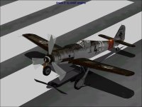
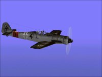
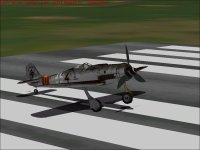
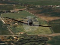
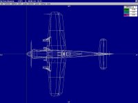
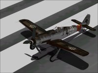
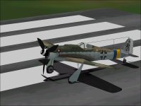
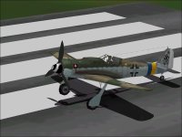
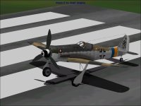
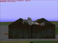
This FW 190D-9 AFX was done by Alex Simon and seems to be the basis for numerous FW 190D and Ta 152 projects out in the CFS menagerie.

This is not the first time I have looked at making corrections to this project.
While the basic appearance of the finished aircraft especially those with textures by Hugh Shoults actually looks pretty good, there are plenty of hidden boogers that are very hard to correct.
From what I can tell, folks working with this project haven't generally tried to make any great corrections to it other than to move the Supercharger Intake from the Port to the Starboard side more typical of a JuMo engine.

As far as I am concerned, this project is pure experimentation and will never lead to a release of any kind.
If I want a FW 190 with an inline engine, it will be a conversion of my own FW 190A project.
At least there, I have a pretty good idea how big the can of worms is before I open the can.

This AFX was done before the rather casual SCASM edits we now throw in without much thought.
There are a few almost hidden parts near the CoG of the Model that are textured to almost provide a virtual cockpit.
I say "almost" because they don't really align with the other pieces of the model but at least they don't leave the model looking like a hollow shell in Quick Combat. Some of the other FW 190D based on this AFX actually use this feature.

Since I know that SCASM works better for the purpose, I decided to remove these pieces.
This brings up another bit of strangeness with this AFX and the zip file containing it.
Although the Assembly had the Parts and they were textured, they did not show as textured in AF99.
Also, the textures that were used by these pieces were not included in the zip file.
I could easily pull them from any number of other FW 190D downloads, but thought it was such a goofy way of doing things, that it was not worth the effort.

I decided to simply remove those pieces from the Assembly.
One might notice in the screenshot that nothing is animated.
This is because in removing those virtual cockpit pieces, the model was changed enough that Aircraft Animator no longer recognizes the pieces it is supposed to animate.

This brings up another point. Has anyone else wondered how Aircraft Animator recognizes pieces that it needs to animate?
I found out a year or two ago that it is actually by the SCASM label for the pieces. (!)
As long as the AF99 edits don't change those labels, prior animated pieces will be recognized (mostly).

So why am I still wasting time on a project that I know will go nowhere?
There are a few things that are done in this project that I never do on my own projects.
I can experiment with those features to see if I can improve them to the point where they become a reasonable thing to add to my own projects. If I fail and damage something, it was a throwaway project anyway and these assemblies tend to be much less complicated than ones in my projects.

It is also very satisfying to make a few simple changes and see some noticeable improvements.

- Ivan.
 

Attachments

  • AlexSimon.jpg
    AlexSimon.jpg
    54.8 KB · Views: 52
Updates and General Experiments

A few additional pieces were added to this model:
Flap Wells, Landing Gear Wells, the Pilot was added a while back.
The Supercharger Intake was also moved to the correct side for a Jumo 213 engine.
The Flaps themselves are a bit more complicated now.
Earlier they were textured the same as the trailing edge of the Wing.
That meant that the inside of each Split Flap was the same as the Wing Upper Surface.
Those surfaces normally don't carry camouflage paint so this was certainly incorrect.

In playing with the propeller animation, I found that this flight model was basically that of a FW 190 with a radial engine.
The Jumo 213A that was developed for the Engine Tuning Tutorial was installed in its place and now I am finding that the Propeller is quite inadequate to handle the level of torque and power that the new engine is giving.

This seems like a good enough model to use to develop a flight model for the FW 190D.

- Ivan.
 

Attachments

  • TestFlight.jpg
    TestFlight.jpg
    29.3 KB · Views: 52
Yesterday, I went into the "Library" and found a couple really good references for the FW 190D-9.
One of the references is in German and my reading is extremely slow.
The other is in Japanese and I can't read that at all.

One had some good dimensional drawings which are almost certainly good enough to convert my FW 190A into a "Dora".
In the drawings, I found that the propeller diameter that I had been using was almost certainly incorrect.
Correcting the diameter actually puts the Propeller Power Coefficient much lower which altered the Idle Speed but didn't change the engine output.
There was other information that needs to be reconciled for the flight model and THAT may mean that the current JuMo 213A-1 needs a slight rework for power levels. It won't change that much, so it makes better sense to do this after a proper propeller with Wide Virtual Blades (Higher Power Coefficient) has been built for this engine.

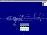
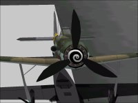
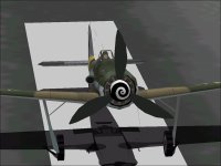
After finding the "correct" Propeller Diameter in the drawings, I noticed that the Propeller Diameter in the visual model was off by slightly over 6 inches. This took about 30 minutes to correct. Perhaps I should check other critical dimensions as well.
The drawings also showed that the piece of armour to protect the pilot's head and back is missing from the model although the headrest and support are present.

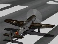
Attached are screenshots of the corrected propeller.

There seems to be a lot of variation in the equipment installed in the Dora-9. Some had outboard wing cannon. Some did not. Some had the ETC 504 weapons rack and some did not. Some were conversions from the A-8 series "Wrack"s and had the earlier non-blown canopy with the older canopy supports and some had the newer solid support more typical of a A-9/F-9 or ground attack birds.

My flight model thus far is somewhat contradictory. It has MW 50 for a power adder but also has the 115 Liter Aft Fuselage Fuel Tank. Either the Water Methanol OR the 115 Liter Fuel Tank could be installed but not both. Since I still plan on using the standard FW 190A Fuel Selector, I may just convert the Aft Tank into the small Priming Fuel tank that was also present. The details still need to be worked out.

That is the reason for working with a throwaway model. All the mistakes get to be made here.

- Ivan.

- Ivan.
 

Attachments

  • CorrectedPropDiameter.jpg
    CorrectedPropDiameter.jpg
    58.4 KB · Views: 0
  • CorrectedPropBlur.jpg
    CorrectedPropBlur.jpg
    72.3 KB · Views: 1
Dimensional Problems

The 6+ inch Propeller diameter discrepancy should have been a pretty good indicator that there might be other issues.
I was about to make some corrections to partitioning of Components in the Fuselage and also add the missing Armour behind the Pilot and decided to do a quick check of overall dimensions. The results were surprising.
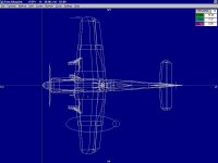
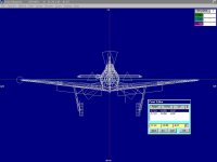
The overall length is 3-4 inches too long, and the wing span is nearly TWO FEET (actually 1.78 feet) too long. This is some of the easiest information to get before starting a project but it doesn't seem like it was ever done here.
Very disappointing.

- Ivan.
 
Partial Fixes

It turns out that the Wing Span was actually 1.80 Feet too long.
I decided to try a fairly low effort fix.
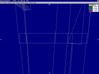
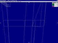
The screenshots show an intermediate stage. (I haven't finished the fixes yet.)

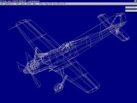
The Wing Tip and Ailerons were combined into a AF99 Component which I called X1.
I then used the CMoveIt (Component Move It) Utility I wrote a few years back to shift the entire Component Inboard by 0.90 feet and Down by 0.07 feet so that the Parts would telescope into the Inboard Wing Section.

The Wing Tip Chord is also a bit too short, so the Wing Tip X1 Component will be slightly magnified (by around 3.5%) to better match the lines of the inboard section.
This won't actually correct all of the size issue of the Wing Tip Chord but it will be closer than it was before.
A proper correction would require a full rebuild of the Wing and I have no intention of putting that much work into this project.

There are also some discussions which suggest that the Overall Length of the FW 190D-9 is actually longer than typically reported.
The length of this model would still be a bit long but is probably not worth fixing.

- Ivan.
 

Attachments

  • TelescopeWing.jpg
    TelescopeWing.jpg
    47.5 KB · Views: 1
  • NewWingSpan.jpg
    NewWingSpan.jpg
    42.9 KB · Views: 1
  • Mismatch.jpg
    Mismatch.jpg
    37.9 KB · Views: 3
Corrected Wings

The Wing Tip and Aileron (combined into Component X1) was stretched Longitudinally by a factor of 1.032.
There were no changes in Vertical or Lateral dimensions. After that, the adjusted X1 Component was moved to match the inboard Wing section.
This was a very simple process using command line utilities once the degree of adjustment was determined for each stretch or shift.
After that, a reference Part was created from the end of the Wing inboard section and Wing Tip and then a Station Template was created which was the average of those two Parts.
Once the Parts of each Wing Component were adjusted to match the new Station Template, the task was basically done except for moving the Pitot Tube to match the new Wing Tip. A bit more measuring, three calls to utilities and that task was also done.

Texturing for this model is extremely basic and was not hard to correct. It still is not optimal, but is no worse now than it was before except that the crosses on the Wings are very slightly more distorted.

- Ivan.
 

Attachments

  • Stretch1032.jpg
    Stretch1032.jpg
    37.4 KB · Views: 0
  • CorrectedWings.jpg
    CorrectedWings.jpg
    44.3 KB · Views: 0
  • Fixed Wings.jpg
    Fixed Wings.jpg
    53.6 KB · Views: 0
Center of Gravity Shift

One of the odd things about this project is that the Center of the Model is at the tip of the Spinner.
This can be seen in some of the prior screenshots from AF99.
The odd location is corrected by a shift of the Center of Rotation by 9.9 Feet.

Personally I do not like this arrangement. I prefer to have a Model built with minimal (or ideally no) shifts.
This seemed like the perfect opportunity to use the tools that I programmed when working on the Eric Johnson P-39D.
Things went off without a hitch..... Almost.

It seems that many of the Parts files in this project have rather long names with embedded spaces.
This obviously causes some problems with utilities that operate on command line parameters.
It took about an hour longer to work around that problem. (About 3 failures before finding a solution)
The old animated pieces were still recognized when going through Aircraft Animator, so very little additional work was needed.

Last night was also the first time I took Dora up for a general test flight.
The impression was not so good.
While the Aeroplane has a pretty large surplus of power and some serious engine torque as expected, general maneuverability and handling is extremely poor. Roll rate is pretty average.
While the Dora was known to be less maneuverable than the earlier radial powered Aeroplanes, this wasn't just a little worse, it was simply bad.

I am not about to throw out this AIR file just yet. It is still interesting to see how and where it can be fixed.

- Ivan.
 

Attachments

  • ShiftedCG.jpg
    ShiftedCG.jpg
    47.1 KB · Views: 1
  • ShiftedCG&Paint.jpg
    ShiftedCG&Paint.jpg
    56.5 KB · Views: 0
JG57 Dora-13

Many many years ago, I worked on a few projects with the crew of JG57.
I was never a formal member. I have an aversion to committing to organizations but there were several of their aeroplanes I was involved in doing mostly visual model adjustments with.

I don't believe their FW 190D-13 was one of them but I thought this was a pretty good opportunity to make a few corrections to an aeroplane with a few features that have always bothered me a bit.
With the edits to Alex Simon's FW 190D-9 that have already been done, most of the fixes are already in place.

The first step was to see how well the textures of the Dora-13 would map to the Dora-9.
The first screenshot shows the original JG 57 FW 190D-13.
The second screenshot shows the textures mapping directly to the modified Alex Simon FW 190D-9 without modification.
The mapping order was quite a bit different but that was no surprise.

The JG 57 Bird probably still retains the attempt at a virtual cockpit that is sitting inside the Fuselage center at 9.9 Feet behind the Spinner Tip.
I removed that in modifying the D-9.
The D-13 also has a textured rotating Propeller Blur.
I use a different method of representing the Propeller Blur in my version and it doesn't use a texture file.
The D-13 doesn't have a Pilot.
One of my changes was to add the Pilot from one of my P-40's to this project. He didn't really want to take on the task so he still wears his old AVG Leather Jacket.

Without any additional work, the following items were corrected:
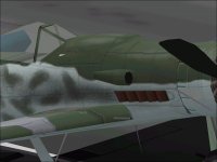
The Landing Gear Braces no longer bleed through the Wings and Fuselage from odd angles.
The rather odd bleed at the upper Nose of the Aeroplane has gone away.
The Coolant Radiator is no longer rotating.
The Propeller Diameter is now 3.500 Meters instead of a bit over 12 Feet as in the earlier model.
(In reality to be completely correct, the Propeller of this model will need to be adjusted to 3.600 Meters Diameter or a bit over 11.81 Feet because the later Dora-12 and Dora-13 used a different model Propeller and Spinner.)

I haven't done any significant reworking of the AIR file of the Dora-13 but was noticing that the weight was way way too low.
I figure it was off by around 700+ Pounds. A quick and not particularly accurate correction was made to see if it would correct a strange tendency to pitch down.

Up to this point, I had not really looked at the DP files of either the D-9 or D-13.
In looking at the D-13, I found some serious strangeness.

First of all a little background may be in order:
The Dora-9 originally started with pretty much the same armament as a FW 190A-8 with 2 x MG 131 Cowl MG and 2 x MG 151/20 in Wing inboard positions and 2 x MG 151/20 in the Wing outboard positions.
With the same armament, the Dora-9 was considerably heavier than the A-8 and A-9 because the Jumo 213 was a much heavier engine /radiator combination.
Later Dora-9 had the outer wing cannon deleted.
This change made the Dora-9 about 100-130 KG lighter than the late model A-8.

The Dora-12 was intended to be the next production model.
It had a two stage supercharger in the Jumo 213F and a revised Propeller Pitch change mechanism that allowed installation of a Motor Cannon. (The earlier 213A had oil lines running through the bore of the Propeller Shaft.)
The two Cowl MG were removed and a MK 108 was installed firing through the Propeller.

The Dora-12 never reached production because of shortages of he MK 108 30 mm cannon.
Instead, the Dora-13 was designed with a third MG 151/20 mounted as a Motor Cannon with 220 rounds of ammunition.

In checking out the DP, I found that the locations of the guns on the D-13 were way too far forward and that although the description in the AIR file correctly specified a 20 mm MG 151 Motor Cannon, the DP file used a 30 mm MK 108.

I never had a chance to test fly after making these adjustments, but I suspect that shifted a few hundred pounds of ammunition about 7 Feet aft should cure the pitch down tendency.

- Ivan.
 

Attachments

  • JG57_D13_Original.jpg
    JG57_D13_Original.jpg
    55.2 KB · Views: 2
  • JG57_D13_Updated.jpg
    JG57_D13_Updated.jpg
    55.4 KB · Views: 3
  • AftDeckBleed.jpg
    AftDeckBleed.jpg
    42.8 KB · Views: 2
  • BleedPossiblyFixed.jpg
    BleedPossiblyFixed.jpg
    44.9 KB · Views: 2
Dora-13 Updates

The FW 190D-13 had a slight remodel over the last day or so.
The Propeller is now the VS-9 version with a diameter of 3.600 Meters.
The Engine is still the not-quite-correct Jumo 213A power range though.

My original weight estimate turned out to be about 110 Pounds too high if the Zero Fuel Weight is calculated with only a half load of MW50. If it is calculated with a full load, it is about 50 pounds too low, so it was definitely in the correct range.

The Spinner is now a touch shorter for the cannon blast tube.
Even with the shorter Spinner, the D-13 with its updated Supercharger was 4 mm longer in OAL.
It is not reflected in this model. It is slightly shorter than the model of the D-9 though it is probably longer than the actual aircraft.

Reshaping the upper Nose / Fuselage area was a bit tougher than expected. The naming of Parts was very strange and unpredictable. Of course when one has their own system, every other Designer's naming convention is just wrong.....

I believe this is a pretty serious improvement in appearance over the original.
Now we just have to work on the flight performance which was the main objective of this project.

- Ivan.
 

Attachments

  • D13.jpg
    D13.jpg
    56.7 KB · Views: 51
Instrument Panel

As part of the experiments, I thought it would be worthwhile to edit a proper Panel for the Dora.
The panel from the stock FW 190A seemed to be a good start.

To be honest, I had never really taken a good look at this panel other than for aesthetics.
When I was doing development work on the flight models, I was using a Test Panel.
When I assembled the package, I just presumed that MS had done things more or less correctly.
My old Development Computer also didn't really allow me to fly with the control panels being displayed because of the serious frame rate hit. In testing, it wasn't so much of an issue because the numbers being displayed were more important than the stuff in the background.

For the FW 190D, I figured I would just take the stock FW 190A panel and add a Trim Gauge, add a Magneto Switch which for some reason is missing and swap the Cylinder Head Temperature Gauge for a Coolant Temperature Gauge.
Surprisingly, there isn't a CHT Gauge on the panel at all.

Regarding the missing gauges:
The FW 190A actually did have both a Magneto Switch and a CHT gauge, so I am not quite sure why they were left off the stock panel.
The Magneto Switch is located on the forward part of the Left console.
The CHT gauge is on the lower row of gauges and slightly to the left.

Borrowing a Mag switch from the stock Messerschmitt is pretty easy.
Programming a CHT gauge probably isn't hard, but I have yet to find a good image of what the face of the German gauge looks like.

- Ivan.
 

Attachments

  • FW190A_Panel.jpg
    FW190A_Panel.jpg
    87 KB · Views: 51
Regarding the poor handling of the D-9, I believe I finally figured out the reason.
The AIR file is straight from the Engine Tuning Tutorial.
The only goal of that AIR file was to get Engine Output that was reasonable for a JuMo 213A.
The problem was that I used the stock FW190A AIR file as a starting point.
When the testing is all done by autopilot and maneuverability is never tested, the issues with the stock FW190A never showed themselves as they are doing now in lack of roll, poor maneuverability and problems with maximum speed runs under autopilot.

It seems like the current AIR file is really a throwaway. There are too many things to correct and it makes more sense to just transfer the engine parameters to something better such as the FW 190A-8/R11 AIR file that is also in development.
It isn't well tested either but shows much more promise than the stock FW190A.

- Ivan.
 
Hello Rince33,

Thanks for the link to the video. It was quite educational.
There are a bunch of characteristics mentioned that I KNOW I can't duplicate in CFS, but it is nice knowing they are there.
The lack of engine torque on take-off is surprising with the amount of power and size of propeller.

I can take no credit for the panel. It is the stock FW190A panel with a couple additional or substituted gauges.

- Ivan.
 
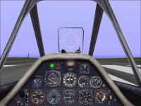
This is an image of the updated panel.
Note that there is now a Magneto Switch on the lower left by the Flap control and Ignition Switch.
There is also a Radiator Temperature gauge that now sits where the Fuel Gauge was before.
The Fuel Gauge has been moved to the lower right corner.
The panel is kind of cramped for space, but functional.

The panel still isn't quite done. It needs a new Fuel Selector that only has two tanks.
Most Doras had only two fuel tanks with a MW50 tank.

- Ivan.
 

Attachments

  • Dora_Panel.jpg
    Dora_Panel.jpg
    87.8 KB · Views: 36
The Flight Model is now a copy of my FW 190A-8 with edits to suit the different 3D Model and of course changes to address the JuMo 213A Engine in place of the BMW 801D-2.

Specifically after copying the AIR file from the A-8, the following Records were replaced:

301 - For Cockpit View and Loading into the Simulator
500 - Engine
505 - CFS Engine
506 - Engine related
507 - Engine related
508 - Engine related
509 - Engine related
510 - Propeller
1004 - Landing Gear

After these edits, the handling is pretty much that of the A-8 but with the power of the D-9.
In reality, there are quite a few more edits required, but this takes care of the basics for handling.
Straight line performance is another story.

The new FW Fuel Selector Gauge set was also completed yesterday.
Record 535 - Center3 Fuel Tank was removed. Most Dora did not have the Fuselage fuel tank. They had a MW50 tank in that location. The new Fuel Selector only has two positions for the Center1 and Center2 fuel tanks.

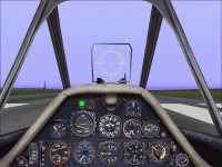
The first screenshot shows the new panel arrangement in flight.
I chose to put the Fuel Gauge back to its original size and location to be easier to read.
The Radiator Gauge on the extreme right is obviously functional at this point.
The Tachometer shows around 3250 RPM which shows without a doubt that the engine is NOT a BMW radial.

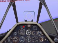
The second screenshot gives an idea of level of agility of this bird.
It is still not a lightweight though, so there are plenty of ways to get killed without help.

On a side note, substituting the records from the D-9 into the A-8 AIR file only took about 5 minutes.
The utilities I wrote for working with Propeller Tables worked pretty well for this purpose.
Still plenty left to do though.

- Ivan.
 

Attachments

  • UpdatedDoraPanel.jpg
    UpdatedDoraPanel.jpg
    91.6 KB · Views: 2
  • ChasingBuildings.jpg
    ChasingBuildings.jpg
    37.6 KB · Views: 2
Edits to Visual Model

I have always stated that there were many shape problems with this particular 3D model and that I only intend to fix the worst of them.

One of the very noticeable things about this series of models is that the slab of armour plate behind the pilot's head and shoulders is missing. From an exterior view it is not that conspicuous, but from a cockpit view, it is very obvious. I could of course add it only as a part of the SCASM virtual cockpit, but I don't believe that is the best way to handle the problem.

Adding the armour plate wasn't difficult but to make it fit in with the headrest behind the pilot meant that the shape was quite strange. The headrest is a continuation of the rear of the canopy and this wasn't the ideal way to do things.
I will have to go back and make some edits to the headrest so that the pieces are shaped less strangely. The Armour Plate should also be textured, but that increases the likelihood that the animation will be affected and I do not want to redo the animation.

The other thing that was done last night was to make some minor adjustments to the AIR file.
I was a bit less than prepared and didn't actually have a data sheet to work from.

The Scrape Points between the D-9 and A-8 do not differ in a meaningful way, but they did need to be confirmed.
The Engine / Propeller location needed to be moved forward several inches as expected.
The Tail Surfaces should also be moved aft but I need to either gather some proper data or scale dimensions from a less than accurate model.

- Ivan.
 
Tuning Engine Power

I went back through the Engine Tuning Tutorial and realized that I had actually substituted the Propeller Tables, 511 and 512 from the stock Me109G so that was done last night.

The first instrumented test was quite interesting: The manifold pressure was correct but the engine power was in the 2100 HP range instead of the 1661 HP as expected.
In comparing what I had to the original Engine Tuning AIR file, I found that two of the Records that I thought I had copied did not seem to have worked, They were the Friction and Torque Records. Once those were corrected, everything was fine from a Horsepower standpoint.

This is rather strange. The record copying utility worked fine on much more complicated records.
This may have been because I batched a few and might have screwed up in the actual calls to the utilities.

The Power versus Altitude pretty much matched what was gotten from the Tutorial.
The first speed run showed that the new FW 190D was about 10 MPH slower at Sea Level and about 20 MPH slower at altitude.
A comparison of the Zero Lift Drag showed why.
The Tutorial AIR file was based on the stock P51D. CD0 was 0.01907
The new AIR file is based on a FW190A. CD0 was 0.02295
The FW190D was a bit more sleek than the FW190A, but I don't think the difference was really that great.

The other thing that was changed was that the weight was increased to 8028 pounds.
This includes a half load of MW50 in the Zero Fuel weight. The FW 190D was actually a heavier aircraft but only ends up lighter in gross weight because it doesn't carry the two outboard MG 151/20 and their ammunition.
The calculation for weight will be shown in a future post.

That correction was made and I now have an AIR file that should be near identical to the Tutorial file at least from a performance standpoint. In detail, it is VERY different. That does not mean it is really accurate though, but it may be good enough for the POC model I intend to use it on.

Proper fine tuning will take a while.

- Ivan.
 
Zero Fuel Weight

The loaded / Take-Off weight I will be using to calculate the "Zero Fuel Weight" for the FW 190D-9 will be 4293 Kg.
Some sources list the loaded weight as only 4270 Kg but this is apparently for early aircraft that were not equipped with MW50.
The Luftwaffe data tables for the type list it as 4300 Kg which is pretty close and a bit under the 4350 Kg that is typical for the FW 190A-8.

As I may have mentioned before, the Jumo 213A installation with cooling system was a bit heavier than the BMW 801D that it replaced but the difference was more than made up by deleting the two outboard wing cannon.

9364 Pounds - Loaded Weight (4293 Kg)

178.57 Pounds - 950 Rounds MG 131 Ammunition
242.51 Pounds - 500 Rounds MG 151/20 Ammunition

369.3 Pounds - 233 Liters Fuel (Forward Tank)
462.8 Pounds - 292 Liters Fuel (Aft Tank)

97.16 Pounds - 49 Liters Engine Oil

236.6 Pounds - 115 Liters MW50

To calculate Zero Fuel Weight for the AIR file, we will take the loaded weight and deduct the following:
Ammunition Weight
Fuel Weight
1/3 of the Weight of Engine Oil
1/2 of the Weight of MW50

Result is 8028 Pounds.
This is about 330 Pounds heavier than for the FW 190A-8 but note that this includes half a tank of MW50.

- Ivan.
 
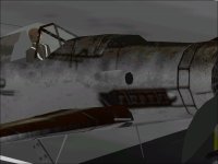
This is a comparison of the appearance of the cockpit area before and after adding the armour plate behind the pilot.
The modifications to the shape of the headrest to fit entirely behind the armour are not apparent in these screenshots.
It may not be entirely obvious but the texturing (but not the strange mapping) of the headrest has been altered slightly.
It no longer shows the light spots that were apparent in earlier screenshots.

At some point, I may need to go into the AFA file and rename all the current texture files for more consistency. Spaces and variable length names are hard to work with and do not work with AF5Paint. I will also need to add one more texture file and this project already uses 13 in a rather inefficient manner:
Certain details such as wheels and wheel wells take up a very large space. Others such as the major parts of the fuselage are compressed into one texture file.

- Ivan.
 

Attachments

  • Headrest_NoArmour.jpg
    Headrest_NoArmour.jpg
    43.7 KB · Views: 2
  • CockpitArmour_ExteriorView.jpg
    CockpitArmour_ExteriorView.jpg
    46.2 KB · Views: 2
  • CockpitArmourPlate.jpg
    CockpitArmourPlate.jpg
    78.5 KB · Views: 2
A most interesting thesis Ivan and a brilliant read.

I only wish I could understand it!!

Don't stop until it behaves as you want it to.

Best wishes, Graham.
 
Back
Top