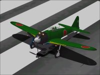
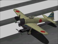
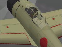
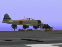
The Mitsubishi A6M5 was one of my earliest design projects for Combat Flight Simulator.
It was first built in late 2001 when I was very inexperienced in making choices and gathering information for a project.
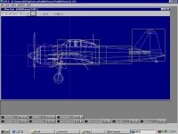
The source for the drawings was one of the books by William Green.
For those who are not familiar with these books, the illustrations about the same quality as a typical painting.
These days, I would never start a project without a "reasonably accurate" set of drawings, but back then, I didn't know any better and of course, there was the urge to get a completed aeroplane in the simulator as quickly as possible.
Unlike some of the other illustrations, the one for the A6M5 turned out to be fairly good though over the years, I have made quite a few detail corrections to the original design as I added new features. The greatest number of changes was done when the original A6M5 was modified into a A6M2 Model 21 a few years ago.
When this modification was made, there were several things that bothered me about the design but I did not have the knowledge to address them at the time.
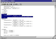
The first, which was addressed about a week ago and is the subject of this thread, was that the Vertical Center of the visual model was located too high. At the time I started working on the model, the idea of properly locating the Horizontal Center of the model was something that was pretty obvious but the Vertical Center of Gravity of aircraft is not often discussed and very seldom found in documentation. Without knowing any better, the obvious centerline would seem to be through the thrust line / propeller shaft of a Radial Engine and that is what I used.
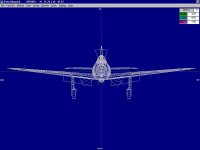
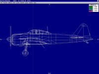
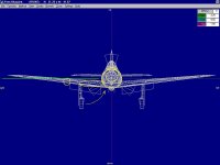
The two attached screenshots show the front and side views of the A6M2 with the vertical center line through the spinner.
-------

