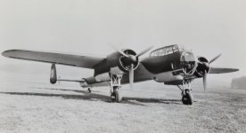
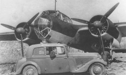
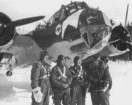
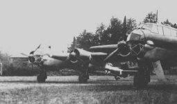
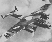
Project Dornier Do-17z2

aleatorylamp

Charter Member
Hello folks!
Well, after an inactive Christmas spell of overeating and generally doing as little as possible, I´ve decided to make a nice Dornier Do-17, which will hopefully be nicer than the stock AI version! Smilo also wants a nicer one, so all the more reason to do it!
Early Do-17 versions had 1000 Hp Bramo Fafnir 323 engines with single-speed superchargers, which gave only 900 Hp at S.L., but the Do-17z2 had the superior Bramo Fafnir 323P, with a 2-speed supercharger, making the full 1000 Hp were available at S.L.

Performance specifications of the real Dornier Do-17z2: (Note: Speed and power together are only given for S.L.)
> Sea level: 1000 Hp and 217 mph.
> 10200 ft: 1000 Hp.
> 13200 ft: 940 Hp.
> 16400 ft: 255 mph.

Work on the stock AI Do-17z2 Air file, which had far too much power and speed all round, so a lot of adjusting had to be done:
a) corrected cylinder displacement and RPM values
b) tweaked torque and friction graphs
c) considerably reduced Boost Gain value
d) adjusted drag values

Model Performance: (Maybe Ivan can give his always very much valued opinion here!)
> Sea level: 1003 Hp and 221 mph. (slightly fast)
> 10200 ft: 1071 Hp and 250 mph.
> 13200 ft: 940 Hp and 246 mph.
> 16400 ft: 813 Hp abd 244 mph. (a bit slow)

Generally seen, this performance looks quite acceptable, but I wonder what Ivan´s opinion would be! Only if you have time, Ivan, and are not too busy to answer or stressed out, of course!

Cheers and a Happy 2017 to all!
Aleatorylamp
 

Attachments

  • Dornier_Do_17_Z-2.jpg
    Dornier_Do_17_Z-2.jpg
    91 KB · Views: 5
Supercharger Critical Altitude and Max. Manifold pressure?

Hello again!
Looking further into the engine parameters on the AI Do-17 .air file, I noticed Max. Manifold Pressure very high at 60.445, and also Critical altitude at 22400 ft. This would more likely fit a late WW2 supercharger!

Looking into other early WW2 models , it would be more realistic around perhaps 42 for Max MP and 17000 ft for critical altitude, and as I can´t find the values for the Bramo Fafnir Superchargers anywhere, this educated guess is for the moment the only solution. Of course, changing Max MP and CA requires changing some other parameters, but that will be no problem.

The first trials in this sense seem to provide similar engine and aircraft performance results as the first tests, but we shall see!

Cheers,
Aleatorylamp
 
Slight adjustments

Hello folks!
Further research from a German page on the Bramo Fafnir engine has revealed a few more exact details:
The improved 940 Hp at altitude of the 323P engine were achieved at 15000 ft, and not at 13200 as I´d mentioned before. Also, Critical Altitude is confirmed at 10200 ft, upto where full 1000 horsepower could be maintained.

Trials with Maximum MP at 44 Hg and Boost Gain at 2.286, gave the following performance:
>Sea level:228.0 mph, 1003 Hp, 44.0 Hg (virtually correct power, but 14 mph fast, needed to maintain altitude performance)
>10200 ft: 259.3 mph, 1095 Hp, 44.0 Hg (inevitable Critical Altitude peak here: +95 Hp power and at least +4.3 mph)
>15000 ft: 247.0 mph, 940 Hp, 37.6 Hg (exactly as per specified power)
>16400 ft: 255.7 mph, 887 Hp, 35.6 Hg (exactly as per specified speed)

Ceiling is stated at 27000 ft. Here power goes way down to 513 Hp, and the aircraft just about maintains RoC at 100 fpm.

So, I´d say these more realistic Max. Manifold Pressure, Critical Altitude and Boost Gain settings now give somewhat better results. Any ideas and suggestions would of course, as always, be very welcome!

Now the building starts. As soon as I have a nice Kindergarten colourful cardboard model ready, done in 2D templates, I´ll post it together with the .air file, so that anyone who´s interested can try it out.

Cheers,
Aleatorylamp
 
More interesting details

Hello again!
As usual in these cases, interesting additional details crop up on more-difficult-to-find sites :eek-new:. I´ve just found three that state Vmax for the Do-17z2 with the 323P as being 163 and/or 165 mph because of the superior supercharger, which is 8-10 mph faster than the previous sites, but without an altitude reference.

Now, what has to be decided, is what information is more reliable
:indecisiveness:! Perhaps this piece of information fits in nicely to account for the Critical Altitude peak, which at the moment is around 160 mph, so only slight re-adjustment will be needed :cool-new:.

Update: Closer inspection of the power curve reveals that the current FD peak is in reality a little higher than I thought, at 10800 ft, with 1104 Hp giving 263.5 mph.
A slight increase in Boost Gain from 2.286 to 2.33 only moves the peak upwards to 11600 ft with 1104 Hp giving 265.2 mph, but leaves performance at 10200 ft the same as before, so I shall leave Boost Gain as it was, at 2.286
:calm:.

Ivan, I know you were working on a Do-17z2 experiment as well, and I´m curious as regards the performance specifications you were striving for, if you have time and were to be willing to share the info!

Cheers,

Aleatorylamp ....................... P.S.: Merry 3 Kings´Day!! Even more presents!!
 
Last edited:
Hello All!
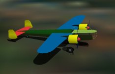
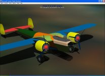
I´ve started with the basic layout of the model, and haven´t really done a 2D cardboard model by any means - the only 2d things are the wings and tail, and, I´m running into complications with the fuselage: It´s not at all the usual rounded square or circular cross-sections job with wing-root skirtings! The only straight forward things are forward engine nacelles, wing, and tail empenage!

The main body of the plane looks like a much more modern design, quite ahead of its time. Cross sections are very unorthodox, especially at the wing root, all a smooth flow of gentle curves and slanted sides with very rounded edges. I now remember Ivan had mentioned this rather complicated aspect, which will take some thought as regards the best way to approach the matter.

At first I was thinking "Piece of cake! Structures for the fuselage except for glass areas: Keystone bulkhead for lower fuselage and dome bulkhead for the upper part!" But no way! It´s mostly going to have to be special components, except perhaps for the rear fuselage, which may be able to handle these structures.
Anyway, we shall see!
Cheers!

Aleatorylamp
 

Attachments

  • Dornier1.jpg
    Dornier1.jpg
    26.8 KB · Views: 6
Reply...

Stephan,

Do these screenshots help as far as the shape is concerned?
 
Hello Aleatorylamp, Rami,

Sorry I haven't had a chance to respond to many threads lately.
I / we have ad lots of things going on for the last few weeks and it is likely to continue for about another month or so.... Hopefully with good outcomes for all involved.

Regarding the AIR file for the Dornier 17Z-2, I never actually built one for my model.
I knew the model was going to be the difficult area and just used a converted Mitchell C AIR file for testing / viewing purposes.

As for the model, Aleatorylamp, you are finally starting to understand why this is a difficult subject to do well. EVERYTHING on this bird is a complex curve except for the Tail, Engine Cowls and Wing Tips.

The part that got me stuck was the rear of the Nacelles / Flap interaction.
I CAN handle it via SCASM, but it is still pretty complicated.

Another very difficult area is where the Canopy Glass and Framing interact with the Wing Root extensions. It IS possible to do without bleeds but is very resource expensive and takes this project (for me) way past what I can do without SCASM.

You will certainly find out more as the project progresses.

Rami,
Your model looks quite nice but does have some simplifications over the real aeroplane. There are plenty of videos of this bird still available which give a better idea of its shape. It is a very hard one to capture correctly and 2D drawings only give the basic outline.

Take Care.
- Ivan.

P.S. I will post some screenshots to show where I reached if I have the time to get into my development machine and it stays running long enough.
 
Hello Rami,
Thanks for the screenshots! The shapes shown look reasonable. I found some diagrams containing a sequence of 7 very difficult looking fuselage cross section details. The screenshots certainly show possibile shape solutions.

Hello Ivan,
Thanks for your post, and I hope you are getting good results from all that you have to do!
Your comments on the difficulties involved with the shapes are quite to the point!
I was just thinking about the rear upper cabin area with the shoulderwing. It´s completely flat there!

The extreme rear of the engine nacelles you mention had a small section that tucked in to make room for the flap deflection! Complicated indeed! ... and I´m not progressing. Also dire, are the wing-root leading and trailing edges, as well as the upwards and downwards bulging cabin!

Difficult, isn´t it! Not a piece of cake by any means. Now I know why there isn´t a better Do-17 other than the AI one!! Ha ha.
So far, the only sense of achievement that I got is from the performance adjustments in the .air file. I wonder...

Well, I´ll continue experimenting a bit and see if there´s a possible, plausible and elegant looking way around all this shape complication! I´ll try my hand at shaping the wing root into the aft-cabin fuselage component. A kind of mono-coque section is out of the question because of the under-wing concavity, so it will need at least 3 components there. Let´s see how it goes...

Cheers,
Aleatorylamp
 
Fuselage and wing root progressing

Hello!
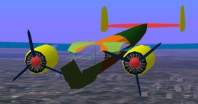
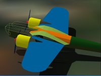
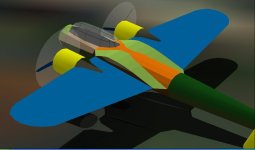
I used a shoulder component for the fuselage around the rear cabin, hollowing out for the wing-root, and it seems to work.
(As yet, inner wings are 2D, and the fuselage belly is still trapezoid - will be more rounded though).

Here are some screenshots. Of course, a different matter will be once the cabinglass parts are placed, but that is for another day.

Cheers,
Aleatorylamp
 

Attachments

  • Midfuselage front.jpg
    Midfuselage front.jpg
    48.6 KB · Views: 1
  • Midfuselage top.jpg
    Midfuselage top.jpg
    37.1 KB · Views: 1

Hello Smilo,
Thanks for your good words!
I got a bit further last night - here´s another screenshot.

To avoid what Ivan mentioned about aft-cabin interaction with forward wing-root parts, I put the upper cabin-glass and canopy-frame into Canopy/High Wing ("lid" and antenna mast are still missing!)This gets the cabin out of the way and AF99 automatic glue seems good enough.

Then, despite the necessary simplification of making the wing-root leading and trailing edge curves straight (concavities are impossible), I think it´s getting the look!
Cheers,
Aleatorylamp
 

Attachments

  • a bit further.jpg
    a bit further.jpg
    47 KB · Views: 5
agreed...it is getting the look.
and i like it!

far be it for me to quibble
over straightened trailing and leading edge curves.
especially, if they are impossible to build.
perhaps with ad2k, but, you're not using ad2k.
are you?

i've always thought it rather odd,
that cfs1, a sim with such a large portion
dedicated to the battle of briton,
would have such an inferior representation
of a major player in the battle.
thank you for putting forth the effort,
to build this long over due cfs aircraft.
 
Hello Smilo!
Thanks for your interest indeed!
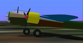
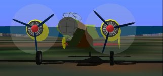
I´ve just finished strutting out and glazing the front, and I´ve corrected a few things on the side panels.
For the moment, the interior is not hollow, and I´m trying out different things here and there to get it as best as popssible, but it´s coming along quite OK. At least I´m not stuck! Here are another 2 screenshots.


I use AF99 because I can understand it better - I tried AD2k2 a while back (no bleedthroughavoidance sequencing), and would use AD2k for CFS1, but amongst other things, the sequencing I found was a bit complicated, so I´m sticking with AF99.
Upto now, with the models I´ve been building over the years, I´ve managed to get around most of the problems one way or another.

Cheers,
Aleatorylamp
 

Attachments

  • more progress1.jpg
    more progress1.jpg
    29 KB · Views: 5
first and foremost, let me make it clear,
i am not pushing ad2k.
i only built one model
and that was years ago.
i completely understand what you say
about sequencing being "a bit complicated".
if anything, that's an understatement.

that said, once the sequencing is sussed out,
(which in my case, required excessive patience)
ad2k offers a much more complex model.
so complex, the model might even be
a resource hog on older computers.

as i've said before,
i've considered picking it up again,
but, realistically, am not sure
if i have the time or energy
to devote another year to a project.

in the mean time,
i'll sit back and enjoy watching you
build an aircraft i've wanted to see
for the past, nearly, 20 years.
 

Attachments

  • dornier17.jpg
    dornier17.jpg
    17.8 KB · Views: 4
Hello Aleatorylamp, Smilo,

Smilo,
I am glad you are finally getting the Dornier 17Z that you wanted.
I also had a quick visit to AD2K a couple years ago.
In fact, I have it installed on my current laptop even though I do not have CFS installed.
It does obviously offer serious additional capability though I have so much invested in AF99 models, I should finish a few first.
My goal is usually learning something from each project and at the moment, the topics are gauges and panels and AIR files rather than visual models though I get bothered a lot by the AF99 limitations.

When Aleatorylamp asked about what I had used for an AIR file for my Dornier 17Z project, it shocked me to realise how little research I had actually done for the flight model.
Since then, I decided to poke around a bit and see what I could actually find and the results are interesting.
As I mentioned in the beginning, I didn't have a great interest in the Dornier 17Z because at best it was only a mediocre performer which is one reason it had so little success.
What I did not expect to find was that its near twin, the Dornier 215, was a much better performer at almost 300 MPH.
Apparently the BraMo Fafnir was a serious performance limit though it was apparently quite reliable.
The only things I am still looking for as far as AIR file data are the Propeller Pitch range and the Weight Breakdown to get a Basic Weight value.
If it were not for Aleatorylamp's project, I probably would not have looked any further.

Aleatorylamp,
Your project looks like it is coming along quite well. It definitely has a better shape than others I have seen.
Since you are currently on the Canopy framing, please note that the front of the Canopy is slightly asymmetrical.
This was the last thing I was working on for my version. I miscounted the number of frames which got me very frustrated at the time.
The other thing worth mentioning is that the Nose Glazing is slightly asymmetrical as well in a bit more subtle fashion than the Canopy.

By the way, it isn't impossible to build a concave Component in AF99. There are limits, but the Wing Roots should work well enough.
I actually did build the curves into my version if I remember right.

Better sign off now. I have perhaps 15 minutes before Anna Honey and I leave for the next event tonight.
Needless to say, there has been no progress on the BV 141 over the last few weeks.

- Ivan.
 
Hello Smilo,
Ha, ha! Good man! I´m glad you are watching.

I´ve finished the forward and upper glass, and starting on the lower rear glass.

At the moment I´m working on a Win 8.1 laptop with virtualized Windows XP, and everything works except the CFS1 hardware accelleration, (graphic accellerators seem to fall short with OS virtualization programmes, and CFS1 won´t work at all with this laptop and Win8.1), so the screenshots are ugly, but I´ll send a screenshot from the XP tower tomorrow - there everything works perfectly!

I know you aren´t pushing AD2k. Yes, AF99 models are simpler, but that´s also why it´s faster to build with.

Anyway, let´s see if the muses help and I am able to get a decent Do-17 out! 20 years... a long wait!

I´ll use the livery of the one in the picture you posted!

Hello Ivan,
Thanks for your moral support!
I believe the models with the assymetrical canopies were variants of the glazed versions prior to the Z2 variant, but I´ll check again. Those also had the less powerful engines with 100 Hp less at sea level.

Cheers,
Aleatorylamp
 
Hello again,
I also saw that the older version of the Do-17 without the bulging glazed nose, had a very assymetrical canopy too. There were a number of these that went into the Spanish Civil War. From what I´ve seen, the later Z editions were symmetrical - but of course, I could be wrong.

Anyway, I couldn´t stop myself and I dashed to the XP tower. Here are some screenshots!
The lower front still hasn´t got the grey bulkhead to block off the fuselage transparency like the upper front. I also managed to round off the nose fuselage area between the glass nose and the windshield. Parts count is at 78.3 at the moment.

I´ve never made a plane with so many window struts and window panes!! Only the forward and upper strutting and glazing take up 17.3% parts! Hmmm... I just noticed that perhaps the window struts are a bit too narrow...

Cheers,
Aleatorylamp
 

Attachments

  • progress1.jpg
    progress1.jpg
    32.1 KB · Views: 0
  • Progress3.jpg
    Progress3.jpg
    34.9 KB · Views: 0
Hello Aleatorylamp,

If you look carefully, there are actually several distinct asymmetrical areas on the Do 17Z series (not the Kauz II Night fighters which had a different nose). I have noticed three but perhaps there are more.
Do not trust all the drawings out there. Some such as found on Wikipedia are simply wrong in detail.
The only significant difference between the Z-1 and Z-2 is the engine model. Z-1 had BraMo 323A. Z-2 and later had the BraMo 323P. 323A is a single speed supercharger, 323P is a two speed. Both are single stage and rated altitudes are quite low.
Did you ever find a good number for propeller pitch range? I will be trying more when I have the time.

Regarding Canopy Frames and Glass, the BV 141 series has these aeroplanes beat by a lot and even the A6M Type Zero is pretty close. The part that was throwing me off was that the shapes are not very regular and have to match a constantly changing cross section which meant that logical separation lines of the Fuselage and Canopy often did not match.

Screenshots look pretty good so far.

- Ivan.
 
Hello Ivan,
Thanks again for your input and counsel!

.air file and model performance:
Attached herewith is the .air file I´m using, if you want to try it out.
I adapted the engine and drag parameters of the AI one and it works to fly the AI Do-17 manually.
I haven´t altered anything to do with propeller pitch - I have absolutely given up on messing with that on CV props!

Aims:
Max speed: (depending on source)
> 217 mph at sea-level
> 255 mph at 16400 ft
> 263 or 265 mph (no altitude reference).
Cruise: 186 mph or 234 mph, depending on source
RoC: 1200 fpm initial climb. (3 min 18 sec to 3280 ft)

The performance results seem to me to be quite acceptable. I tried to minimize the inevitable peak deviations:
Here they are:
Sea level: 228.0 mph, 1003 Hp, 44.0 Hg < power OK, speed 11 mph high.
10200 ft: 259.3 mph, 1095 Hp, 44.0 Hg < power a bit high.

10800 ft: 263.4 mph, 1104 Hp, 44.0 Hg < peak here, but within some specs.
15000 ft: 247.0 mph, 940 Hp, 37.6 Hg < power exactly as per specs.
16400 ft: 255.7 mph, 887 Hp, 35.6 Hg < speed exactly as per specs.

(A)symmetry:
I agree that drawings, as well as photos of plastic models are not reliable. However, here are 6 photos of Z Versions which lead me to believe that they had no asymmetries - at least not that I can tell.

Update: I think this symmetry only applies to the later and most produced Z2 (and Z3). Probably the Z1 retained some asymmetries from previous variants.

I do realize that there are metallic parts on the roof at the back though, which I haven´t put in yet, and that there are other differences where machine-guns portrude from the cabin.


OK, then, let´s see how the wings go now!

Cheers,

Aleatorylamp
 

Attachments

  • -Do17-Z2-02.jpg
    -Do17-Z2-02.jpg
    73.6 KB · Views: 0
  • -do_17z.7.jpg
    -do_17z.7.jpg
    73.7 KB · Views: 0
  • -Dornier Do-17Z-2(2).jpg
    -Dornier Do-17Z-2(2).jpg
    11.7 KB · Views: 0
  • -Dornier Do-17Z-2.jpg
    -Dornier Do-17Z-2.jpg
    15 KB · Views: 0
Last edited:
Hello Aleatorylamp,

The asymmetry in the Nose section shows up quite clearly in your photographs if you look carefully and compare the left and right sides.
As an example, look at the triangular window at the lower front of the nose. From a full frontal view which you do not have here, it can be seen to be shifted noticeably to starboard. Note that the window immediately to starboard of this is a simple triangle but the one to port is a quadrilateral..... Than can easily be seen when comparing equivalent port and starboard views.
Note that the lower side windows at the nose are not the same size. The starboard side is much longer than the port side.
Note also that there are two windows on the starboard side and only one on the port side.....

So much for symmetry and that doesn't even cover all of them.

I presume that you have done much more research than I have (I only started a few days ago) but so far, the performance specifications I have found do not agree well with yours as far as speed at critical altitude. Some numbers do agree but they are for versions other than the one being built. For the Z-2, the most reliable number I have found is 255 MPH @ about 13,000 feet. I believe 265 MPH is for Z-7 Kauz II Night Fighter which is still quite ridiculously slow for an interceptor.

- Ivan.
 
Back
Top