aleatorylamp
Charter Member
Hello Folks,
The FS98 (and CFS1) Jet .air file allows a certain margin of flexibility when converting Turboprop Hp to Flb Jet Thrust. Depending on desired aircraft performance, I have encountered .air files using conversion factors ranging from 1.9 to 3.
In my experience, for larger turboprops, the 2.5 x Horsepower = Flb Thrust rule of thumb conversion has worked best for me, and Hp x 3 = Flb Thrust for smaller turboprops.
Large tuboprops like the Lockheed P3-Orion (4 x 6400 shp AllisonT56A14), the DC3 turboprop conversions such as the Braddick Turbo Dakota (2 x 1424 shp P&W Canada PT6A-65AR) and Conroy Tri-Turbo III (3 x 1173 shp P&W Canada PT6A-45A), or the Tupolev Tu-95 Bear (4 x 15000 shp Kuznetsov NK-12MV), will perform admirably using a conversion factor of Hp x 2.5.
In these cases, resulting Flb thrust also accounts for CV Propeller thrust, for which there seems to be sufficient margin in the .air file if engine power lies above 900 or 1000 Hp.
However, with this conversion factor, smaller turboprop engines below 900 Hp show a pronounced lack of punch for accelleration and climbing, even with correct maximum speed, and will require a conversion factor of 3. This extra 0.5 accounts for the CV Propeller thrust, which is lacking in the FS98 jet .air file, and this becomes noticeable on engines with lower power.
Nevertheless, there is a more accurate way of calculating the Hp to Flb Thrust conversion:
For this exercise, I used the Dornier Seastar, which has 2 x 650 shp P&W Canada PT6A-135A), with a top speed of 180 Kt, and a turbine thrust of 1802 flb quoted on the factory´s engine certificate.
Using the formula Flb Torque = (HP * 5252 / Prop. RPM), and we get 1796 flb turbine thrust, which is quite accurate.
Now we have two alternative ways to include the necessary CV Propeller thrust: One simply increases Hp a little, and the other more attractive one alters the jet engine graphs:
1) We can add + (Hp * 0.237) to the formula, in this case 154 flb, and we get a total of 1950 or 1955 flb per engine to enter into the .air file. This will provide a very realistic and satisfactory turboprop FS98 performance curve.
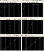
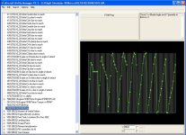
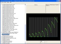
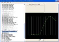
2) Alternatively, we can enter the specified thrust of 1802 flb into the .air file, and proceed to conveniently alter (with AirEd or better with AAM) the following jet engine graphs in a very interesting way, which I actually prefer, as it includes the CV Propeller Thrust inside the engine. One could argue that these graph alterations effectively convert the FS98/CFS1 jet engine into a turboprop:
- Record 601 - Jet Power
- Record 603 - Jet EPR
- Record 604 - Jet N1
Alterations involve making the graph slope on the left, in the lower speed region, a little steeper. This will give us the extra punch needed for accelleration and climbing, without affecting aircraft top speed.
In the enclosed illustration, standard FS98 Jet graphs are shown on the left, and the altered, enhanced graphs, on the right.
Experiments only involving the Power Graph have proven to be insufficient. It seemed that at least the EPR Graph had to be altered as well, but in this case it required an even steeper Power Graph slope on the left, which began to look a bit odd, as it was not so smooth anymore. Thus, best results were obtained with modifications to the N1 graph as well.
I thought this was an interesting and perhaps cleaner way of building a turboprop engine for FS98 and CFS1.
Perhaps this will be of interest to some simmers.
Enjoy!
Cheers,
Aleatorylamp

Attachments
Last edited:


 . I suppose you let us know what will come out of it one day, maybe an F-27 ?


