• There seems to be an uptick in Political comments in recent months. Those of us who are long time members of the site know that Political and Religious content has been banned for years. Nothing has changed. Please leave all political and religious comments out of the forums.

    If you recently joined the forums you were not presented with this restriction in the terms of service. This was due to a conversion error when we went from vBulletin to Xenforo. We have updated our terms of service to reflect these corrections.

    Please note any post refering to a politician will be considered political even if it is intended to be humor. Our experience is these topics have a way of dividing the forums and causing deep resentment among members. It is a poison to the community. We appreciate compliance with the rules.

    The Staff of SOH

  • Server side Maintenance is done. We still have an update to the forum software to run but that one will have to wait for a better time.

Douglas X-3 Stiletto FSX Native

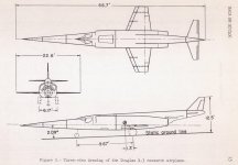
Thanks for the correction and the inclusion of data regarding flaps.. That would have been a hell of a blunder on my part.. It's what I get for pressing calculator buttons way too far past eyelids at half mast in the morning.. I'll be honest. I didnt notice the speed brake in the drawing till after i'd posted it and was looking at uit trying to understand why this patent application only showed le slats and not flaps.. It seemed a bit odd too me. Then i noticed the speed brake and figured at least something good could come out of this as ive never seen a drawing with speed brakes either..

Installed a framework to build this flight model around last night and made some printouts Started looking for engines that could fit in the tiny little spaces they allowed for the engines.. It'll be fun.. Also started pondering ways of making the mean aerodynamic center move backwards during transonic speeds. I think that was the real culprit here as at rest, its already quite far back on the airframe. More study, more learning. I really wish someone was here who could make a pot of coffee. I mean, waking up to no coffee: thats almost inhumane. Its gonna be a long night.. :)
 
Have a look at the attached and guess where the CoG is.
About at the point where the left and right wing leading edges meet at center fuselage, well ahead of 25% MAC.

Did you see the wing planform above and notice the 4.5% thickness?
Also, no wing incidence.
Note the cross section, the flat surfaces between 30% and 75% MAC.
And the LE and TE are exactly center of the thickness.

Pam, I should have a package for you to test within 2 weeks including a basic flyable FM, and proper FSRef, contact points, fuel stations, etc. with all the known data already present. That will make it easier for you to get started.

EDIT: BTW, don't even think about the intended J-46 or Mach 2. I want to focus on the actual use of the J-37 first.

EDIT2: Also note the CoG with wheels up/down in the red/blue highlighted areas.
 

Attachments

  • ms-2018-jan-26-025.jpg
    ms-2018-jan-26-025.jpg
    56.1 KB · Views: 0
  • ms-2018-apr-15-001.jpg
    ms-2018-apr-15-001.jpg
    93 KB · Views: 0
Have a look at the attached and guess where the CoG is.
About at the point where the left and right wing leading edges meet at center fuselage, well ahead of 25% MAC.

Did you see the wing planform above and notice the 4.5% thickness?
Also, no wing incidence.
Note the cross section, the flat surfaces between 30% and 75% MAC.
And the LE and TE are exactly center of the thickness.

Pam, I should have a package for you to test within 2 weeks including a basic flyable FM, and proper FSRef, contact points, fuel stations, etc. with all the known data already present. That will make it easier for you to get started.

EDIT: BTW, don't even think about the intended J-46 or Mach 2. I want to focus on the actual use of the J-37 first.

EDIT2: Also note the CoG with wheels up/down in the red/blue highlighted areas.

Sounds wonderful :)

I did see all of that..
Spent the day today making printouts of test data and applying them to Ito-sama's version just to see what pops, but ive got a long way to go. Ito-sama's dimensions were way off all around. So, i've been making basic corrections there and admittedly taking it up to see how it flies.. One thing i can say is; if there were ever an airplane in need of a nose camera, this is it.. I understand now why they land it on a lake bed instead of a 120 foot wide runway. I'm baffled to think that the sr-71 is landable ::LOL::

I think, the biggest challenge for me will be moving the mean aerodynamic center as the plane passes into transonic speeds. Ariane used to use an include file with its 737's that did a whole lot of things but mostly adjusted the CG depending on the load. I may take a look into that and see if theres a way to make use of at least the methods used to move the MAC back and forth with the speed. However, I'm far from being a coder, so, more to learn.. :)..
I also need to learn how to deal with the main wing trailing edge sweep angle. I've got all the data available for each of the wings stations so there may be a way to make use of that, without cludging in a second sweep angle. NACA was pretty thorough in the observations so that makes it easier in some ways, and admittedly, more confusing in others..

Re: J-34.. Yup.. I intend on getting it right first. Truth told, I've been looking at a bunch of engines this morning that fit that little 24" wide space they made for them, and frankly, only the J-34 fits and supplies enough power to move this thing. The other available modeles, even the brand new ones, all develope power on the 2000-3600 pound area, even with afterburners.. So, for now, the J-34 is the greatest show on earth when it comes to this plane. Later, I'll use it as a basis for building the unbuilt engine that should have been done, but my suspicion is that you just cant pack that much power into such a tiny engine..

Westinghouse_J34.jpg


So the CG is almost four feet behind the Reference datum point ( well, provided my eyes werent too blrry and crossed trying to read my scale ).. This plane just keeps getting more and more aerodynamically interesting by the minute..
 
Sounds wonderful :)

... snipped ...

So the CG is almost four feet behind the Reference datum point ( well, provided my eyes werent too blrry and crossed trying to read my scale ).. This plane just keeps getting more and more aerodynamically interesting by the minute..

I am not sure where the reference datum point is but the CoG is 1.3' in front of the main gear and well in front of 25% MAC. :)
 
I am not sure where the reference datum point is but the CoG is 1.3' in front of the main gear and well in front of 25% MAC. :)

Well, typically, in FSX, the reference datum position is the exact center of the plane: aka where they put the middle of the plane when modelling it. I tnd to place it off the nose though when i'm working on an fde as its easier for me to determine position going backwards than it is to hop arround back and forth from the tail too the nose..

OH.. Yeah. I checked out the CG position you indicated.. The plane flies beautifully..
 
Pam, I put all my models' FSRef and CoG (initially) on the 25% MAC line longitudinally. That keeps me and the aircraft in balance better in my head. :) It's just easier for me to keep locations of weight items in check at a glance when I know the "fulcrum" is 25% MAC. :)

Not a big deal; just my habit.
 
Ive never tried that method. But thats the beauty of what we do. Theres no one right way to do it. If a company provides a specific reference datum point with their drawings thats cool, but, no matter how we do it, we're all working to get too the same place.
 
When dealing with different fuselage lengths for the same wing (think airliners), a 25% MAC reference datum is the way to go as you will only have to adjust any elements forward and aft of the wing instead of anything requiring coordinates.
 
Well, I finished up the modified hexagonal airfoil with its leading / trailing flaps and ailerons, and got all the control surfaces animated, tagged and working. Now on to the gear bays and gear.
 

Attachments

  • ms-2018-apr-16-003.jpg
    ms-2018-apr-16-003.jpg
    12.3 KB · Views: 2
The airfoil is quite interesting in shape, my guess is that it was designed to create two shock waves, one at each break and keep them from moving during mach changes. Split flaps were probably used for structural reasons and to keep a shockwave from developing at the hinge line, which on the XF 92A caused considerable local disturbance and hinge line loading. The wing being only 4 1/2" thick needed all the strength it could muster.

A conventional airfoil has the center of pressure move aft as the transonic area is entered. I wonder where the center of aerodynamic pressure is for this airfoil? I also wonder about the pitch change (possible) with varying power settings due to induced flow under the elevator?

Interesting plane!

I do have a NACA research paper on the wing design, plus two others, Stability and Control Characteristics and Landing Loads.
 
The airfoil is quite interesting in shape, my guess is that it was designed to create two shock waves, one at each break and keep them from moving during mach changes. Split flaps were probably used for structural reasons and to keep a shockwave from developing at the hinge line, which on the XF 92A caused considerable local disturbance and hinge line loading. The wing being only 4 1/2" thick needed all the strength it could muster.

A conventional airfoil has the center of pressure move aft as the transonic area is entered. I wonder where the center of aerodynamic pressure is for this airfoil? I also wonder about the pitch change (possible) with varying power settings due to induced flow under the elevator?

Interesting plane!

The airfoil will behave the same as a conventional airfoil at subsonic speed, just not as efficiently. But it was obviously designed to be optimized for supersonic flow based on it's shape. For reference, see the F-117A, although that was done for LO, not compressible airflow reasons. ;) At supersonic speeds it should have a compression shock off of the leading edge and two expansion shock waves off of the "angle" changes across the airfoil and then another compression shock at the trailing edge where the flow comes back together.

Here's a diamond airfoil reference https://www.quora.com/How-is-Lift-generated-in-Supersonic-Flight

That's an interesting read and comments Sir. Thanks for that.

The X-3 will be a bit more complicated to fly based on this table :)
 

Attachments

  • x3flight ops.jpg
    x3flight ops.jpg
    96.4 KB · Views: 3
Ok, so i'm not finding any wind tunnel data graphs on the web so i'll ask here..

As the pressure cone moves back along the wing, the center of pressure ( Mean Aerodynamic Center ) also moves back??
Since the wing is so far rearward on this plane, if the center of pressure moved far enough back along the wing, wouldnt that create a situation where the leading edge of the wing is providing less lift that the trailing edge??
If the trailing edge is producing all the lift, wouldnt that tend to lift the tail section, causing a downward pitch on the nose??
 
The airfoil is quite interesting in shape, my guess is that it was designed to create two shock waves, one at each break and keep them from moving during mach changes. Split flaps were probably used for structural reasons and to keep a shockwave from developing at the hinge line, which on the XF 92A caused considerable local disturbance and hinge line loading. The wing being only 4 1/2" thick needed all the strength it could muster.

A conventional airfoil has the center of pressure move aft as the transonic area is entered. I wonder where the center of aerodynamic pressure is for this airfoil? I also wonder about the pitch change (possible) with varying power settings due to induced flow under the elevator?

Interesting plane!

I noticed that on the three view i use for measurements, that 75% cord is prominently marked and i have no idea why. According to the research data, the AC/center of pressure is 27% cord at subsonic speed, but travels back through trans-sonicspeeds. Whether the 75% cord is where it ends up or not is something i want to know as well, and i have a buttload of papers on it, but i cant understand a single thing i'm looking at any more.. Perhaps you will have a better grasp of it..

https://ntrs.nasa.gov/archive/nasa/casi.ntrs.nasa.gov/19780022113.pdf

If so, please explain it too me as well.. thanks..
 
Ok, so i'm not finding any wind tunnel data graphs on the web so i'll ask here..

As the pressure cone moves back along the wing, the center of pressure ( Mean Aerodynamic Center ) also moves back??
Since the wing is so far rearward on this plane, if the center of pressure moved far enough back along the wing, wouldnt that create a situation where the leading edge of the wing is providing less lift that the trailing edge??
If the trailing edge is producing all the lift, wouldnt that tend to lift the tail section, causing a downward pitch on the nose??
I expect that'd be a 'yes'.
Perhaps have a look at whatever you can find re compression lift [and cruise] with the XB-70 ..... another a/c that was instrumental in pioneering multi-mach flight design...;)
 
I expect that'd be a 'yes'.
Perhaps have a look at whatever you can find re compression lift [and cruise] with the XB-70 ..... another a/c that was instrumental in pioneering multi-mach flight design...;)


oooooooo. great recommendation.. thank you..
 
Back
Top