Analysing and modifying the AFX file with QBasic.

aleatorylamp

Charter Member
Hello folks,
This would be the continuation of a subject recently started on the "Conspicuous by their Absence" Thread.

Ivan had commented on some small and extremely practical utilities he had written in "C" and using batch files, with which he could make some dreary and long AF99 operations very easy and fast. For example, re-scaling the whole aircraft or moving it to an improved position.

These small programmes involve very simple mathematical actions on aircraft elements present in a given directory, and I was immediately inspired to try and produce similar programmes using QBasic.

I know QBasic is one of the most outdated programming languages, considered by most as only good for Kids, but not even that, because why show them something useless when there´s more modern stuff like "C" and "C++" around...

Well, OK, granted, but I haven´t learnt anything else, and QBasic is the only thing I can understand and use to any effect.

It does have tremendous power to manipulate strings and files though, except perhaps for extracting file names from directories, which I haven´t found the way to do yet. Maybe it isn´t possible.

As a result, I can´t write small QBasic programs that act on all part files stored in one directory, to re-scale or re-position them one after the other, in one go.

However, it could be done acting on the whole AFX. All the vertices are present - they aren´t in the AFA, AFC or AFS files - only the AFP Aircraft Part files show vertices, and so does the AFX.

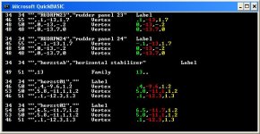
So at the moment, I have got as far as identifying all the lines containing information on vertices present in all the parts corresponding to everything in the AF99 aircraft. ...all except the templates for structures, which is a different matter.

I have also been able to isolate the three x,y,z coordinates for each vector. Now I have to turn them into real numbers, apply some maths to the needed ones, turn them back into text and re-insert them into the string to re-build a new AFX.

The problem with Structures is that they have a different Syntax, so the name of the type of bulkhead template between the first two inverted commas type will serve as identifiers. Maybe I´ll use the firs three letters of the bulkhead names, as the shortest is "Vee". Then, there are only two coordinates for the templates, so I still have to study which is what.

They must also be processed. As the AFX, when unpacked, actually generates all parts, I doubt that un-processed bulkhead vertices will work properly with processed Structure part vertices!

Then there is a mysterious short line with a confusing "", syntax, which however does not correspond to a vertice. It may be the reference number of the Family that the component or Structure is grouped into, as the numbers do not depend on the position and repeat themselves in other models as well.
There are 8 possible numbers: 83, 84 (left-right?), 10 (low wing facing down?), 12 (mid wing facing up?), 26 (canopy?) and 13, 17 (both aft?) and 36 (body?). Ah dunno yet completely, but probably it won´t matter and won´t need processing.

Anyway, here´s a screenshot of my progress so far. The different colours show the vertex numbers. The only ones missing are the Template Structures that have only two coordinates.

Cheers,
Aleatorylamp
 

Attachments

  • Vertex-identify3.jpg
    Vertex-identify3.jpg
    64 KB · Views: 1
Further progress... it´s working!

Hello All,
After managing to identify and isolate the structure templates, came the task of actually modifying certain parameters, and leaving others intact.

To start off, I chose to lengthen a model by a very small amount, and after several different AF99 unpacking errors, creation of garbage structures and components, and other errors caused by missing commas or superfluous inverted commas, or excessive zeroes where there should be nothing, it worked!! My test-model is now a couple of inches longer.

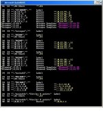
Here is a sample screenshot of a part of the listing that can be can generated so as to check what is going on during the process. The culprits were the short lines (labelled by me as "Short", for me to monitor) that have a certain value, one of 12 possible numbers I believe, and which is repeated in other models, and must not be processed.

My deduction is that is depends on the family group of a mainly a component or structure, and its orientation. However, there are also other short lines that can be upto 2 positions longer, and they can´t be processed either.

Now, the next part is to either rip out the wheels before processing, because they shouldn´t be stretched. Alternatively, they could be identified and be ignored (which would be more artfull) by the stretching process, to be shifted manually from within AF99 perhaps.

Following that, texture mapping can also be identified and corrected to fit the stretching...

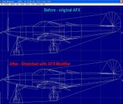
P.S. From the second screenshot one can see that the "victim" is the original AiraCobra AFX by Eric Johnson. It was useful to use that as a reference point for my experiments, as Ivan had also done some research with effective "C" programs to facilitate quick adjustments on the entire model, that would otherwise take ages to perform manually with AF99.

Interestingly enough, no offsets of any kind needed processing - neither the CoG offset, which this model has, nor e.g. the Wheels, that are originally built at the origin (0,0,0) and shifted into position on the Assembly blueprint.

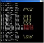
As regards the first screenshot, the coloured lines at the end of each line is the modified output of the modified lines. The original lines are the white ones on the left, and do not include the first two numbers - those are reference character codes of certain positions that are of assistance to check the parsing. Once proven correct, they could of course be deleted, as I did for the Structure Template identification to make space.

Update: Greater precision with 2 decimals.
At first I thought it wouldn´t handle 2 decimals in the vertex coordinates, as the model only has upto 1 decimal after the point, but then I remembered a comment in a recent post on the Conspicuous thread about AF99 handling upto 0.01 ft precision, and it worked fine, so here´s an update of the results screen section screenshot, substituting the old one.

Cheers,
Aleatorylamp
 

Attachments

  • AFX compared.jpg
    AFX compared.jpg
    92.5 KB · Views: 0
  • Two-decimals.jpg
    Two-decimals.jpg
    79.6 KB · Views: 0
Last edited:
Hello all,
I just missed something: Wheels and Propdisc haven´t budged! - because...
La-dee-dah!, they were built at origin, 0,0,0. Oh, what fun! They were offset.:nightmare:

I was completely wrong about " no offsets of any kind needed processing etc..."
...famous last words before blundering.

Now I´ll have to make the programme identify them for moving slightly,
...or apply the maths to the offset points. Let´s see...
...or put in the parts into their proper position with AF99 let´s see if they´ll allow
themselves to be moved, because often they slip back) before running them

through the modifier.

Ideally a program like this should detect null-point-built elements and
intelligently place them, but that´s a bit difficult to program.
Cheers,
Aleatorylamp
 
Last edited:
Hello Aleatorylamp,

I don't happen to know what scaling factor you are using but there is a reason why I chose some really large (2X and 3X) scaling factors for experimentation.
With small scaling factors, something can still be wrong and you will never see it.
As an example, you only saw the Wheels and Prop Disk.

This screenshot that I originally attached back at Post 1493 in the "Conspicuous by Their Absence" thread will give you an idea of what else is a bit mis-located that you are not seeing at the moment.

As we have discussed offline, it does not work to actually move the AF99 Part because often a single Part will appear in multiple pieces and MOVING the Part will move them all which may cause effects that are very hard to work with.
Our goals may have been different, but mine was to create a program which does as much of the alteration in an automated fashion as possible without any major detail work on the pieces.
I actually did not quite do that.
The StretchIt program worked on Parts.
Components are thus affected without any need for separate consideration.
Structures, however, were not addressed at all.
I found it simpler to re-build the Structures individually because on this project, I had intended to alter the Bulkheads (cross-sections) of most of them anyway.
A Triangular Cannon Barrel just does not look right when there are so many resources left over.

I am glad you figured out that the single decimal place in the original model could not be retained with the kind of editing we are doing. The ability to put together a fairly good looking model with such low precision is why I believe Eric Johnson did a really great job here. There are places he could have done much better, but many of the improvements we are doing here are possible because the tools are better.

- Ivan.
 

Attachments

  • NotWellAdjusted.jpg
    NotWellAdjusted.jpg
    41.5 KB · Views: 1
Hello Ivan,
OK, thanks!
With the small fuselage-length correction, I suppose the numbers of other discrepancies are too small. I was using the same 1.0191 multiplier as you had done that excluded the nose-cannon from the specified length of the plane. The screenshots have the grid on to show the difference, although it is not calibrated.

Incidentally, I didn´t process any of the offsets. I haven´t posted a screenshot of the model yet because the textures aren mapped correctly yet.


Parts created at the null point won´t react to ANY scaling and stay put, and one can only really act on them through the offsets, or on the AF99 model itself.

Here, the problem is that the parts not only have to be placed correctly, but have to be shifted back, and it sometimes doesn´t really work as expected, now I realize that it´s for the reasons that you have just explained, so it´s better to delete the old ones from the list of the original model and put in new ones. Then, the AFX modifier will work fine - I hope! I´m just doing that now, and I´l take advantage of the situation and put in some 12-sided wheels.

The screenshot looks like the plane has taken some severe hits - flak maybe... Things are disjointed and missing - the wheels have been shot off and are already distant!

Anyway, I agree with your comments on the original E.J. AFX - it´s quite nice to work on!

Cheers,
Aleatorylamp
 
Hello Ivan, Hello all!
It´s done! It´s doing what was aiming for, namely adjusting the model´s dimensions to apply
overall corrections after having started building. This will save a lot of work and time.

As I never build with offsets, I don´t have to include corrections for shifted parts, and I do texture mapping from within AF99, so that won´t need to go into the program either.

Here´s a partial screenshot showing the old vertex coordinates in white, and the modified ones in yellow, and red for a structure template.

Cheers,
Aleatorylamp
 

Attachments

  • Image2.jpg
    Image2.jpg
    99.1 KB · Views: 1
Hello Aleatorylamp,

I am glad you accomplished what you had set out to do.
I don't believe this kind of tool would have ever been useful for any of my own projects.
When I screw things up, I screw them up MUCH worse than a uniform 2% scaling factor which is why I had not done a program like this until I began to examine this P-39D AFX.

- Ivan.
 
Future plans for the test bed.

Hello Ivan,
Mini-tools like yours would have been obviously been easier to use, but I can´t make them for reasons I´ve explained. The only thing I can accomplish is to act on the AFX file with QBasic, which incidentally, I thought was pretty interesting, albeit rather peculiar.

What I will also do with it (and describe it on this thread), once it comes to the point, is generate a separate AFX for the fin, scale that with my program, unpack it and put the pieces on the P39D - test-baby conveyor belt. It is the way I can use my AFX Modifier to act only on selected areas of the plane, so it will be useful for that too! ...at least for me...

Now, because I don´t like leaving pets stranded, abandoned on a country road, I won´t abandon my results on my modified E.J. AFX. They will continue serving me, and I will make good use of the test model, just for some practise as I explained when you so kindly sent me the AFX, thanks to which my Apprentice Department is having a great time!

I observe that the wheel and exhaust textures share half of the same texture-bitmap each, and re-scaling has (naturally) made rather a mess of the mapping. AF99 will do a good job of re-mapping textures except for the wheels and exhaust ones, that will have to be entered manually.

I can see the numbers on the original texture-spread, so maybe that will serve as a guide for me to understand how that has to go, once I elongate the nose-gear by 0.50 ft, thanks to info as per your investigations on the other thread! Also, I´ll clean up the bits and pieces on all gear struts.

Then, I shall proceed with a 179 alpha transparency canopy structure (speed below 179 for AA), to see if anything worth commenting upon happens, put in an inhabitant and do a nice glue-sequence for the cockpit.

And, to finish, there is a planned conversion of the octogonal cross-sectioned fuselage components to be dodecagonical, (taking advantage of the situation to make the belly a bit more pot-bellied), and give the tail-plane an airfoil section. Then, if nothing else crops up, at the end, my apprentices will be able to fly about in their own updated Airacobra, and practise their engineering skills on the engine too!

It will probably continue being fun!
Cheers,
Aleatorylamp
 
Hello Aleatorylamp,

Aleatorylamp said:
Mini-tools like yours would have been obviously been easier to use, but I can´t make them for reasons I´ve explained. The only thing I can accomplish is to act on the AFX file with QBasic, which incidentally, I thought was pretty interesting, albeit rather peculiar.

I never really did understand the logic of not being able to work with a simple process but preferring to deal with a much more complicated process. It just does not make any sense.

Aleatorylamp said:
What I will also do with it (and describe it on this thread), once it comes to the point, is generate a separate AFX for the fin, scale that with my program, unpack it and put the pieces on the P39D - test-baby conveyor belt. It is the way I can use my AFX Modifier to act only on selected areas of the plane, so it will be useful for that too! ...at least for me...

Your description of packing just the Fin into a new AFX file in order to do some fairly simple processing seems like a rather convoluted way of accomplishing a very simple task.

This proposal actually brings up a LOT of other questions:
1. Where did you get the idea that the Fin is out of scale in relation to the rest of the 3D Model?
2. Which way are you planning on stretching / scaling the Fin Parts?
3. WHY are you bothering to do anything at all with the existing Fin Parts when they also have the Diamond cross section instead of a proper Airfoil shape?
If you are going to do some heavy editing to those pieces, why not just build them from scratch. It would be quicker and simpler.

Aleatorylamp said:
Then, I shall proceed with a 179 alpha transparency canopy structure (speed below 179 for AA), to see if anything worth commenting upon happens, put in an inhabitant and do a nice glue-sequence for the cockpit.

And, to finish, there is a planned conversion of the octogonal cross-sectioned fuselage components to be dodecagonical, (taking advantage of the situation to make the belly a bit more pot-bellied), and give the tail-plane an airfoil section. Then, if nothing else crops up, at the end, my apprentices will be able to fly about in their own updated Airacobra, and practise their engineering skills on the engine too!


it seems to me that you are going about this in the wrong order.
When you start looking at how to put in a Transparent Canopy, Cockpit and other cool things you will see how the current divisions of the Fuselage won't work well with that idea.
It makes a lot more sense if you are going to spend the time to build a 12 sided Fuselage to do that first and plan for the Cockpit and Transparent Canopy ahead of time.
You will avoid a lot of problems that way.
You will also find out what is really wrong with that Aeroplane's Tail; It really isn't a scaling issue.

I chose not to go there because I saw that when allowing for the precision possible with Aircraft Factory 99, just about EVERYTHING in this model had a shape problem so it didn't make sense to do more than just correct the most obvious problems that were the most benefit at the least cost in time.
I had to go further than I wanted because as I pulled on one string, others would unravel and I could not leave the patient bleeding from other areas even if I had not been working there.

- Ivan.
 
Hello Ivan,
Thanks for your message.

I don´t believe you understand my position very well when you say
>"I never really did understand the logic of not being able to work with a simple process but preferring to deal with a much more complicated process. It just does not make any sense."<

It is of course very simple for someone who is used to programming very well in C and in MS-DOS, but as I´ve already said, it is MUCH easier and more understadable for me to do it with a programming language that I know, and that I know can do the job for me. I´d have to learn C and MS-DOS, before being able to do the job so simply, and it would be more difficult and take longer than using QBasic now.

When I mentioned the fin, it had to do with your comment in Post#1527, where you said the rudder/fin was too high, but possibly you didn´t mean what I thought you meant!

Now that I have looked a bit more closely at the two diagrams you posted in your posts #1484 and #1482, comparing Paul Matt´s drawings to both the stretched and unstretched models, it is obvious that the fin is too high, but not because of the fin itself - it is the fuselage-tail that goes up to high, and the fin is sitting on it.

So, correcting rear the fuselage angle to go down a bit, will provide a new correct height for the existing fin to sit on, whether in its diamond cross-section or as an airfoil. The fin then won´t have to be re-scaled, just moved down.

I could do it by shifting the component down in a skiving way, or re-position it as an AFX with my Qbasic program, or re-building it with a correct cross-section from scratch, the latter of which, as you say, I agree would be the most logical.

And, as the rear fuselage would have to be re-built, the whole fuselage would be done in 12 sides while I´m at it. As a re-building exercise, the model is quite a challenge.

How about writing a program that converts 8 sided bodies into 12 sided ones? Just joking...

I mentioned the transparent canopy as being done before the intense fuselage re-build, because it is an easy way of enhancing the model. Built as a top-only transparent structure thanks to AA, it would be a piece of cake to fit to a possibly later re-worked fuselage, if that were to be built. Fitting a couple of frame pieces won´t pose a problem either.

Depending on the complication involved, I may do the lot, or not... I´ll see how it goes.

Cheers,
Stephan
 
Hello Aleatorylamp,

I think we are mostly in agreement about how the Fin needs fixed and why I stated that the Fuselage needed fixed first.

Regarding Simple and Complicated programs:
I was not suggesting that you learn C programming to work with these Parts editor programs.
It was more a suggestion of building programs with a command line interface using whatever language you are comfortable with and working on a single Part at a time.
Properly done, the single Part program could be called by other programs to handle Components via "Sysem" calls in BASIC.

As an example:
MoveIt - Moves ONE Part.
CMoveIt - Calls MoveIt on all the Parts of a Component
StructMoveIt - Pretty Obvious purpose.

Mirror - Reflects One Part across the Y-Z plane to get a New Part
CMirror - Builds a Mirrored Component. Conceptually the same, but does not call the "Mirror" program....

I just found it odd that you would write the AFX modification program without the smaller programs first.

Does your AFX program also do a Move? I had thought it was only doing a Stretch?

Regarding Flight Models, I am still doing data collection for my version.

- Ivan.
 
Hello Ivan,
I haven´t needed a Move program yet - I was actually waiting, for example, for a better place to set the CoG, to practise a possible MoveIt version that would globally affect the whole airplane.

With a 0.5 ft lower nose gear, For the moment, the present positioning of the CoG is so critical that the aircraft often sits on its tail, only with the adjustment the lower nose gear, and would require the main gear to be set back by at least 6 inches in the .air file.

Doing a Move would be a second version of the same program, containing an adder instead of a multiplier. The moving factor, like the stretching factor, would be entered into the program text first. That way I can avoid having to create an interface with a selection menu.

At the moment, the Stretching program applies the same multiplier to the 3 coordinates in each vertex line, taking for granted that a uniform stretch in all directions is desired. Alternatively, three different factor variables could be written in, so that some could be left at 1:1 if desired.

I understand what you mean with the program concept you describe, but there is a problem.
To call subroutines that select a part or parts from a directory for processing, would involve entering the names of the parts into the program, but the point is that this is better done automatically.

I can´t just have one part in a directory, for example, and expect the program to identify it and to process it, unless I give it the name of the part.

Doing a Dir of the directory shows the names on the screen, but there seems to be no way to have the computer store the filenames so files can be accessed automatically by a program. The only thing to do would be for the user to select a part having done a Dir, and then enter its name so that the computer can choose it. It seems a bit cumbersome, and it would be easier to do it directly in AF99.

That was the reason why I had to use the AFX, as it acts on all the parts in it, and also the reason for making possible partial AFX´s.

Cheers, and good night!
Aleatorylamp
 
Hello Aleatorylamp,

Aleatorylamp said:
I haven´t needed a Move program yet - I was actually waiting, for example, for a better place to set the CoG, to practise a possible MoveIt version that would globally affect the whole airplane.

Actually you have needed it. I think it was on your AT-9 Jeep.
I did the move of the entire Aeroplane for you if I am recalling that project correctly.

Aleatorylamp said:
With a 0.5 ft lower nose gear, For the moment, the present positioning of the CoG is so critical that the aircraft often sits on its tail, only with the adjustment the lower nose gear, and would require the main gear to be set back by at least 6 inches in the .air file.


Out of curiosity, whose AIR file are you using to make this determination?
I can tell you with great certainty that your conclusion here is not correct: at least not entirely correct.
There are a few more factors involved in determining how the aeroplane sits.
I have most of the items located fairly accurately now but I am using P-39Q Data which is a bit different from the early P-39D. It is close enough to come to a few conclusions though.
At the moment, that particular Spreadsheet only contains P-39Q Data and I have not tried to adjust for differences for the P-39D, but I do not expect any great surprises when and if I do that.

The screenshot of the Airacobra sitting on its tail I posted was, as I should have noted, extremely difficult to get.
I have not been able to reproduce it the last 30 or so times I have tried.
.......
I was just about to tell you what I was actually doing on my Airacobra Project but that would be seriously hijacking your thread.

If you want a listing of the AF99 Parts files, enter this command:
DIR /b *.AFP > AfpFileList.txt

As I mentioned earlier, this command will give you a "Bare" listing with jut the File Names and nothing else.
I also sometimes create a dummy Component usually called X1.AFC containing a bunch of Parts I want to move.
When I run CMoveIt on that Component, it moves all the Parts at one time.
This idea would also work if you want to create a list of Parts with nothing else.
Create the AF99 Component and then edit the AFC file to delete the Header and other useless sections.

I tend to use partial AFA files, but have never tried to do a partial AFX file.

- Ivan.
 
2 in 1

Hello Ivan,
I do remember your moving the entire AT-9 Jeep forward to solve a cabin bulkhead bleed problem caused by an inconvenient CoG position. I meant I hadn´t needed it for the Airacobra yet.

In the case of the P-39D cockpit bleeds aren´t so much the reason, because I haven´t got round to doing the transparent cabin yet. It is more a case of applying the possible results of your CoG study affecting the visual aspect of flight behaviour.

BTW: No hurry, I can wait... and it´s not vital if it´s inconclusive, so not to worry!


You had also commented that the landing gear position on the model you had was quite critical. The model I have, is made from E.J.´s original AFX, apparently, and put into one of 14 packages by one Deke Wakefield, with FS98 FD by Christoph Ruhtenberg. The .air file is named P-39C.air although the model is named P-39D.

Main-gear FD contact points in the FD are: l/r 71, u/d -61, f/a -14. As soon as I´d built the 0.5 ft longer nose gear and lowered the nose contact point by 0.5 ft, while I was adjusting the fuselage angle to prevent the jerk-bounce upon loading the aircraft into FS, the aircraft easily sat on its tail, so for the meantime, I merely moved the landing gear position backwards by -6 inches.

A question: What language does the instruction DIR /b *.AFP > AfpFileList.txt belong to?
In QBasic, as I´d commented earlier, all the instruction FILES "*.afx" : PRINT does, is output all the .afx files onto the screen, and there seems to be no provision for anything like placing filenames into a variable or dimensioned variable for use from within a program.

That´s why I have to do everything to an AFX file, that will contain all the parts required for a modification, without being in a directory I can´t access the files from.

The only reason I didn´t name this thread with anything related to the AiraCobra´s names, was so as not to step on your toes, as the P-39 is really your project.

I only want to test some things using the original E.J. P-39 AFX to a) see how successful I can be with QBasic AFX modifications, and b) to do some AF99 aircraft updating on it, to give that activity another try after being put off some time ago.

The Test Bed is the Airacobra, definitely, so please feel free to make any comments on your own P39 improvements that you wish! I AM very much interested, if you are willing to give your opinions on the subject - I´d very much welcome that on this thread, and wouldn´t say it would be hijacking, quite the contrary!

Incidentally, I got the nose-wheel texture centered by adjusting the numbers in the AF99 texture spread window, and by the way, the flaps are not split flaps under the trailing edge, but cut out of the wing trailing edge.

OK, then. The cats are jumping on my keyboard again!

Update: Cats are fed...
I just put in a mode selector into the AFX Modifier, which either reads "Stretch" or "Move", depending on whether the x,y,z modifiyng factors will be multiplied or added. For the moment, all this is written directly into the program code, which seems easier than having to input the mode and the 3 factors into a line every time you run the program.

Incidentally, I found 3 other shifted elements: The prop blades!! I´ll fix that in AF99 of course.
You can see them on the shrunk airplane screenshot.
The other one shows the airplane moved forward and upward. (Note how the red vertical and green horizontal centre-lines have been displaced.)

Uptate:
Another thing you mentioned a while back, that I can see now on the AFX, is that it is interesting to see how other people build (or built) things. Looking at the nose gear yoke, as well as the triangles on the main gear struts, this building style seemingly corresponds to 3dfx graphic card capacity of the time. Modern 3d graphic cards now use OpenGL which apparently cannot display that style properly, because of their more sophisticated texture-shading system, even though basically both use "hardware accelleration".

Cheers,

Aleatorylamp
 

Attachments

  • Cobra-move.jpg
    Cobra-move.jpg
    48.1 KB · Views: 0
  • Cobra--shrunk.jpg
    Cobra--shrunk.jpg
    34.6 KB · Views: 0
Last edited:
Hello Aleatorylamp,

Let's take care of the easy stuff first:
The "DIR" command is what you would type if you open a MS DOS / Command Prompt window.
I can tell you it still works with "Command Prompt" as late as Windows 8.1 which is what I am running on this Laptop.

Aleatorylamp said:
Incidentally, I got the nose-wheel texture centered by adjusting the numbers in the AF99 texture spread window, and by the way, the flaps are not split flaps under the trailing edge, but cut out of the wing trailing edge.


When you moved the Nose Wheel, It would have been a good idea to create a Reference Part for where it USED TO be.
That way, you know the exact offsets to change the Texture Mapping in AF99. This is the reason I keep a hand held (as opposed to computer) Calculator by my Development Computer. It is nothing special. I think the current one is a Ti-30 or Ti-35, but it helps with the math without having to find the Windows Calculator.
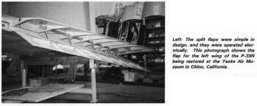
The Airacobra had SPLIT FLAPS..... See the attached image. It was lifted from the "Detail & Scale" book.
I have a copy on my shelf, but generally use the PDF copy I found online even though it is much inferior to the printed copy.
Just do an Internet search for "P-39 Airacobra Flaps" and you will find a LOT of images. Most of them will be model aeroplanes, but these guys are much more serious rivet counters than I am.
For a good 3D model, I suggest you fix the Flaps to be Split Flaps like they were on the real aeroplane.

Regarding the P-39C:
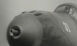
You need to decide which variant of the P-39 you are attempting to build. It is important because a lot of things depend upon that decision. The P-39C had all of its Guns in the Nose which means its CoG will be a bit different and also weighed a LOT less than the P-39D and later because it had no Armour or Self Sealing Fuel Tanks.
See attached image for P-39C Armament.

Thanks for the consideration about the P-39 being "My" Project.
I actually didn't think you had an interest in this aeroplane at all.
I guess I really should start a thread on "My Build" even though I actually can't build anything at the moment.

I am very hesitant to post my conclusions thus far because I really don't like the idea of posting something when not all the data has been worked out and then having to revise it later. Sometimes this happens because of an honest mistake or because of new information, but in this case I KNOW I haven't used all the information currently available to me.

I didn't know you were waiting on me to provide Center of Gravity data. I was kind of hoping that you would do your own calculations and see if we arrived at the same conclusions.
In any case, here is some information that should help you correct your AIR file so it doesn't sit on its butt so often.
I believe my version is pretty close at this point and it is near impossible to get it to sit on its butt.

These are with current data and subject to change as I refine calculations.
The Stretched Model actually ended up VERY near correct for Longitudinal Center of Gravity as compared to my estimates.
If I were you, I would leave that number alone for now.
The VERTICAL Center of Gravity is quite a bit off though.
It should be around 8-9 inches (I think I used 9 inches) below the Thrust Line.
I believe the current MDL has it at about 13 inches which won't totally ruin things either, but it help to get things closer to get the Landing Gear positions correct.

The Main Gear should be +- 68 inches Left - Right according to Paul Matt's drawing and according to the manuals.
The contact point should be 18 inches aft of the CoG.

Ready for this one????
I believe the BIG Balance Killer on this flight model is that the Fuel Tanks are incorrectly located by A LOT.
I don't happen to have even my Game Computer operational at the moment to check all the numbers, but I believe the Fuel Tanks should be a couple inches below the CoG and aligned with the CoG Longitudinally.
They may be actually an inch or two AHEAD of the CoG in reality, but this is where my current calculations have not quite pinned things down yet.

This sounds pretty stupid to not know where the Fuel Tanks are. I sort of do, but only for the later P-39Q which doesn't carry the same fuel load. The problem is more that I don't know for certain where the CoG is in relation to the Fuel Tanks but I don't think this amount of shifting will noticeably affect your flight model or mine for that matter.

If you feel like it, email me your P-39D and I will take a look at it when I can. As I mentioned earlier, my Game Machine is not operational at the moment; It's monitor is being used to test other machines which are a higher priority. Don't bother sending me the AFX. I have no means of examining it.

- Ivan.


Attachments

  • P-39_SplitFlaps.jpg
    P-39_SplitFlaps.jpg
    61.2 KB · Views: 0
  • P-39C_GunsCropped.jpg
    P-39C_GunsCropped.jpg
    21.8 KB · Views: 0
Hello Aleatorylamp,

Aleatorylamp said:

Uptate:
Another thing you mentioned a while back, that I can see now on the AFX, is that it is interesting to see how other people build (or built) things. Looking at the nose gear yoke, as well as the triangles on the main gear struts, this building style seemingly corresponds to 3dfx graphic card capacity of the time. Modern 3d graphic cards now use OpenGL which apparently cannot display that style properly, because of their more sophisticated texture-shading system, even though basically both use "hardware accelleration".


I almost forgot to point out:
I actually AM running 3dfx Graphics Cards. 3dfx (I think they were eaten by Nvidia long ago) was the maker of the Voodoo series of Graphics Cards and my old Development Machine had a Voodoo 3 3000 and my Game Machine still has a Voodoo 3 2000. My own opinion is that the 3dfx Graphics Cards were very good for the time (which is why I bought two) and even today are pretty well thought of. I also have their competition of the time, the Nvidia TNT2 M64 but have only used it for testing. It wasn't until I recently that I found out what this Nvidia PCI test graphics adapter really was.

- Ivan.
 
Hello Ivan -
A quick reply to the latest, like the stack in a computer: Last in, first out.

I loved the 3dfx cards, because they I think did a much better job and seemed
to be programmed more eficiently than OpenGl, even nowadays, if the O.S. or
the hardware can cope.

The OpenGl graphics card on my tower now, can´t handle hardware accelleration
in FS98. Were I to remove it and only use the 512 Mb graphics capacity embedded
in the CPU (called APU), then FS98 h.a. would work!!
FS98 uses, as you know, 3dfx only. But then, I´d have a super graphics card sitting
on the shelf...

I had a friend who swore by the NVidia TNT and TNT2 like the Matrox Millenium. I was
using one on an old computer, and you couldn´t do better!

I think that´s why some aircraft visual model glitches are not visible on old graphics cards,
only becoming visible with hardware accelleration turned off.

Allow me to respond a bit later to the items in your other message,
i.e. the next one in the proverbial stack!

Cheers,
Aleatorylamp.
 
Hello Ivan,
I´ve just been fiddling with the propeller´s new blades as a component, a split spinner with glue between the slices, and a prop blurr. Then I´ll deal with a more convenient nose gear. It´s coming out in a rather clean way, luckily. Not a bad model to work on at all!

Now then, here´s the reply to your comments two posts ago, as promised:

OK on the Dir command! I know the MSDOS Command window works also in Windows XP, but what to do with the bare listing obtained after entering this Dir command is another matter. I´m afraid I´m quite out of my depth.

When I lengthened the nose gear and lowered the nose wheel on the stretched model, the unstretched one still existed elsewhere, and served as reference to get the old texture mapping numbers. I moved what I supposed would be the imaginary texture square forward until the texture was centred on the wheel, and then it required very slight vertical adjustment.

Until yesterday, I hadn´t noticed the flaps issue, as I thought they´d be OK, which they aren´t.
I know they should be split flaps and the E.J. AFX has cut-out flaps. That will expectedly not be a difficult fix. Curiously this model has the wing divided into upwards and downward facing components!

Regarding the P-39C variant:
I had already decided on the P-39D, as the P-39C was not really well prepared for heavy combat. I believe the FS98 .air file already accounts for it, and there are also guns on the wings in the Dp files that came with the FS98/CFS1 model.

At first, I wasn´t really interested in the plane, but my interest was spurred on as I was following your P-39D improvements on the other thread. I was surprised that when the Stance was corrected, the model started getting a character it didn´t have before. It got a totally different look, and I began to like it. It will get even better when the tail-fuselage business is corrected.

Working on the model, I get the same feeling as you did: I is a good model to try out different things. The real plane has beautiful lines, and the model starts looking better and better as you go along, which is an important motivating factor.

I understand your views about the CoG research results. That´s why I was trying not to hurry them, and was patiently satisfied with my provisional fix.

My own calculations were more like a rule of thumb issue. I noticed that the AFX had the light blue spot in a position that looked quite fine, I thought, about 25% from the leading edge along the wing chord, so I was happy to leave it that way.

I posted the pictures of my stretched and unstretched models with the CoG Point, and also the numbers, so that you could have a reference to go by as your development machine wasn´t in running order.

Thanks for the interesting confirmation that the longitudinal position is as I thought! Your stretched model would be the same as mine, so that´s fine.

Now, if the vertical CoG is quite a bit off and should be about 9 inches below the thrust line, it has to be adjusted - either in the AF99 CoG positioning menu option, or with MoveIt (or the Move option in my program). I believe both ways will have the same result, and both will then get readjusted in the .air file.


...and OK on the Big one! The fuel tanks. I´ll try what you suggest provisionally, about 2 inches ahear of the CoG, (and also check the munition weight and position in the Dp files). Firing the rounds and using up fuel should be perhaps be only a little noticeable in the flying behaviour!

Don´t worry about the .air file on my machine for the moment. I find it flies quite nicely - Christoph Ruhtenberg did very nicely here for FS98.

But, as a good CFS1 .air file is planned here, I don´t think it´s worthwhile putting too much effort into a FS98 .air file. Thanks for the offer anyway!


Cheers,
Aleatorylamp
 
Hello Aleatorylamp,

Here comes the Can of Worms:
First Worm:
When you rebuilt the Spinner into two Structures, did you correct the incorrect shape or the diameter which is way too small and I believe the Spinner is also too short?
Problem is that if you correct that without correcting the Nose, there is a mismatch.....
That is why I only replaced the Propeller Blades and didn't worry about the bleeds there.

Second Worm:
The Propeller is the wrong diameter and obviously the wrong shape..... but you probably already knew that.
My rebuild wasn't that correct either, but I intend to do better on the real model.

I had thought EJ's AFX had Split Flaps, but perhaps I fixed that years back when I first got the AFX.

Aleatorylamp said:
My own calculations were more like a rule of thumb issue. I noticed that the AFX had the light blue spot in a position that looked quite fine, I thought, about 25% from the leading edge along the wing chord, so I was happy to leave it that way.

I posted the pictures of my stretched and unstretched models with the CoG Point, and also the numbers, so that you could have a reference to go by as your development machine wasn´t in running order.


I don't really know what it should look like on EJ's P-39D because of distortions and for that matter, I don't even know what it should look like on ANY profile.... I just know that my calculations with a minor estimated correction for model variations put the CoG at about 31-32% of Mean Aerodynamic Chord. Not quite sure what that corresponds to on the model. It is buried in the Spreadsheet calculations somewhere.
25% MAC would be a good estimate for an Aeroplane that is well behaved, but we know that the Airacobra was not so well behaved which is why we can't just estimate. If we go by estimates, it ends up to be pretty average and loses its character.

Aleatorylamp said:
...and OK on the Big one! The fuel tanks. I´ll try what you suggest provisionally, about 2 inches ahear of the CoG, (and also check the munition weight and position in the Dp files). Firing the rounds and using up fuel should be perhaps be only a little noticeable in the flying behaviour!

Don´t worry about the .air file on my machine for the moment. I find it flies quite nicely - Christoph Ruhtenberg did very nicely here for FS98.
The DP file that comes with the CFS version is pretty much garbage.
There is nearly nothing useful in that DP file.

Firing off the ammunition actually had a rather serious effect on the handling of the aeroplane.
My earlier calculations showed that expending the Fuel also had a slight effect but data from the P-39Q suggests that it should not.... There is more to this story though.

Thank you for the vote of confidence on the good CFS AIR file. We shall see where it ends up.

- Ivan.
 
Mysteries return... but get solved too

Hello Ivan,
OK on the flaps, and I noticed the spinner thing, thanks!
I didn´t change the shape either, other than splitting it for the prop component and the glue. The fuselage would need re-shaping first, and I probably won´t do that after all, because of the worms that come out in this work. The "workms"!

So, I finished re-vamping the nose with only a new 12-sided spinner, props with better shapes and uniform lengths and positions, and the lengthened nose-gear.
This, as a preliminary face-lift, with a nice prop-blur included! Classified as a nose-job!!

I wasn´t too worried about the small bleeds - yet - because I was more interested in the CoG shift to the newer position (thanks very much for your suggested new CoG position!): A bit further back and a bit further down - fine to do with AF99, but I wanted to get the whole model to sit on that new place with its null point!

Sounds coherent, what you say: The centre of rotation being where the CoG is, and the centre of lift, infront a bit (offset in the .air file), would then cause the inherent instability that this aircraft had in certain circumstances.


So, I deleted the AF99 CoG offset 3.5,-1.1,0 to make it 0,0,0, with the intention of correcting the re-vamped P-39D with my AFX Modifier Move Option.


But... Oh, Woe! NOTHING except the spinner templates (the vertical one didn´t even exist because I used "Longitudinal Symmetry") were visible in the new, unpacked Model!! And this with no error messages of any kind!

Backtracking, it turned out it was not the CoG shift itaself that was creating the problem, but something in the "nose-job", combined with it, because both the original AFX, and the stretched AFX, do allow Moving the aircraft to center its null point on the new CoG position.

Update
: I discovered is was a new short line that should only be like "",-2.41 right at the beginning of the AFX listing that mistakenly had extra commas and parameters, so it has to be parsed the same as other short lines like "",83 , which are identified but must go into the newly generated AFX unchanged. Allowing three more characters in the cropping of these short lines cured the new problem.

So, the re-positioning works, and so does the "nose job", which is a relief!

However, all this won´t eliminate further worms. After a face lift that probably will not involve a new fuselage any longer, or anything else that´s difficult, I think my I´ll finish my re-working exercise - it´s only for practise anyway, and the resulting aircraft will have served its purpose - and also look a bit better!

Extra Update:
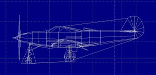
OK! So here are two screenshots with the 0,0,0, at the centre of rotation.
It´s now 18 in. below the centreline (prop axel), and I was trying for about 30% from the leading edge, but I think I fell short and it´s only 27 or something, and will probably have to to go a bit further back. The question is whether this concept is correct, to have the null point on the Centre of Rotation.


Then, I still have to re-map all the textures, as it has all changes, of course, but that should be no problem: Easy skiving with AF99-automatization!

I gave up on sharing one bitmap with different areas for wheel-doors, exhaust and wheels, because I was going crazy, and my psychiatrist is on an extended holiday because he is deranged completely himself, so now there´s an own bitmap for each of those.

Cheers,
Aleatorylamp
 
Last edited:
Back
Top