Conspicuous by Their Absence

Dp files memory hungry?

Hi Smilo,
Thanks for your efforts and your discoveries! Arrogant know all, no way, by the way...!
I think the Dp files eat up a little more memory, because the last time CFS1 shut down with the panel, Windows XP complained that it had insufficient memory - XP only recognizes 3 of the 4Gb I have installed anyway, and then on top of that, grabs 512Mb more for the graphics card, even though that thas its own! It´s a well known XP flaw.
Will CFS1 run on Win7? I know FS98 won´t, and even on XP with a fast graphics card, FS98 flickers terribly with hardware accelleration. But then, CFS1 is superior, so maybe it would work. But then, I know AF99 won´t...
Cheers,
Aleatorylamp
 
idling the old aero-engines in the .air file

Hi all again:
Further to controlling engine idle in the Throttle Effectivity Table in the .air file:

I had forgotten to mention that I´d raised the first Y parameter from 0.2 to 0.98, having raised the second one from 0.98 to 1.2, as I said before. I hadn´t mentioned that idle RPM was just above 600 RPM.

I had the feeling that the engine had slightly more power at full speed - just under 1 knot. I presume this was due to the higher second Y parameter, as this table also affects "max MP wrt intake" (what does that mean?), not only throttle idle stop.

So, I put the 2nd Y parameter back down to 0.98 where it was originally, and the engine still idled fine. Then I decided to see how far down I could get the first Y parameter before it would fail again, finding that at 78 started well a couple of times, failing once, idling at just under 500 RPM. I think I´ll leave it at 80.

Cheers,
Aleatorylamp
 
Throttle Effectivity Table

I have also seen this called Volumetric Efficiency which I believe is a better description.
After all, Why else would a maximum value be only 0.98?
It kinda reminds me of setting the Minimum Airflow by the throttle limiting screw on a car engine tho that was on a computer controlled enginre.

Typing on an iPad is a pain!


- Ivan.
 
Throttle effectivity table

Hi Ivan,

Interesting... If this were 1.00 instead of 0.98 I suppose it would mean perfect efficiency, i.e. utopia.

I started browsing around and found it´s also called "WOT flow restriction" - WOT being "wide open throttle". So volumetric efficiency can be controlled - maybe to protect the engine from over-revving?
The P51D had it at 0.98. Then, on a txt. file related to AirEd.ini, I found that this is usually set at 0.97 - "usually" meaning more normal planes, I suppose, not as souped up as a Mustang.

Speculating about the correct setting for the old engines with huge cylinders, low RPM and a 4.5:1 or 4.8:1 compression ratio: Huge cylinders would mean a large volume of air, low RPM would mean slower intake air flow, presumably through a large intake throat, so there´d be less friction, and volumetric efficiency might be quite high perhaps. Then maybe it would be correct to leave it at 0.98.

On one of these Zeppelin Staaken Giants they had a fifth engine inboard, driving a supercharger turbine, for the four engines, giving 15 or 20 extra Hp. per engine. They couldn´t start it before they reached about 1000 ft above the rated altitude for full power, but after that they could climb and cruise much faster and higher.

So my conclusion would be they had a good volumetric efficiency - perhaps you´d agree?

Cheers,
Aleatorylamp
 
Volumetric Efficiency

Actually a low RPM engine with low compression would more likely have very poor volumetric efficiency.
Air compresses and if the engine is completely Positive displacement, the vacuum on the intake cycle would reduce VE.
It is quite possible to actually exceed 1.0 VE. This is done by tuned intake runners and tuned exhaust headers.
Ubfortunately this VE over 1.0 might only occur in a very narrow RPM range.
Another common characteristic of high output engines is a lot of valve overlap for scavenging effect. It wasnt long ago that I was reading a Russian eval of the Daimler Benz engines used by Messerschmitt 109s. they actually have a lot of valve overlap. The idea of valve overlap is that the inertia of the exhaust gas exiting also serves to pull in the intake charge.
Another thing worth looking at is the elaborate mess of intake runners on the intake side of the Allison engines that suggest the use of a tuned induction system.

If you are really interested, there is a lot of literature on the factors involved with automotive engines. They cover the topic better than I can do here.

- Ivan.
 
FWIW, I have spent a bit of time in my earlier days adjusting the throttle plates and throttle position indicator voltage readings on a car so that the computer could properly sense WOT and go to open loop fuel metering. Another trick was to tune fuel pressure to adjust the amount of fuel being delivered in open loop operation.

I hate typing on the iPad cuz the computer is dead.
- Ivan.
 
volumetric efficiency

Hi Ivan,
Very interesting - There is another curious way for 2-stroke engines called Schnürle System which came out some years ago for R/C model aircraft engines with sleeve valves. They just shaped the piston-top like a "mountain" - this way preventing part of the incoming charge from exiting through the opposite opening, increased power i.e efficiency by 10% for the same engine.

Then, some tunig was also achieved in these engines, with harmonized exhaust pipes with a certain length in harmony with the exhaust "wave", to help suck out exhaust - much like the optimal shape of a wave on a ship´s hull travelling at hull speed, where the rear part of the wave then pushes.

Thanks! For my purposes, your explanation is fantastic!

I will experiment then, with 0.97 or so - see what happens!
Cheers,
Aleatorylamp
 
Last edited:
RPM fine tuning to specs

Hi again all, and hi again Ivan, specifically!

I´m trying out a 0.95 setting for the Throttle Efficiency Table, to account for a lower efficiency for the old engines I´m trying to fine-tune.

In order to obtain the 1450 specification RPM at 4265 ft for the old Giant´s engines, and as expected, changes in prop diameter and turbocharger boost factors will affect this.

However, one thing that´s confusing me, is that both the Cessna 182 RPM gauge, and two other custom RPM gauges (from FW200 and HK1 Sprice Goose), all give readings about 170 RPM higher than the test gauge JWB.rstack RPM reading. If the test gauge reading is correct, it means that both stock and custom RPM gauges are inaccurate?

I wonder if you have any comments on this?

Also, I entered a -10 into the "Gauge Airspeed Indicator Base (kts)" parameter as I was also getting different airspeed readings, and those are better now.

Cheers, and thanks in advance,
Aleatorylamp
 
Schnuerle Porting

Hello Aleatorylamp,

I usta read Model Airplane News pretty regularly from the local public library when I was a kid. I think I first encountered the magazine in a hospital waiting room back in the early 1970's.
There was a pretty good discussion about Schnuerle Porting and porting is really what it was about. The idea was better scavenging for better power but not necessarily better efficiency. They were for little model aeroplane engines but those were generally not complicated enough to have sleeve valves.
(I have had a few Cox .049 cubic inch glow plug engines and still have a can of fuel in the garage though I have never had an operational engine in my current house.) My biggest issues with these engines was in starting them and keeping them running. I never did figure out a good reliable way to do that.

With engines, typically before the Electronic Engine Control era, you typically had a choice of either really good efficiency or really good power because the designs were often contradictory and the end result was a bit of a compromise between the two. As an example, if you pick a cam profile with high lift and lots of overlap for maximum flow (horsepower) at high RPM, it may barely idle or require some kind of assistance to keep running at low RPM.

At maximum power settings, fuel efficiency is very low on the list of priorities which is why engines typically run very rich mixtures and put out a fair amount of black smoke in the exhaust from all the unburned fuel. The extra fuel acts as an anti-detonant by reducing combustion temperatures.
The German FW 190 even went so far as to inject fuel into the supercharger intake as an anti-detonant (C3 Einspritzung)

Another example of efficiency versus power is the 1986 to 1987 Fuel injected Mustang 5.0L engines. The 1986 used a high swirl combustion chamber and had a bit better mid range torque and efficiency but was easily 20 to 25 HP down from the 1987 engine.

- Ivan.
 
RPM Fine Tuning

Hello Aleatorylamp.

In Record 505, there is a maximum RPM field which I presume you have already set.
If you started with the stock P51D, there is also a propeller reduction gear ratio which presumably is 1.0 for a direct drive engine.

As for the propeller's aerodynamic limits, I can tell you that I am still trying to get a good grasp on what Record 512 Propeller Power Coefficient means. I understand the theory but not well enough to figure out how to tune it for effects I want.
I believe it isn't terribly important for a simple fixed pitch wooden propeller anyway. I pretty much ignored it for the Eindecker.

For the Eindecker, I first set it as a constant speed prop with a VERY wide pitch range (15-65 degrees) which meant the simulator could pick whatever it wanted.
With Mr. Beckwith's gauges, I figured out what the actual propeller pitch angle was at maximum speed and simple set the fixed pitch angle to that when I was done with other parts of the AIR file.
In this way, a lugging propeller does not influence your engine tuning efforts.

Regarding gauge readings: I have not had problems with the stock CFS gauges except that there are none for the second engine. The manifold pressure gauges also seem to work as advertised. Mr. Beckwith's flight testing gauges also seem to agree with those.
I HAVE foud that the stock FS98 gauges read a bit LOW compared to the others.
With the 3000 RPM Allisons, I only get 2500 RPM though the rise appears to be proportional. With the Wright R-2600, I could also only get a reading of 2350 RPM or so which is also well below.

If you feel like it, email me the AIR file along with notes as to what you are trying to get and I will poke around at it a bit.

- Ivan.
 
Hi Ivan,
Interesting informatioin, as always! Thanks.
I´m getting closer to what I´m trying to achieve - it´s getting better, and I´ll be glad to e-mail it to you in a while. Thanks for your offer to have a look!
Cheers
Aleatorylamp.
 
Volumetric Efficiency Again

Hello Aleatorylamp,

Actual volumetric efficiency in high performance automotive engines is generally in the 80-90% range.
Your low compression, low RPM engine using the poor quality gasoline of the time was probably much much lower than that.

Now with all that stated, my unsolicited advice might seem a bit contradictory:
Use 0.98 for 100% Throttle.

Although this table may be for volumetric efficiency, it makes more sense to treat it like a measure of throttle restriction.
Maybe I have contradicted myself here. I don't know because I don't know how much of the AIR File I really understand.

The biggest reason for not treating it as volumetric efficiency is that VE is determined by many factors and throttle position is just one of them.
VE is a measure of quantity of air flow through the engine in relation to the swept volume of the cylinders (definition).
Engine RPM is a much more important factor as is supercharger boost and ram induction effects.
In real life, flow is all important because air flow determines power.
In our computer simulated engines, the power output can be changed quite a bit in lots of little ways that don't seem terribly connected to air flow. (IRL, it is kind of difficult to adjust friction or engine torque at a particular RPM range but not in this simulator.)
Perhaps some of the factors really do change the air flow in the simulator's model but some obviously do not so I don't see the point of trying to adjust something that we can't directly measure when what we are aiming for CAN be directly measured.

;-)
- Ivan.
 
Transparencies

Hello Aleatorylamp,

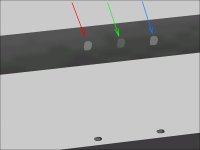
After seeing the nice clear domes on your "Space Ship", I thought that perhaps it was worth giving Alpha Transparency offered by Aircraft Animator another try.

The first task was to do a side by side comparison with my current milky white canopies. I had pieces of my pilot in the "Workshop" project which is where I often go for quick tests where the results will not be saved.

The Pilot's head was set three different ways:
1. Component colour set to Transparent [x] Light Gray.
2. Speed Below 180 knots Transparency
3. Speed Below 179 knots Alpha Transparency

Option 2 would also allow me to colour the piece with a semi-transparent texture. Hubbabubba and I had discussed this years as a solution for creating a complicated outline on a landing gear strut without using up a lot of resources. More recently, we also discussed this in relation to the rear wheel well on his Jeep.

There is also the option of naming the piece "Transparent-Something" in Aircraft Factory 99 which would allow the Index 0 colour in the palette of the texture to display as transparent. I tried this with success in the SBD-3 Dauntless Dive Brakes and Flaps, but it would not be useful here because although we wish to be able to see through the piece, we don't want it completely invisible.

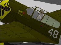
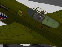
The screenshots show the various options used on the Pilot's Head.
The standard version and "Speed Below 180" look nearly identical (and examination of the SCASM code tells us that they are entirely identical).
Note that the Alpha Transparent version casts no shadow.

The remaining screenshots show the two options used on a P-40 Canopy. I am not sure which I like better on this aeroplane.
I will certainly use it at least for development on the Lightning.

- Ivan.
 

Attachments

  • Transparencies.jpg
    Transparencies.jpg
    21.2 KB · Views: 0
  • CanopyStandard.jpg
    CanopyStandard.jpg
    50.2 KB · Views: 0
  • CanopyTransparent.jpg
    CanopyTransparent.jpg
    49.3 KB · Views: 0
  • DauntlessFeathers1.jpg
    DauntlessFeathers1.jpg
    19.7 KB · Views: 0
  • DauntlessFeathers2.jpg
    DauntlessFeathers2.jpg
    107.9 KB · Views: 0
Throttle Efficiency

Hi Ivan,
Your musings do make sense, that VE is only a part of what seems to be reflected in the Throttle Efficiency table. Anyway, it´s getting better with the .air file I´m working on.
The thing with the 267 hp high-comression engines is that the rated horsepower is only available as of a given altitude, in this case 4300 ft. Thus only 60% should be available at sea-level, and proportionally 10% more more until 4300 were reached. Theretically it works in the FS98 .air file by increasing the Hp to 307 in the .airt file, and the pilot couldn´t use more power at low altitudes because of gates on the throttle that the navigator took away as they climbed. But for simming this is so cumbersome, that the turbocharger parameter in the .air file does this for you, supposedly giving you the 267 hp only at altitude.

The FS2002 airfile that I have for this has the folowinh parameters:
Turbo/Supercharged=TRUE(1)
Manifold pressure Max (inches)=30
Supercharger Low altitude boost related=5
Boost Gain=0
Critical altitude=4300
Emergency power=0
etc.

But, the engines are too weak in CFS1.

In my opinion there´s a mistake in this as there should be no boost at lower altitude than the critical - quite the contrary, and the boos gain should really be set (maybe to 5) to enter into effect as of the critical altitude.

So I switched the low altitude boost related with boost gain, and with double the manifold pressure, I seem to be getting where I want.

Would you also agree?

Incidentally, like you suggested, it does work better with the throttle efficiency at 0.98!!

Cheers,
Aleatorylamp
 
Transparencies

Hi Ivan, again!
Transparencies can be a bit of a muddle, because normal ones are sometimes too milky if using transparent grey, so I prefer dark grey, but could be too dark for some people´s liking...
Alpha transparencies on the other hand, are much more realistic, they look so much more "elegant", although they sometimes might apprear a bit too attenuated - so depending on the model, I use one or the other.
Cheers,
Aleatorylamp
 
Throttle parameter progress

Hi Ivan:
I´m progressing at a reasonably satisfactory pace:
The FS2002 FD proved useful only for the Manifold pressure and propeller parameter settings. I was hardly getting enough take-off power, and Hp got less with altitude instead of increasing. Changing the propeller parameters proved confusing, so I kept the existing ones. Funnily enough both the ones in the FS98 engine section and the CFS engine section affected Hp and RPM, and they are rather different from each other!

Anyway, the following made things better:
- Manifold Pressure=31.6
- Supercharger low altitude boost=0
- Boost gain=4.2

This gave all quite OK results at Sea-level, where the real plane could only perform at 70% or so.
Idle: 485 RPM
Take-off: 190 hp at 900 rpm,

Lift-off OK at 48 kt
Expected climb rate at 51 kt

However, at 4300 ft rated altitude, level flight performance was low, but at least I was getting an an increase on the Sea-level readings: 225hp at 1045 rpm at 70 kt.

I´m aiming at 73 kt, 1450 RPM and 267 Hp, at 4300 ft, but further adjustments on the manifold pressure and boost gain increase the sea-level performance, so it´s not as good as I´d thought.

Note: I had to edit part of this post because some results were wrong - some .air file changes seem to need a CFS1 re-start, not only re-loading the plane. I do apologize!

Cheers,
Aleatorylamp
 
Last edited:
Big Zeppelin Engines

Hello Aleatorylamp,

I took the parameters you gave earlier and threw them into my Eindecker AIR file and with some quick mods to the Throttle table got nearly what I wanted for output. Now I just need to know what the target is again.

1450 RPM maximum,
267 HP at 4300 feet.
??? HP at sea level?
??? RPM at idle?

I used 29.92 inches for sea level pressure but this will need adjusted when I know what the target HP should be.
I still need to re enable trim for autopilot in the Eindecker to test.


I will edit further when I know the other numbers.

One other thing, your RPMs are way low but that is probably because you are having a mismatch between you Engine / Propeller and Table 512 for Power Coefficients.

-Ivan.
 
Last edited:
Hi Ivan,
That´s very good of you indeed! Thank you for your cooperation.

I have just discovered contradictory information as to the restricted sea-level horse-power of these engines. I was aiming for 187 hp, but unfortunately there is indication that it could be more like 225 hp.

I´ll explain:
On one hand, a 30% reduction is mentioned in my documentation by the author of the FS2k2 FD some years ago, leaving 187 hp, which however won´t tally with the generally accepted convention of a 3% loss of power per 1000 ft.
On the other hand, the same author mentions an example of an engine with 215 hp at 5000 ft being limited to 180 hp at sea level, which would be more in accordance with the 3% loss per 1000 ft. convention.
With this reasoning, the 267 hp at 4300 ft engine should be limited to only about 225 hp.

I was reading elsewhere, that the Zeppelin engines would be reliable on the airships as they would usually operate at a constant 800 RPM, but these engines would give trouble if stressed for prolongued time at 1200 RPM or more. Possibly the 70% resriction mentioned before would be an additional measure to protect the engines from damage below the rated altitude. That´s why I was aiming at 187 hp at sea-level in my .air file.

However, after seeing the contradiction, we should probably go for 225 hp.

The idle RPM specified seem to have been about 400 to 450 RPM, but 485 would be OK as simulators seem to have some trouble with low RPM values.

You mention my RPMs are way low but that is probably because I´m having a mismatch between my Engine / Propeller and Table 512 for Power Coefficients. I´ll try to see where the flaw is. With one thing and another, it is getting a bit difficult.

Thanks a lot for your on-going help!
Aleatorylamp
 
Last edited:
Big Zeppelin Engines

Hi Ivan,
Further to my post on the sea-level power of big Zeppelin engines.
I am probably under a misconception: Have I erroneously been taking for granted that the 70% throttle limitation means a 70% power restriction?
The 267 hp at 4300 ft engines had to be operated at 70% throttle (not 70% power!!) at sea-level, which could well mean a sea-level restriction to 225 or 230 hp, and not 187 hp!

Do forgive me for the possible confusion this may have caused.

As regards the propeller: In reality this was a 14 ft, 2-blade propeller, but apparently to get the correct thrust in the flight simulator, 11.2 ft have to be used. I left the propeller settings as they were in the FS2k2 .air file, as well as table 512, (written for this plane by an FS2k2 simmer some years ago). The readings I was getting using the 512 Tables from the P51D, P47 and even the Hurricane, were giving me bad results, and I wouldn´t know how to edit this table.
What could be done about this?

Cheers,
Aleatorylamp
 
Big Zeppelin Engines

Hello Aleatorylamp,

First of all, let me state ahead of time that many things I post here are just opinions from having tweaked CFS Flight models for a while. I often state opinions about things I have never tried but seem consistent based on things I HAVE tried and how I believe things work.

First of all, your 3% power loss per 1000 feet is for decreasing engine power with increasing altitude because of decreasing air pressure / density.
Thus 267 HP at 4300 feet corrected to 307 HP at SL sounds correct.

This is a bit of a rehash of an earlier thread called "War Emergency Power" but here goes.

My understanding of the operation of Aero engines is that they have generally three or four ratings we should be concerned about:
1. Economy Cruise - The engine should be able to run at this power rating pretty much as long as there is fuel and oil. In reality this may be two ratings. One might be for lowest rate of fuel consumption and the other would be for greatest range.
2. Maximum Continuous - The engine should be able to run at this power rating as long as there is fuel and oil. This is the highest power rating that may be used without time limit. It may not be very economical in fuel use.
3. Military or Rated Power - This is a higher power level that will certainly have a time limit. This may be a "Climb" rating. Typically this rating is around 30 minutes.
4. War Emergency / Emergency / Take-Off Power - This rating is only permitted for very short term use. Typically the time limits are either 1 minute (Take-Off Only), 5 Minute (as we see in the stock P-51D), 10 Minute as we see in other aircraft. It may be longer, but CFS only offers 5 Minute or 10 Minute enforced limits. This power level may require the use of an anti-detonant such as Water, Water & Methanol, or even Additional Fuel.
CFS also has a non-anti-detonant "Supercharger" WEP that allows for increased boost for 5 Minutes 10 Seconds of cumulative use before severe engine damage.

The reason I bring up the subject of WEP is that I believe your engine power ratings / settings are not consistent.

The 267 HP / 1450 RPM @ 4300 feet appears to be a full power rating. It probably does not require a anti-detonant, but does appear from the discussion to be restricted use because of possible engine damage. Can this be considered a WEP rating?

There appears to be a much lower power rating at sea level and for take-off. The question is what throttle RPM settings are used and what the power output should be. Is that a Military or Emergency rating?

Note that the four ratings I listed may often have different names and exact restrictions depending on nationality and sometimes even on the branch of service. Some of these are pretty hard limits in that the engine really may self destruct with prolonged use and some of these limits may be pretty much ignored with no real consequence. They are written in the aircraft manuals but often are the choice of the engine manufacturer who is trying to guarantee a certain Time Between Overhauls.

Some of these limits are because of heat rejection limitations of the cooling system or because service manuals require things like spark plug replacement after each use. Perhaps the Oil Filters need to be checked for pieces of Engine Bearings? You may make enemies in the ground crew if you use them without cause.

The big question here is what exactly are the sea level maximum power ratings and what the limitations are. Is it a procedural / operating manual limitation, or is it one of engine damage. How do you wish to enforce the limit?
I typically (in recent releases) put in some engine operating instructions in the Aircraft Check List along with other little useful bits one might find in the Pilot's Manual, but except for WEP, the virtual pilot is free to ignore those limits.

Regarding Record 512, I did a few calculations with the Horse Power, RPM, Propeller Diameter, and Reduction Gear Ratios on the stock CFS flyable aircraft and put them in a spreadsheet. By this method, I could select a Record 512 from the stock aircraft with a Propeller Power Coefficient as close as possible to the aircraft I was building.
Sometimes this won't work though because the range between the flyables isn't really all that great. I found for example that the Junkers JuMo 213 engine for the FW 190D had a much greater Power Coefficient than any of the stockers and some other stuff such as the Nakajima Sakae engine for the Mitsubishi Type Zero is much lower.

Unfortunately, these spreadsheets and notes are all on my now deceased laptop and currently not accessible.
My suggestion here is to take the 512 Record from something like the Hurricane and shift all the columns in the spreadsheet over by one.
I personally haven't tried this, but I think it should work well enough for your purpose here.
Test things our with a Constant Speed Propeller and see what angle the simulator wants to use based on your engine / propeller combination.

Hope this helps.
- Ivan.
 
Back
Top