• There seems to be an uptick in Political comments in recent months. Those of us who are long time members of the site know that Political and Religious content has been banned for years. Nothing has changed. Please leave all political and religious comments out of the forums.

    If you recently joined the forums you were not presented with this restriction in the terms of service. This was due to a conversion error when we went from vBulletin to Xenforo. We have updated our terms of service to reflect these corrections.

    Please note any post refering to a politician will be considered political even if it is intended to be humor. Our experience is these topics have a way of dividing the forums and causing deep resentment among members. It is a poison to the community. We appreciate compliance with the rules.

    The Staff of SOH

  • Server side Maintenance is done. We still have an update to the forum software to run but that one will have to wait for a better time.

Douglas X-3 Stiletto FSX Native

Rick:

They would be flaps as opposed to slats as they do not open up an airway behind them and apparently are manually controlled separately from the TE Flaps. This allows the test pilot to carefully try out different positions and combinations. Interesting that the ailerons droop with the flap extension. This might have made for roll control at low speeds (relatively) being less agile.

The chart is also quite interesting regarding stall speeds in IAS increasing at higher altitudes. The only thing I can imagine changing significantly at altitude would be Mach Number?

Cheers: T
 
I see what they were doing. Thats no problem. It even makes sense.. So, two fuel pumps too then.. Milton, I think your turning this into an actual X-plane and not some funny shaped craft that flies through the air.. Thank you for that. We'll be able to do some very serious stuff with this.. :)
 
Rick:
...snipped...

Interesting that the ailerons droop with the flap extension. This might have made for roll control at low speeds (relatively) being less agile.

...snipped...

Cheers: T

Tom, I have not seen in docs I have anything regarding ailerons drooping with flap extension.

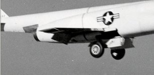
The attached picture showing the x-3 on approach with full flaps shows no aileron droop.

Also, based on pics of the aileron construction and actuating rod housings, I do no believe that is possible

EDIT: added a better pic of the aileron construction
 

Attachments

  • ail.jpg
    ail.jpg
    48.8 KB · Views: 0
  • ms-2018-mar-17-002.jpg
    ms-2018-mar-17-002.jpg
    71.9 KB · Views: 1
Last edited:
I see what they were doing. Thats no problem. It even makes sense.. So, two fuel pumps too then.. Milton, I think your turning this into an actual X-plane and not some funny shaped craft that flies through the air.. Thank you for that. We'll be able to do some very serious stuff with this.. :)

Pam,

The Op Manual shows the fuel system layout, pumps and cross-feed options.
 
Pam,

The Op Manual shows the fuel system layout, pumps and cross-feed options.

I dont believe i have the Ops manual Milton. It's not in my downloads list. However I found a copy of it on amazon for twenty bucks that i intend on buying on the first.. I'll be looking forwaard to having it as it'll help so much its not funny.. I wish we could release this, with all the manuals and documentation and research data so that enthusiasts could find something in the data that tickles their interest and simply load the plane and duplicate it.. :) Kind of like the old chemistry sets, but with airplanes..
 
I dont believe i have the Ops manual Milton. It's not in my downloads list. However I found a copy of it on amazon for twenty bucks that i intend on buying on the first.. I'll be looking forwaard to having it as it'll help so much its not funny.. I wish we could release this, with all the manuals and documentation and research data so that enthusiasts could find something in the data that tickles their interest and simply load the plane and duplicate it.. :) Kind of like the old chemistry sets, but with airplanes..

Pam,

I found a freeware version of it in the web.

I sent you the link two times by PM in early April. Was wondering why you were asking about things answered in the manual. :)

Check your PMs please.
 
Milton, I am so sorry.. your right. It was right there, and for some reason i cant imagine, i didnt download it at the time.. Thank you.. I really appreciate this..
 
i'm looking at the forward and aft CG limits and i must confess, it's got me scratching my head.. Forward limit is -2% mac while aft limit is +5% mac?? Sorry. Ice cream brain freeze here.. What?? I truly dont understand. Have I been making an incorrect assumption all these years??
 
i'm looking at the forward and aft CG limits and i must confess, it's got me scratching my head.. Forward limit is -2% mac while aft limit is +5% mac?? Sorry. Ice cream brain freeze here.. What?? I truly dont understand. Have I been making an incorrect assumption all these years??

LOL Yup, I had to ask Tom about that one. Maybe helps explain too why all the flaps are needed for a 260kias takeoff. :)

EDIT: Also, remember that flaps chart above. Three notches of flaps (as I have them setup) required to 250 kias, then one notch to 350 kias. Then you can turn her loose. Test pilots claimed if they left flaps retracted below 350, she would drop like a rock.
 
Last edited:
Indeed. especially when the estimated stall speed is 156 knots: over a hundred knots slower..

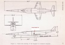
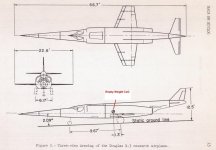
Rotation speeds are high partly because the main gear is about 1.3' behind the CoG, combined with no incidence wings, and being under-powered, you have a good mix of "can't get this thang off the ground". LOL

The Empty Weight CoG shows on the drawing at about where the 28 degree leading edges of the wings would come together on a virtual wing drawing. Remember too that the bottom is really quite flat until after the gear so you would likely get some lift there and from the 2.09 degree static stance.

EDIT: Corrected main gear location based on NACA drawing data, attached.
 

Attachments

  • x3 3view.jpg
    x3 3view.jpg
    58.4 KB · Views: 0
Last edited:
With the thin X contoured airfoil, small angles of attack could increase induced drag a lot, especially they the small aspect ratio. The straight turbojets of the era gained thrust with speed and a combination of high induced drag, possible low control and low thrust would make a high rotation speed more necessary.

When we would blast off from say Hong Kong to cross the Pacific in the 747, our minimum flaps up maneuvering speed was something like 280 knots. Even nearing Anchorage at altitude (couple hundred miles out) ATC might ask us to slow to 250 knots, they would get a little irritated when we would say "Unable".

As to the ailerons, I'll have to look through the manual again, but pretty sure I saw a photo with the flaps down and the ailerons apparently drooped.

Cheers: Tom
 
I have not been able to work on the model today but I did get a good start on the main gear last night after completing the main gear door animations and getting hinges in place.

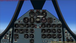
Scott Thomas has been working on the 2D panel and gauges and that is looking really good with authentic looking gauges. I'll use those gauges in the VC with some 3D gauge bezel work. I will build the VC as close to the real thing as I can with the pics I have.

I have all but one of the afterburner effects working so good progress there.
 

Attachments

  • x-3 2d panel.jpg
    x-3 2d panel.jpg
    83.7 KB · Views: 0
I bet you have these too so it's just in case: https://commons.wikimedia.org/wiki/Category:Cockpit_of_Douglas_X-3

Smooth modeling, Milton ! :encouragement:

Cheers,
Jan

Thanks Jan :)

I do have those pics, and several more, plus some graphics drawings from the manual.
Not nearly enough but we can do a reasonable likeness.
Of course, if anyone lives close to the museum in Ohio, they could get some better pics possibly, but of course that will not likely happen until after I complete the modeling. LOL
 
Rotation speeds are high partly because the main gear is about 1.3' behind the CoG, combined with no incidence wings, and being under-powered, you have a good mix of "can't get this thang off the ground". LOL

The Empty Weight CoG shows on the drawing at about where the 28 degree leading edges of the wings would come together on a virtual wing drawing. Remember too that the bottom is really quite flat until after the gear so you would likely get some lift there and from the 2.09 degree static stance.

EDIT: Corrected main gear location based on NACA drawing data, attached.

EDIT2: When setting up the NACA drawing shown above, and getting all the LWH dimensions exact, the Main Gear appears to be 2.6' behind the CoG (instead of 1.3') noted on the NACA chart. It's like they halved the main gear distance number. So, I am adjusting the model to what appears to be correct gear placement based on the drawings and the pictures I have showing the main gear struts up close to the wheel bay door cut at rear. Gear placement with respect to empty weight CoG is critical.
Unfortunately, this means redoing the main gear bay door cuts and doors, internal walls and ribs.
 

Attachments

  • x3 3view.jpg
    x3 3view.jpg
    58.4 KB · Views: 0
Well....

Got to fly the beastie, actually lining up with Muroc Dry lake and not using the whole thing was interesting!! First FSX plane I have flown that one could actually get into a pilot induced phugoid. tender touch required!!

T
 
At 29000' got Mach 1.01 in level flight, just took forever to get there. Landing wasn't too bad, but I'll guess that a chase plane was following along to talk him down on landing. Undoubtedly a pre planned approach profile was attempted.

T
 
Havent been feeling up to par the last couple days but did get a chance to take her up for a bit today. I was totally delighted to see it "misbehaving" almost on cue. She fliy's beautifully between 500 and 650 knots and is a delight. Right around 730 knots @ sea level she gets real interesting. It's like trying to swim through half dried concrete, which is a it should be. Landing was amazing. From the VC its real easy to line up on the runway, but setting it down in one piece without screwing something up is definitely an artform to be developed. Hehehe.. two mile long stopping distance.. I am quite confident that this is going to be one of the masterpieces of flight sim.. Great job Milton and team.. absolutely magnificent.
 
Back
Top