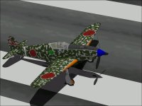
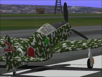
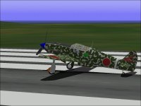
Flying Swallow

Hello Ivan,

From your comment on the Fw200 Condor thread, whose content has recently largely also been propellers, I´m glad that you have managed to get a reasonably good working propeller for your Ki-61.

Although the Ki-61 is on a different power level compared to the "Stock Griffon-Powered" Spitfire - i.e. the greatly souped-up Merlin (stock plane performances cheating again, are they?)..., at least this so-to-speak "bench test" proved that the propeller behaved very bravely, and seems to have achieved quite a congratulatable result - at least for now!

Cheers,
Aleatorylamp
 
Hello All,

One of the most serious weaknesses I have had in putting together a CFS aircraft project is in texturing the model.
The panel lines do not present any problems because they are generally pretty well defined.
One has to choose which ones to represent and which to leave out, but after a while it gets to be fairly easy though tedious.

The painting of convincing camouflage patterns has always been difficult for me. I suppose it has something to do with my refusal to accept anything that is not well defined even if it is SUPPOSED to be random.
Another issue has been the matching of camouflage patterns over multiple pieces of the aeroplane as would usually happen on the Fuselage.
Visually apparent differences in different areas of the aeroplane such as between the Wings and Fuselage also tend to bother me which is why all that appears on the model thus far for camouflage is Tail and Wings.

To make the matching easier, I thought I would try to calculate the offsets to lay out a continuous pattern over multiple pieces.
I believe the concept is sound and would make it easy to transfer a Profile Painting onto a suitable model.

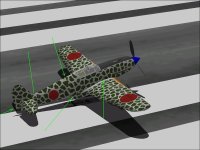
Attached is a screenshot from my first attempt which obviously failed in multiple aspects.
In this case even the scale appears to be miscalculated.

Time to go back and see where the process went wrong.

- Ivan.
 

Attachments

  • AutomaticTextureLayout.jpg
    AutomaticTextureLayout.jpg
    65.9 KB · Views: 1
Hello All,

In checking through the process for generating textures, I actually didn't find anything wrong so the best guess is that I must have copied some numbers incorrectly. This is one of the reasons I want a more automated process: To take the greatest single source of errors (me) out of the loop whenever possible.

Here is another attempt at automating the texture generation and it seems to have worked pretty well.
The Port side is also shown with the numbers not reversed so that it is easier to see that they are in pretty good alignment and continuous.

One of the things I found out when I starting looking at automatically generating texture files was that I had made a few mistakes when I was mapping textures to the model. Each Texture File is 256 x 256 pixels. The scale being used on this model is 10.24 feet over 256 Pixels which works out to 0.04 Feet per Pixel, so each Pixel covers an area of 0.48 x 0.48 inch. In places I could not tell visually but could tell once I had done the calculations that I was off by 0.02 feet (1/2 Pixel) which means that there is occasionally about a 1/4 inch misalignment between adjacent textures.
Hopefully I will remember to correct this when any other updates are made to the model.

Time to go back and see if I can get the camouflage texture looking the way I wanted.

- Ivan.
 

Attachments

  • AutomaticTextureLayout2.jpg
    AutomaticTextureLayout2.jpg
    50.5 KB · Views: 0
  • AutomaticTextureLayout3.jpg
    AutomaticTextureLayout3.jpg
    42.8 KB · Views: 0
Hello Ivan,
For someone so un-artistic as myself, textures are the worst part of modelling, and within textures, it´s camo patterns, and within those, the speckled ones, that include styles with intricate brocade or splinter patterns. They are also the most striking, though, and the model looks fantastic with them!

You seem to have found a way to get the sizes to coincide on all surfaces, which I was never able to do very well. Then, hand-matching the edges on different sections on the same surface is tedious but possible, but when one surface is up/down and the other left/right, matching the pattern gets nightmarish.

I found some photos of the Swallow where the seemingly hand-sprayed speckles were applied on the completed plane because the speckles, for example at the wing-root, flowed from the fuselage onto the wings, but other photos showed a distinct un-sprayed gap there, and in some cases the speckles on the wing were cut at the wing root, meaning either that the wing came from another plane, or that the speckles were applied before assembly. Plastic model kits also reflect both these things.

So, if life gets too difficult matching different surfaces, there is a good, real way around, because speckles didn´t always flow over! But you must have noticed this already, so there´s nothing new here...
Good luck anyway.
Cheers,
Aleatorylamp
 
Another Paint Scheme

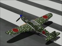
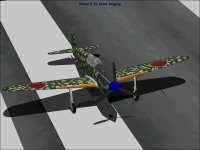
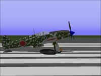
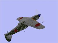
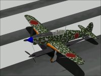
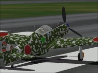
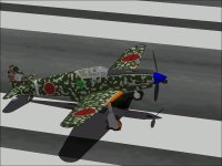
Last Night I decided to try out a different approach to a camouflage scheme.
The textures here are actually a heavily modified scan of a "Composition Notebook" back cover.
The pattern seems to be quite appropriate though it gets to be a little sloppy around the Nose section.

Unfortunately it breaks up the really pretty lines of the aeroplane though I suppose that is the point of camouflage.

The Wing Roots can be used to merge the Fuselage and Wing patterns though in real life, the exhaust stains from the engine would have turned the Fillet area gray or black and hidden any camouflage pattern underneath, so whether or not the patterns match across the major assemblies would not matter much.

As before, I am fairly satisfied with the Wings and Stabiliser but not so much with the Fuselage.
Note that camouflage was never applied to the Canopy Frame.

Time to figure out how to highlight the Katakana character on the Fuselage and design or pick some unit insignia....

- Ivan.
 

Attachments

  • Ki61_Pattern2_1.jpg
    Ki61_Pattern2_1.jpg
    63.6 KB · Views: 0
  • Ki61_Pattern2_2.jpg
    Ki61_Pattern2_2.jpg
    46.2 KB · Views: 0
  • Ki61_Pattern2_3.jpg
    Ki61_Pattern2_3.jpg
    44 KB · Views: 0
  • Ki61_Pattern2_4.jpg
    Ki61_Pattern2_4.jpg
    31 KB · Views: 1
Hello All,

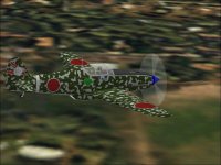
I made another try with the camouflage pattern last night.
This time, I cheated a bit:
I could not find a suitable continuous pattern for both sides, so I just used the same pattern for both sides.

In doing so, I finally figured out what was causing the texture mismatch issues.
My process is to find a continuous nice looking camouflage pattern that is about 700 pixels wide, cut it into pieces and overlay masks and then rotate the new image to be used as a texture.

(Note that the aeroplane is 29.33 feet (8.940 meters) long at a mostly constant scale of 10.24 feet per 256 pixels which makes it 733.5 pixels in length. Note also that the Spinner does not share the same texture or scale as the rest so does not need to be included.)

With just a bunch of random looking splotches and no ability to see how things overlap and fit together until it gets to the simulator, it is basically a matter of working pretty much blind until the simulator starts.

The real mismatch problem turned out not to be a Typo. It could better be described as a "ClickO".
The division of the camouflage pattern worked fine.
The conversion to BMP format worked fine.
When I did the overlay of each mask, sometimes I would forget to accept the change before continuing the edit.

Since the next step was to do a 90 degree rotation, the overlayed mask was the only thing being rotated.
The camouflage pattern underneath did not rotate and as a result did not match anything else.
With random splotches, one pattern pretty much looks like the next, but with the cheat last night, the left and right side Fuselage camouflage had to look the same. It became obvious if it did not, so I eventually saw where I was messing up.

Another item worthy of note is that although I know that my texture mapping is around 1/2 pixel or 0.24 inch away from where it should be in places, it may not always make a difference that can be seen in the model.
It is not a matter of our eyes not being able to see the difference in such a small scale; it is more a matter of the model not being generated in a way that will show such small differences:

From what I remember of SCASM coding, each vertex of a textured polygon is mapped to a pixel on the texture. Thus if the texturing scale is quite large (Greater Distance per 256 pixel bitmap), the internal conversion from AF99 to SCASM may not do well if multiple vertices are closer together than the distance between pixels. That is one problem.
Consider what this means: If your specified shift does not move a vertex enough so that it maps to a different pixel, you get exactly the same SCASM code and model as before even though your very exact specification has changed.
The second issue is that SCASM actually works on a Metric scale internally.
I believe it is 1/512 Meter resolution for the typical scale we use for these models and those are the offsets that are used from the Center of Gravity of the model to determine the location of a vertex.
So, from Aircraft Factory 99. we get to design things on a 0.01 Foot (0.12 inch) grid that then gets fitted into a 0.0769 inch grid and sometimes things that should be evenly spaced by the numbers in AF99 don't end up so evenly spaced when converted.

Note that the Wing Fillets are textured in a single colour without any pattern at all.
Note also that the Supercharger Intake still needs to be textured.

- Ivan.
 

Attachments

  • Ki61_Pattern2_5.jpg
    Ki61_Pattern2_5.jpg
    58.9 KB · Views: 0
Hello Ivan,
It looks very realistic, and the spread is nicely uniform and balanced. The effort seems to have been quite worth while!

Your previous speckled pattern and also this one, are the two that in my opinion look the best on this plane.

I noticed on several original photographs that there seem to have been perhaps 4 or 5 different camo patterns, some of which look terribly botched, as if the crew had done a last-minute job themselves with spray cans just before covering the planes a bit with palm leaves!
Cheers,
Aleatorylamp
 
Hello Aleatorylamp,

I am fairly pleased with how the camouflage turned out.
I still have trouble with random patterns. It probably comes from my obsessive compulsive side which drives me to try to make things "exactly" as I think they should look. When there is no "exact" and no distinct "should look", I have difficulty because I can't really tell when I am done or where to improve things.

The Kawasaki Ki 61 was completed at the factory and painted with national insignia, IFF stripes, various stencils, and I believe they typically had a red star around the wing gun openings. That was it.
The appearance would be pretty much like the overall Gray / Natural Metal finish that I had when this painting exercise began.

Most Ki 61 would have been crudely painted in the field by whatever means the locals could come up with.
Sometimes the appearance was good. Sometimes it was a mess. Sometimes they masked around the factory paint. Sometimes they just painted around the factory paint in a very crude manner.
This crude painting method is probably why the canopy frames were never painted; it would take too much effort to mask around the canopy glass.
Some of the camouflage looked a lot like it was done with a broom or mop.

From what I have seen, the unit markings were generally VERY well painted as were additional decorations such as stripes and lightning bolts or kill markings and other personal emblems.

I am sure some of the personnel in the field masked and painted carefully around the insignia and the home defence aircraft such as from 244 Sentai tended to be painted very precisely.

I don't think my camouflage pattern is all that realistic looking but the look I was trying to get was that of the aircraft that were painted with lots of overlapping green stripes with a spray gun. There were some gray patches left over but they tend to be much smaller than what I have here. (No, I did not contradict myself. I don't think it is particularly realistic but I still like the appearance.)

My current task is to go back and edit the flight model to improve the handling characteristics.
By reputation this aircraft and its descendants were some of the nicest handling of the Japanese fighters and right now, this bird does NOT handle all that well.

An accelerated stall is absolutely vicious and a snap roll happens often without even trying. Low speed control is quite poor, and controls in general is not very precise.
This part of adjusting flight models is actually quite fun because it isn't just a matter of flying on autopilot and recording numbers.
As I mentioned in the past, my test is to see if I can fly Figure Eights through the base of the Eiffel Tower very easily. With my P-40s and FW 190A, this is very easy. With the Hien, it isn't easy at all but it should be.

The negative curves in the Power Coefficient Table should also be adjusted a bit in my opinion. You probably don't know this, but the ones in your Two-Pitch propeller probably make more sense than what I currently have in this AIR file.

- Ivan.
 
Hello Ivan,
OK, so that clarifies why there so many different colour-scheme qualities on these planes. The impression I was was getting was not totally off then!

I like your first speckled colour scheme best, but it would also be the most difficult pattern to match at the joints between two surfaces, and the second one seems to work better there. The second one also looks clean and business-like!

Interesting, the handling qualities you report for this aircraft. That would certainly be certainly one of its attractive qualities, apart from the superb looking lines. I hope you get the behaviour where you want it!

Cheers,
Aleatorylamp
 
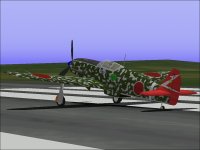
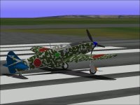
Japanese Army Air Corps Markings

Hello All,

It has been a while because I had to do a LOT of reading to figure out what the standard markings for a Japanese Army Fighter should be.
There are apparently a LOT of rules and almost as many exceptions to those rules.

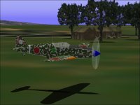
As noted earlier, the Camouflage pattern is much neater than it would normally be in the field which is where most of the aircraft were painted.
This COULD HAVE been done by some obsessive mechanics who spent way too much time masking off the factory markings before painting.

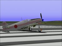
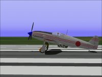
This particular aeroplane has had the national insignia on its Fuselage applied slightly larger and lower than was typical. The specification for this model was for the insignia to be 600 mm in diameter with a 75 mm white border if there was any border painted on at all.
On a light coloured aircraft, there would usually have been no border at all but the appearance is suggested by the masking before painting.

The standard factory overall finish was clear lacquer on upper surfaces and bare metal on the lower surfaces.
Some photographs appear to have the aircraft in overall light gray but I don't know if this was an effect of weathering on the lacquer or actual gray paint.

Most Ki 61 carried a white stripe on the Fuselage just ahead of the tail surfaces. This was the typical marking for a fighter aircraft, but some aircraft did not have the "combat stripe" at all or on occasion had it in other colours.
A multi coloured strip typically indicated other service roles such as test / experimental / training but there are also fighters carrying multi coloured stripes.

A wide white stripe would be painted ahead of the national insignia, if it were the Squadron Leader's aircraft.
Aircraft were generally shared between pilots but some were assigned to a particular pilot and would carry personal markings or emblems.

The Sentai emblem was typically painted on the Fin and Rudder and each Sentai (made up of 3 squadrons or Chutai) would typically have its own symbol though each Chutai within the unit would have the symbol in a different colour.

The biggest problem I ran into here was that although 10.24 feet / 256 Pixels is a very fine scale for Combat Flight Simulator, it does not allow very fine detail to be painted.
My original idea was to include a typical Japanese Chrysanthemum but when reduced down to the 30-35 Pixels available on the Fin, it more like a gray blur. A Plum Blossom (Ume) crest (Mon) was also considered and I am still working on that idea.
My children told me that the first versions looked more like a reel of movie film!

The emblems for the 19th Sentai and 68th Sentai were fairly simple so I just used those symbols for now.
The 244th Sentai markings with Red or Blue Tails are the typical markings seen on artwork depicting the Ki 61 so I am reluctant to go down the path of least originality.

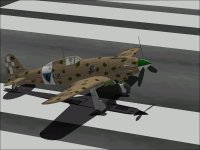
Also included is a screenshot of my Macchi C.202 Folgore that was released a couple years back. My preference is for markings with the style typical of the particular air force but not representing any actual historical aircraft or unit. I do not believe the Squadriglia emblem on the Folgore was ever carried by an actual fighter.

- Ivan.
 

Attachments

  • Ki61-68Sentai.jpg
    Ki61-68Sentai.jpg
    54.6 KB · Views: 0
  • Ki61-68Sentai2.jpg
    Ki61-68Sentai2.jpg
    81.4 KB · Views: 0
  • Ki61-19Sentai.jpg
    Ki61-19Sentai.jpg
    52.6 KB · Views: 0
  • Macchi202.jpg
    Macchi202.jpg
    55.5 KB · Views: 0
One Fish, Two Fish, Red Fish, Blue Fish....

I decided to give a try at the path of least originality just to see how difficult it was.
(It turned out to be pretty simple.)

As usual, the most difficult part was in drawing the 244 Sentai emblem.
There appear to be two little yellow patterns on top of the white flash.
The lower pattern is obviously a yellow 5 point star, but I can't really tell what the upper pattern is supposed to be.
What is drawn here is just a "best guess" at what I believe I am seeing.I

Attached are screenshots of the Red and Blue Tail versions.
I simply do not like the "White Bandage" stripes under the national insignia that were typically worn by Home Defence aeroplanes, so I did not put those on any of these paint jobs.
Note that there were also aircraft with just the 244 Sentai emblem over camouflage and others with the emblem over gray or NMF.

I also made a lot of tries with the Chrysanthemum because it was a part of the insignia used by many different units.
I was actually correct in my initial statement that I simply could not do it in 30-35 Pixels, so I tried for 40 pixels by first creating the image double sized and then using GIMP to scale the image down.

As can be seen from Kiku 1, the result was not so good.
The blurry center is something I didn't like but could deal with if I had to.
The big problem was that the edges were somewhat inconsistent and looked pretty bad when pasted over whatever was underneath.
It looked like it might have been done by a painter who was intoxicated. (....And No, I don't drink. ;-)
Often, working in a larger size and then reducing the image softens and blends the separations and does a pretty fair job of anti-aliasing but in this case, it did not turn out well at all.

After a few more tries, I decided to try drawing the symbol as a 39 x 39 Pixel image using MS Paint.
The result still has problems but looks good enough to use.
Note that the petals at 45 degrees are slightly too long but if I moved them by one pixel, they would be slightly too short....
The image is shown here as Kiku 2.

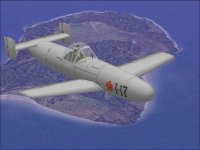
During the experiments with getting a proper Chrysanthemum, I also took a look back at what I had done with a Cherry Blossom on my Ohka 11 piloted bomb. It was a small image but looked pretty good.
As I poked around a bit, I found that the Cherry Blossom was actually used as the insignia for 45 Sentai (Bomber Regiment) which flew the Ki 48 twin engine bomber.

The Japanese Army actually used quite a few very attractive Sentai insignia, but very often these insignia are associated with Sentai in other than Fighter roles.

- Ivan.
 

Attachments

  • Ki61_244Red.jpg
    Ki61_244Red.jpg
    51.7 KB · Views: 0
  • Ki61_244Blue.jpg
    Ki61_244Blue.jpg
    66.6 KB · Views: 0
  • SmallKiku1.bmp
    157.3 KB · Views: 0
  • SmallKiku2.bmp
    157.3 KB · Views: 0
  • SakuraOhka.BMP
    72.8 KB · Views: 0
  • Ohka11.jpg
    Ohka11.jpg
    65.1 KB · Views: 0
Tuning for Maneuverability

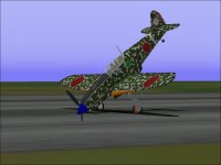
Attached are a couple screenshots of a Chrysanthemum emblem on the Ki 61.
I still can't decide what the marking behind the Chrysanthemum should be.
Perhaps a single ribbon or banner? Perhaps a Lightning Bolt?
I really should save off a few of these texture sets in case I might want to include them in the release.

Yesterday, I started the Ki 61 for better handling and maneuverability.
The idea is to improve the controllability without changing the measureable straight line performance in any way.

About a week ago, I confirmed that the zero fuel weight in the AIR file was correct.
Fuel quantity and arrangement was also checked but I am pretty sure the numbers I have are off by around 15 Gallons or so.
I don't happen to know if the Ki 61 was like many other Japanese fighters and used continuous Methanol anti detonant when running past cruise power. If so then the AIR file weight will change a bit but will be made up by the weight of Methanol.

I also checked the DP file ammunition weights which were correct.
Moments of Inertia were also within reasonable range of calculated values.

Unfortunately the firing rates of the guns was not correct.

The Ki 61-I Tei (d) had an extended nose section to allow the mounting of a pair of Ho-5 20 mm cannon in the cowl.
The free firing rate of these guns was 850 Rounds Per Minute.
By my understanding, a synchronized cowl gun would typically lose 15-20% of its rate of fire, so the Ho-5's firing rate was reduced to between 700 and 725 Rounds Per Minute.

The wing guns were a pair of Ho-103 12.7 mm guns firing explosive shells. They retain their normal 900 RPM free firing rate.

The first actual AIR file adjustment was to the Control Response records (341, 342, 343).
The result was amazing. Lining up for the base of the Eiffel became fairly easy as did quick aborts when things did not quite line up.
It was quite possible to fly Figure 8s through the base though I did not actually try.
The directional stability was still a bit too high and ruined a few passes.

Two crashes showed where there were still problems.
One issue was the loss of Elevator control at moderate to high speeds which meant that I could not pull out of a low altitude loop.
The second issue was shown when the aeroplane snap rolled as a result of an accelerated stall.

Tonight was spent making a few tools so I can compare some graphs in the AIR file.
There is still more tuning to be done.

- Ivan.
 

Attachments

  • Ki61_KikuTail.jpg
    Ki61_KikuTail.jpg
    72.2 KB · Views: 0
  • Ki61_CamouflageTest.jpg
    Ki61_CamouflageTest.jpg
    64.9 KB · Views: 0
Hello Ivan,
Your artwork is certainly looking very good. The markings are very attractive too, and will allow for more than one upload, I´m sure!

I´m glad you are progressing with the .air file, and that the model´s behaviour is fitting your expectations more closely.

Interesting, that you mention Control response Records 341, 342 and 343. I have always wondered about them, but have never more than glanced at these graphs, without daring to play around with them, as my knowledge on detailed aircraft behaviour has never been more than a general impression.

Your comments seem to indicate they could be useful to regulate manoueverability in extreme conditions, which sounds exciting! Perhaps I´ll experiment with them a bit to see how they work. I´ve just put it on my To-Do List!

Cheers,
Aleatorylamp
 
Hello Aleatorylamp,

I am still not anywhere near done with adjusting the handling.
I had actually gone a lot further than I just described, but there is at least one factor that I have not yet pinned down that seems to limiting the amount of control force that can be applied. I have a pretty good suspicion but am not sure how I should handle it to be consistent though.

By reducing the Directional Stability and reducing (!) the Rudder control, it is now much less difficult to hold the aeroplane straight on the runway even though I have done nothing to affect Engine Torque or P-Factor.

As an analogy, consider how difficult a time a swordsman would have with a blade that has been tied in a knot with the tip pointing in an odd direction. The weapon is certainly dangerous but not intuitive to use. I am doing the equivalent of trying to re-equip with a straight bladed sword of the same length. They may be the same weight and have the same reach, but one is intuitive to use and one is not.

The really surprising thing about this tuning is that I have done absolutely NOTHING that should affect the stall characteristics of the aeroplane. It still has a very sudden and vicious stall, but it is so much easier to hold it on the edge of a stall that it is not so bothersome any more. (I know the sudden wing drop and loss of control has not gone away because of the low altitude snap roll and crash when playing around the Eiffel Tower.)

There is still a lot more to fix before I can consider this project to be complete.

- Ivan.
 
The Point of the Sword

Hello All,

I believe I am finally done with tuning the handling of the Ki 61-I.... At least for the first pass.
I had a pretty good idea of what I was trying to accomplish but am still a bit surprised at how well things turned out.
I will be leaving both versions of the AIR file in the release in case anyone is interested in doing a comparison.

The basic handling modifications should have absolutely no effect on the measurable performance that was documented earlier and yet the net effect is much more effective fighter that can be flown to its limits.

In checking out the rest of the AIR file, I found that the CL Graph had a slightly lower maximum Coefficient of Lift than I would have expected and made some adjustments.
These adjustments unfortunately DO change some performance numbers.
The slightly higher CL value should slightly lower the Stall Speed to about 90-95 MPH clean.
Climb Rate should also increase slightly but not to a measurable degree by the method I am using.
The adjustment to the CL Graph in theory should affect but not significantly change the Stall Characteristics.
A Stall still often leads to a Spin but it is now much easier to stay just at the edge of the stall before loss of control.

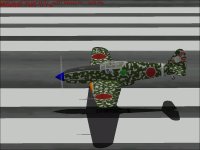
As mentioned earlier, flying through the base of the Eiffel Tower is now very easy.
Very low level flying is also very easy now. The only problem is that with CFS, there is not enough ground detail to judge altitude very precisely.

The next step in development is to program a few gauges for testing and at least one for the actual panel.

- Ivan.
 

Attachments

  • Ki81_LowPass.jpg
    Ki81_LowPass.jpg
    53.2 KB · Views: 0
  • Ki61_CuttingDaisies.jpg
    Ki61_CuttingDaisies.jpg
    27 KB · Views: 0
Abusive Testing

Some of the testing gets a little hard on equipment.
Fortunately, new Propellers and Engines are not that hard to get in the virtual world.
Testing Wheel Brakes and Scrape Points tends to get lots of Prop Strikes as does the very low level flying.

I have never quite figured out how to get the Scrape Points set in such a way that they line up with the 3D Model and still make the aeroplane sit properly.

A bit more testing and edits for handling were also done and the audio Stall Warning was enabled.
Now it is much more obvious when a low altitude stall causes a crash though to be useful, the stall warning should happen BEFORE the actual departure.

- Ivan.
 

Attachments

  • Ki61_TestBrakes.jpg
    Ki61_TestBrakes.jpg
    46.2 KB · Views: 0
  • Ki61_CrashTest.jpg
    Ki61_CrashTest.jpg
    34.6 KB · Views: 0
  • Ki61_LowReference.jpg
    Ki61_LowReference.jpg
    52.6 KB · Views: 0
Manifold Pressure Gauge

Hello All,

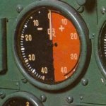
The last couple evenings have been spent working on a Manifold Pressure Gauge for the Ki 61.

Getting a clean image was not easy, but I believe I have sufficient information to program such a gauge now.
This gauge apparently was manufactured with many slight variations in the markings though the general appearance and colours were very similar. The Positive boost side was Red and the Negative side was either Black or Dark Gray.
The same instrument was used on many different aircraft of the Japanese Army but as usual, if the Army used it, the Navy did not.
This gauge was used on the:
Army Type 1 Fighter - Ki 43 Hayabusa (Oscar)
Army Type 2 Fighter - Ki 44 Shoki (Tojo)
Army Type 3 Fighter - Ki 61-I Hien (Tony)
Ki 45 Toryu Twin Engine Fighter (Nick)
Ki 46 Recon Aircraft (Dinah)
Ki 48 Twin Engine Bomber (Lily)
and probably others that I don't know about yet.
I came across images of these aircraft while searching for a clear image of the MP Gauge for the Ki 61.

Attached is an image of the instrument from the instrument panel of a Ki 46.

So far, I have finished the images for the Gauge Face and the Needle but have not yet done any programming.

- Ivan.
 

Attachments

  • Ki46Dinah.jpg
    Ki46Dinah.jpg
    123.4 KB · Views: 0
More Reliable Information

The standard factory overall finish was clear lacquer on upper surfaces and bare metal on the lower surfaces.
Some photographs appear to have the aircraft in overall light gray but I don't know if this was an effect of weathering on the lacquer or actual gray paint.

Sometimes even information from books is not terribly reliable.
The source of information for the standard factory finish being clear lacquer was from the same book that seemed to give good information about the standard markings.
This information is disputed by a discussion at the J-Aircraft site which seems to make a lot more sense.
I will paraphrase some of it here and hopefully the previous sentence can be considered sufficient credit.
Some of the following is also my own interpretation, so any misinterpretation is mine.

Pre-war research in Japan came to the conclusion that ANY coating on a Natural Metal Finish would be better than none because the reflectivity of bare metal could be seen from great distances.
The problem with clear lacquer applied to aircraft exposed to the sun is that they would turn yellow in a very short time.
This by itself is not necessarily bad but does not seem to be what happened to aircraft in the field.
Sometimes aircraft were painted aluminum, sometimes they were painted gray. Basically any paint was better than none at least on the top surfaces. High reflectivity on the underside did not seem to matter as much.

So for now (Not that it matters much for CFS Textures), I will assume that the factory finish was an overall light gray.

- Ivan.
 
More Updates

A little while ago, I did some more checking of my numbers and found that I had made a slight error in calculations.
My original listing for ammunition load for the 20 mm cannon mounted on the cowl was 150 rounds per gun.
The correct ammunition load is actually 120 rounds per gun which I corrected in the DP file but I did not update the weight specification in the AIR file.
To maintain the correct loaded weights, 31 pounds needs to be added to the Zero Fuel Weight in the AIR file.
In addition, I decided that it probably makes sense to include the Aft Fuselage Fuel Tank since it is one of the distinguishing features of the Ki 61-Id.
The extra 95 Liter (25 Gallon) Fuel Tank would add another 150 pounds to the Take-Off weight.

With an extra 181 pounds more weight, performance is expected to drop slightly, so it is time for another round of tests.

- Ivan.
 

Attachments

  • Ki61-Id_RFHigh.jpg
    Ki61-Id_RFHigh.jpg
    57.4 KB · Views: 0
Back
Top