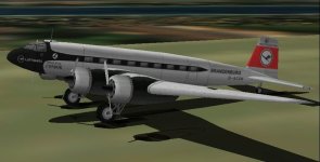
Focke Wulf Fw200-A Condor

aleatorylamp

Charter Member
Hello Folks,
Well, as it turns out, at the end this project will need an own thread, because there are a couple of things that need attention before a CFS1 upload can be undertaken:

1) - Flight Dynamics:
Although the FS98 .air file is quite good, it´s for FS98, so it doesn´t take advantage of CFS1´s supercharger capacity. It´s in the making, and there may be some issues regarding the power curve for the 720 Hp @ 2050 RPM BMW 132-G1 engines with their single-speed superchargers, that need tweaking.
Update:
It appears that max. speed was 226 mph (at S.L.? dunno...), and apparently the Maximum Manifold presure of 1.2 ATA was maintained upto 6000 ft. Doing it this way in the .air file, there are unwanted peaks of almost 250 mph at 6000 ft and 9000 ft, even reducing the 226 mph at S.L. to 221 mph.
However, using a "similar" criteria of maintaining 720 Hp instead of 1.2 ATA upto 6000 ft, then the peaks come down by 6 mph, but it is still 14 or 16 mph too high. So, it´s still on the drawing board...


2) - Virtual Cockpit:
AF99 didn´t have enough parts to make a virtual cockpit, so it wasn´t included for SF98. Given the good FS98 panel by Pegasus Design, this was a viable option. However, not so for CFS1, because with SCASM, a virtual cockpit can be made, and it will be a good idea to include one. It will most likely have to be a call in the usual position of the listing for VCockpits, to some extra parts placed at the end, similar to the Zeppelin Staaken SCASMing.

3) - Panel:
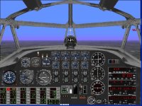
The Pegasus Design Panel is very good for FS98, but needs different instruments for CFS1. Also, I don´t know if it will be very useful having 2/3 of the cockpit shown - it makes the cross-hairs seem off centre. Hence, for CFS1, it may be more useful to have a complete and centred panel. As right hand side instruments are repeated, possibly nav. and com. instruments will be handy there. So, while I´m at it, I´m making the panel bitmap too. Here´s a screenshot of the provisional panel - still including the Beckwith gauge (dig Ivan´s new gauges!).

In consequence, this project can´t be a direct FS98 upload into CFS1, but a CFS1 adaptation, and will require a little work before it will see the light of day. I´m sure it´s better to do it better than to leave it go as it is...

Cheers,
Aleatorylamp
 

Attachments

  • Condor-a.jpg
    Condor-a.jpg
    43.8 KB · Views: 0
  • Condor-b.jpg
    Condor-b.jpg
    46.6 KB · Views: 0
  • Condor-c.jpg
    Condor-c.jpg
    88.9 KB · Views: 0
Last edited:
New Performance Data

Hello Folks,
Constantly on the lookout for more technical details regarding engines and performance of the early civilian version of this aeroplane, Fw200-A, I have slowly been able to complete the picture. It appears that what was given initially as top speed of 224-226 mph, is more likely to be a max. cruising speed, and that the real top speed was 245-250 mph, at 6000-9000 ft.

The early Fw200-B version had a somewhat more powerful engine - 850 Hp, for which more exact details are available.
What is interesting, is that by extrapolating information from here to the 720 Hp engined version, the results are very similar to the newly found data, and would actually confirm it.

So, the .air file I am working on at present is surprisingly nearer to the specified performance than I thought, which is good.
Cheers,
Aleatorylamp
 
Hello Folks,
The panel for the Condor now has its set of engine gauges comnpleted with metric oil temperature and pressure and EGT/CHT gauges. The gauges are originally the default FSFS Cessna oil and Cessna egt-cht ones, but with a metric scale and German working on the dials. The panel in general follows the layout of the original airplane for the pilot´s position, and on the right, for the moment at least, is a functional radio operator/navigator´s position. Here´s a screenshot.
Any suggestions will as always be very welcome!
Cheers,
Aleatorylamp
 
Hello Folks,
After extensively testing four or five different parameter combinations in the flight model, I´ve arrived at (in my humble opinion) very satisfying results, where the aeroplane´s specifications compare quite well to the performance of the model.

FW200-A Condor Specifications:
-------------------------------
Engines: BMW 132-G1 9 cyl Radials
Max. Power: 720 hp @ 2050 RPM (5 min.)
Cont. Power: 550PS at 1930 RPM

Full 1.2 ATA altitude: 5905 ft
Specific Fuel consumption: 230g/PSh
I haven´t tested this, and for the moment, there´s no gauge except Mr. Beckwith´s stack.

Ceiling: 19000 ft (because of max. possible altitude without pressurized cabin).
Max. Speed: 226 mph at S.L.
Max. Speed: 242 mph at 6000-9000 ft
Cruise: 208 mph at 3280 ft.
Cruise: 217 mph at 12467 ft
Eco cruise: 197 mph n.a. ft.

Flight Model performance:
-------------------------
Max Speeds:
-----------
SL.300ft:226.4 mph, 720 hp, 34.9 MP (1,2 ATA)
6000 ft: 242.4 mph, 754 hp, 34.7 MP (1.2 ATA)
9000 ft: 241.8 mph, 674 hp, 31.1 MP (1,03 ATA)
12500ft: 239.7 mph, 582 hp, 27.0 MP (0.94 ATA)
15000ft: 239.6 mph, 521 hp, 24.4 MP (0.85 ATA)
19000ft: 237.0 mph, 435 hp, 20.7 MP (0.72 ATA)

Cruise Speeds:
--------------
The model´s cruise speeds compared to the specifications from the Pilot´s manual, occur at slightly different Manifold Pressures.


S.L. 328 ft:

Cruise spd. Spec: 201 mph, 0,98 ATA. - Model: 0.9 ATA
Eco-Cruise. Spec: 186 mph, 0,74 ATA. - Model: 0,77 ATA
3280 ft:
Cruise spd. Spec: 197 mph, 0,94 ATA. - Model: 0,78 ATA
Eco-Cruise. Spec: 186 mph, 0,89 ATA. - Model: 0,70 ATA
9800 ft:
Cruise spd. Spec: 191 mph, 0,72 ATA. - Model: 0,61 ATA
12500 ft:
Cruise spd. Spec: 217 mph, n.a. ATA. - Model: 0,74 ATA

I would say the .air file is OK like this. Any comments will of course be appreciated and very well taken into account!
Cheers,
Aleatorylamp
 
Cruise Throttle Setting

Hello Aleatorylamp,

What is the RPM you are using for maximum power and how much lower is the RPM for your cruise setting?
I suspect that might be the reason your throttle settings need to be reduced to match.

- Ivan.
 
Hello Ivan,
Thanks very much for your comment.
The revs stay on 2046 RPM all the time... I think we had this before on other engines.
For cruise speeds, e.g. 72% throttle or even 60% or 50% throttle has to be set, but RPM always goes back to 2046 or 2045 RPM.
This would be because of the C.V. propeller, I suppose?
Can this be corrected? At cruise it should really go down to 1930 RPM or so.
Possibly we are talking about having to use high and low manually set propeller pitches that these early Fw200-A units had. I just found out about that yesterday, going through all the pilot´s manual I had in the FS2002 version of the plane that I finally dug up from an old hard disk.

The better performing BMW 132 L and H versions of the same engine were installed on the FW200-A later, for the Fw-200S (previously an A unit) and for the Fw200-A0 series. One of the differences was that 800 Hp could be wrung out of them for 1 minute and for 5 minutes, but mainly it was the CV propeller. Early A units with the previous BMW 132-G1 engines had props with only 2 pitch settings: high and low angles. I would expect that this made a greater difference than the 80 hp take-off power increase.

Cheers,
Aleatorylamp
 
Last edited:
Back to square one

Hello Ivan,
It´s nerve wracking sometimes.
For the umpteenth time I had put in the ungeared propeller, but the gearing always managed to creep in again because of the 4 different .air files I was gauging against each other. It was also only very recently that I found out that the BMW 132 G1 had ungeared propellers, slightly smaller, and that subsequent versions of this engine all had geared ones that were a bit larger!

Update:
The whole engine seemed screwed up, but even the torque won´t need to be adjusted!

What I noticed was that RPM take longer to build up, so it was a matter of minimum propeller pitch, that had to be less.
For the moment, it seems to be getting fixed by lowering the minimum pitch from 23 degrees to 15.
Then, for higher altitudes, I think I may reduce the 65 degrees to about 50, and we´ll see what happens.

What a mess.... but it´s now less messy after the initial shock!
Cheers,
Aleatorylamp
 
Hello Aleatorylamp,

I think we have had this discussion a few times before and I THOUGHT you understood what I was trying to explain.
1. Set Engine Power with a constant speed propeller and whatever gearing it takes for your engine to reach full RPM.
Easy ways to handle this are to either change the gear ratio or the propeller diameter.
Consider this the Bench Tuning for the engine.
2. Set the Gear Ratio, Propeller Diameter and Propeller Pitch Range.
This is the reality part. The numbers are what they are.
3. Use the Propeller Power Coefficient Table (Record 512) to adjust the RPM response of the engine.

Building a Record 512 is a bit of a pain. I am actually trying to do some programming / spreadsheets to help create this table.
If you don't know how to do it (I still fall into this category), then pick a matching propeller table based on the power coefficient of the stock aircraft that best matches your particular aeroplane.

I currently have a project that needs this kind of work (Kawasaki Ki-61-Id) and a proposed project (Ki-43-I Hayabusa) that will depend on altered 512 Tables to behave properly.

If you can't get there, you can do as I have done and delay the release of the project or an alternative method which might help is to adjust the Propeller Diameter until things behave properly. I don't like that idea myself but am willing to wait until I have properly addressed the problem.
Being able to finish a project is my incentive for addressing the problem.

The bottom line is that tuning engine power really does not address the problem you are encountering.

- Ivan.
 
Hello Ivan,
Yes, sorry! A short while later I remembered the discussion, and I realized what was causing the MP differences I was getting at different cruise speeds, compared to spec MP. But, I´m afraid I´m not about to fiddle around with the 512 propeller table entries.
I remember trying once or twice and only making things worse!


I found the P38 prop tables work better with the Do17-z2 and the FW200A. Then, the P51d tables did better for the Baltimores, as the props were considerably larger.

Before, I had 2.088 gear ratio (of the P51d), and 10.5 for the prop diameter, but of course, it is different now with the ungeared, 9.7 ft prop. The gearing seems to have a greater effect in this case.

I did the engine bench tuning and last night I managed to get the RPM correct again, and also had to lower zero lift drag for correct S.L. performance. Now of course, higher up it´s different, and it looks like the discrepancy with the cruise speed throttle settings is going to get worse.

So... Thank you very much for reminding me about playing with gear ratio and prop diameter as a get-by alternative to altering table 512 - I ´ll see how it goes.

Cheers,
Aleatorylamp.
 
Propeller Table 511 and 512 surgery?

Hello again, Ivan!
First I established the correct 226.8 mph performance at S.L. for the "new" older gearbox-less engine and smaller prop.
Then at 6000 ft I got an excessively high performance - 255 mph instead of 242 mph, which could almost be corrected by pulling down the propeller pitch levers all the way. I got 243 mph.

So, after two cups of tea I had a look into Propeller tables 511 and 512 trying to see where the differences were for the P51d and the P38, for example, and was no wiser after that. Some places in the table are identical and others different, and it means nothing to me.

Then, after another cup of tea I had a look into the AAM Graph depiction of these two tables, of which I made screenshots.
Unfortunately I am still none the wiser.

However: Manually, all the lines in the graph can be selected and their individual positions can be moved up or down by mouse.
In general, the idea you are putting forward is to try to manipulate the graphs to perhaps be able to adjust correct performance at altitude.

So here comes my stupid question and conjecture:
Which parts of the graphs would need intervention, and in which direction?

In theory, at altitude and with speed, the propeller is at a greater angle, and this angle would have to be made less powerful, but how? My conjecture would be to try and lower the 20, 25, 30, 35, 40 and 45 degree graph lines a bit? Does this make sense?

Update: I´ve just done this, and it got worse - the opposite happened:
S.L. performance went UP from 226.8 to 241 mph and 6000 ft performance went UP from 255 to 261 mph.
So obviously it wasn´t the thing to do, was it? Hmmmm.... but, I´m learning...
NOTE: The middle screenshot is the modified table 512. The one on the right is the original, unmodified one.

Update 2: The puzzle unfolds with increased complication:
Raising instead of lowering the graph lines obviously has the opposite effect, lowering performance including at S.L.
However, if the 20-degree graph line is left untouched, it reduces speed more at altitude and not so much at S.L.
Looking closely at the Beckwith Gauge, the propeller advance ratio range for full power depending on altitude is rather small - between 20 and 22 degrees or so.
For cruise speeds, advance ratios seems to be around 19 degrees. To adjust throttle settings here would require changing the 15 and the 20 degree line too.. But this will also affect Take-off Power and S.L. Performance, won´t it?

I realize that you have not yet concluded your own experiments on the subject, but perhaps there is a general idea that I could try and follow. ...Maybe I´m letting myself in for something quite out of my reach.

Thank you again for your continued coaching, and in advance for your possible views on this difficult subject.

Cheers,
Aleatorylamp
 
Last edited:
Hello Aleatorylamp,

This is one of those tuning tasks that I know how to do but don't really have a set of step by step instructions to give you yet.
For me, this task is one of those edit and test cycles that needs to get repeated about 50-100 times to really get things right.

First of all, you need to figure out what results you are expecting.
How does the propeller behave under load?
Does it lug or does it hit full RPM pretty early in the Take-off run?

I have done no research on the FW 200 other than looking at its engine parameters and power curve (for the Fafnir versions) when trying to tune the Dornier 17. I don't even know what its performance was or what the RPM range of the engine was, so any advice I give is a guess.

Here are a couple observations from what you have posted thus far:
The maximum propeller pitch you are getting in flight of 19 degrees at cruise and 20-22 degrees at full power seem to be way too low.
This means that your Table 512 for Propeller Power Coefficient is for a Propeller / Gear combination that is for a much more powerful engine that you actually have.
You can work your way around this in a couple different ways.
One would be to find a Table 512 record from an aeroplane with a lower Power Coefficient. (Perhaps a Cessna 182?)
I have only calculated the values for the CFS Stock Flyable AIR files and I am guessing what you have is much lower powered.
Match based on Power Coefficient and not just propeller diameter as I believe you are doing.

The second method is to simply reduce the Propeller Diameter in your AIR file.
Yes, this is a physical specification, but when you can't generate a new propeller table, that may be the way to get around things.
I use this method to fine tune the response and then edit the Power Coefficient entries to reflect what the diameter change would have done.
Tuning a couple AIR file parameters beats the heck out of pulling the table into a spreadsheet and then putting it back in.
In theory, this should result in an exact match but I have found that it generally is still a bit off and needs fine tuning of a few values in a spreadsheet but it saves a lot of cycles in my opinion.

To get the actual engine power, RPM, and propeller pitch values to look at, you may need to play with the Airframe Drag and Propeller Efficiency in Table 511.
Use a throwaway version of the AIR file for this experimentation because most of those changes will be garbage for a real AIR file; You would be doing this to create test conditions for tuning Table 512.

Once you get a proper response from your propeller both at Sea Level and at altitude, then tune Table 511 entries to get proper thrust to achieve the performance you want.
You should already have the RPM / Advance Ratio / Pitch combinations from testing that was done for Table 512.

After that, it is a matter of smoothing out the curves so the graph is "continuous" and does not have odd peaks and dips in strange places.

This is actually quite a tedious exercise and there probably is a better way, but this is what I know how to do.
I was planning on programming a bunch of tools to make this process easier and more predictable, but that is on hold while I am working on gauges.

Hope this helps.
- Ivan.
 
Hello Ivan,
Thanks for your detailed explanation, which i have been trying to figure out, but it´s too confusing.

The prop takes a while to accelerate during the take-off run, so I´ve reduced prop inertia and will have to do so some more.

Then, as there´s no Cessna 182 prop table to be found, I´m trying to understand how to do the prop reduction manouever...

I´m afraid you credit me with more understanding than I have, and I´m missing details as to what to do.
What data is to be obtained from a test with a smaller prop, and what do I have to do with it, and then, what to do with table 511 to be able to see what data?

For example, with table 511 I reduced the peaks in each line so that the peak happens in the column to the left, supposedly trying to reduce propeller effectivity, and in table 512, I tried to raise the graph lines corresponding to the propeller advance ratio readings that were giving too high a performance, in the hope of lowering it. But, I don´t really know what I´m doing.

Then, with a 6 ft prop, at S.L. advance ratio range was 30-45 degrees, depending on throttle setting, and at 10000 ft, 40-50 degrees. Hp also changed, but not too much. So, supposing this were useful data, what is it telling me that I don´t understand?

Sorry, I´m quite lost...
Cheers,
Aleatorylamp
 
Last edited:
Hello Ivan,
Given the complication involved :dizzy:in altering tables 511 and 512 with any degree of success, I think I´ll go for the smaller prop alternative that you had initially suggested, and tune performance accordingly :untroubled: .

However, to use information obtained from such an experiment for alterations in the prop tables is unfortunately way out of my scope, at least for the moment.

So: If a geared 10.5 ft geared prop was already giving me reasonably accurate results, an equivalent ungeared smaller prop (the real one was two-bladed and 9.7 ft in diameter) would in the simulator possibly be about 7 or 7.2 ft, without me having to alter tables 511 and 512.

After initial trials with 6.2 ft and 7.8 ft props, I had the impression that I had to be somewhere in-between:
Once correct 226.8 mph S.L. performance was obtained, the 6.2 ft prop gave about 238 mph at 6000-9000 ft, and the 7.8 ft prop, 250 mph, and I´m looking for 242 or 243 mph. The corresponding advance ratio ranges also pointed in that direction.

Update: Results with the 7 ft prop:
As expected, these have been quite successful, given the circumstances.
Top speed results were exactly as planned, and cruise speed results were almost identical to those obtained with the previously larger, geared prop. For the moment at least, it can be said not to have got worse, and at least now props are ungeared! :encouragement:.
I forgot to note down the propeller advance ratios, which of course increased notably, but I can do that later if necessary.

Cheers,
Aleatorylamp
 
Last edited:
Hello Aleatorylamp,

I have actually been having a difficult time with one of the gauges I was working on and it was supposed to be a very simple one!
I actually went back to the FS98 SDK to see if I could get it working there as an alternative but the Token Variables simply do not exist there.

With the propeller tables, I am not even sure where to begin without re-stating what I have already posted before.
I believe that we first need to get some terminology straight so that further discussions make sense.
Next, we need to understand what is happening and then perhaps then you will see the way to fix the problem.
I am somewhat hesitant to volunteer to fix this issue for you because it would take away time from the gauge development path that I am on right now.
I get distracted easily and often don't return to where I was before. Smilo can vouch for that!

Descriptions (I don't call them definitions because I am not going to try to be terribly rigorous.)

Advance Ratio:
This is a ratio between the tip speed of the propeller and its forward motion.
Note what applies to calculate Tip Speed: Angular velocity - RPM multiplied by Radius
This is the Horizontal Axis of both Propeller Tables

Propeller Pitch:
This is the angle that the blade makes with rotational direction.
0 degrees would be Flat Pitch and would provide no Thrust because the blade does not "bite" into the air and push it back.
90 degrees would be full Coarse Pitch or Feathered.
Again, no Thrust because the air is being pushed in the direction of rotation and not along the axis of the aeroplane.
Flat Pitch gives the least resistance to rotation.
As the pitch increases, there is more drag on the blade because it presents a larger profile to the rotational direction.
Small angles (perhaps 15-25 degrees) does well at low aircraft speeds but as the speed increases, the angle of attack of the propeller blade becomes negative and it can provide no "Lift" or Thrust in the direction of flight.

Propeller Efficiency (Table 511):
This is a measure of how well the propeller converts Horsepower into Thrust.
The difference between Power and Thrust:
Thrust is a Force.
Power is Force * Velocity.
Thus for the same engine POWER, the THRUST decreases as velocity increases.
In theory, this would mean that with this conversion, Thrust is infinite at zero forward speed, but there is a low speed propeller theory to take care of that business.
It is actually one of the fields in the AIR file but I think it is actually not used.
Don't worry, it changes to the regular model before the aeroplane ever leaves the ground.
Note also that Propeller Efficiency should be Zero at Zero Forward Speed (Zero Advance Ratio) but it isn't.
I believe this may be another way to handle low speed propeller theory, but it matters so little, I have not bothered to test anything here.

In theory, the Propeller Efficiency should never exceed 1.0 but since we are playing with a simulator and not reality, those rules don't really apply to us Magicians.
In fact, for my version of the AIR file for Hubbabubba's Jeep, the efficiency is about 2.5 or 5.0 in various places to provide the appropriate forces that result from a Transmission Gear and Final Drive (Differential) Gear (I can't remember the exact numbers I used).
Look for typical Propeller Efficiency Table images on the Internet to get a feel for what it should look like.
Once you have done that, you will see something really screwy with the CFS Table 511s.
(I will get back to this later if I have time.)

Note also that while God helps real aircraft interpolate between different pitch angles to produce a smooth curve, WE in the virtual world have no such Luck:
Computers interpolate between points and sometimes that interpolation causes some problems.
In fact this is one of the issues I need to address in generating my own propeller tables.

Propeller Power Coefficient (Table 512):
The Power Coefficient is basically a number telling us how much resistance to rotation is given by the Propeller / Gear combination.
(Find the formula on the Internet and put it into a spreadsheet so you can experiment!)
The AIR file parameters this is dependent on are the Gear Ratio and Diameter.
....and of course Propeller Blade Pitch!
So what is Table 512 telling us? I am not all that sure I really understand it either, but this is what I believe to be true:
The values above the Zero line tell us how hard the propeller is to turn.
The values below the Zero line tell us how hard the airstream is trying to turn the propeller.

Note that Power Coefficient is just a measure of how hard the Propeller is to turn.
It has NOTHING to do with the amount of Thrust provided by the propeller.
This is why we can work on them independently even though they are pretty closely related.
So in other words, Power Coefficient could be measuring our engine trying to turn a Telephone Pole, Wooden Plank, or a Barn Door or a Propeller Blade.
It makes no difference.

Note that the formula for Power Coefficient is pretty simple. It does not take into account the number of Propeller Blades, or the Form Factor of those Blades.
It DOES however take into account the Engine Reduction Gear Ratio.
Factors that do no influence the mathematical formula are why we need to be able to tune this table.
What if we have a 11 foot diameter propeller with a 0.500 Reduction Gear?
The formula gives us a value.
The problem is that other factors are not taken into account such as "Activity Factor".
In other words, do we have two 6 inch wide Blades or do we have six 18 inch wide Blades?

So why did I tell you to change the Propeller Diameter if you can't change Table 512?
As I understand it, the Diameter change would alter the Advance Ratio values and the Power Coefficient calculation and thus makes for a propeller that is much easier to turn.
This helps match your propeller to a Power Coefficient Table that really does not fit it.

So how do you work backwards from there?
Once you get good behaviour, you see what the Thrust, Advance Ratio and Propeller Pitch are at the critical places in your AIR file and write them down.
With that information, you can go back and calculate what the Advance Ratio change would be a proper sized propeller.
Then, figure out the equivalent columns are in Table 512 and multiply through (only the Positive values) to get what your new calculated values would be.
Now the chances are that because of the changes in Advance Ratio in Table 511, you probably wan to overcompensate a bit.
For fine tuning, you can also adjust the efficiency in critical areas of Table 511 to do a direct adjustment to thrust output.

If you have followed this discussion, you have as good an understanding (or misunderstanding) of how propellers work as I do.

- Ivan.
 
Hello Ivan,
I had just finished collecting the Prop Advance ratio readings for different speeds and altitudes. I´d prepared this report just when your post arrived. Thank you very much indeed!

First of all, I am not expecting you to do the .air file for me, don´t worry! I wasn´t even thinking of it - firstly, because I´d like to do it myself if I understand how to do it, and secondly, I don´t want to bother you under any circumstances! I know what you are doing with the gauges at the moment needs concentration and time.

Your detailed answers to my e-mails are actually much more than I had expected! Thank you ever so much for your patience and time taken to explain all this to me. I will read through your post attentively and come back on it later.

For the moment, here are:
Prop advance ratios as per speeds and altitudes:
------------------------------------------------

-S.L. Take Off and 300 ft 226.8 mph max. speed:
-Initially: 15, quite quickly increasing to 25, then gradually further up to 36.1.
-300 ft cruise: 0.89 ATA, 201 mph: 31.2

-For max. speed at Altitudes:
5000 ft : 38.7
5900 ft : 39.2
7000 ft : 39.2
8000 ft : 39.1
9800 ft : 38.9
12500 ft: 38.5
15000 ft: 38.2
19000 ft: 37.5

I expect that the thing to do for the tables is to shift the x values of the columns to fit into the15-40 degree range, given that all degrees upto 65 won´t be needed, and then try to fix the y values...

Incidentally, I had also looked into the FS98 Cessna 182 prop efficiency and thrust tables 503 and 504 but they can´t be used in CFS1. Some FS98 things are simply incompatible, and others like what you found with the FS98 gauges SDK, just don´t exist.

Well, now I´ll study your post!

Update: Very, Very Nice! As you said in your post just now in the before-last paragraph, in effect, the reduction in propeller diameter has indeed matched my propeller to a Power Coefficient Table that really does not fit it !! It´s almost uncanny.
So the flight simulator is so smart that it generates its own provisional table! Pity it can´t write it into the .air file...

I enjoyed reading the post, it was fun and it is very clarifying. The meaning behind the tables and more so the graphic depiction of the tables in AAM is a bit clearer now. The only thing I have to study more closely now is the last paragraph - that still goes over my head, but hopefully not for long.

Update 2: I see what you mean about Table 511: Instead of having the curves fall off progressively more vertically after a rounded summit, like a series of mounds, the simulator has them shaped like a series of waves, with their pointed crests!
I wonder if this has to do with the fact that these simulators don´t really simulate stalls. This would apply not only to wings but also to blades. Real stalls don´t seem to be catered for, abd appear to be simplified caotic movements quite different from what happens during a stall. They must have thought "Who cares about how the plane stalls - we just wanna fly!!".

Thanks again - I appreciate the time it took you to explain all that! (I´ve printed it out!)
Let´s see if I understand that last Paragraph!

Cheers,
Aleatorylamp
 
Last edited:
Hello Aleatorylamp,

Glad it helps.
I wish I could find all the spreadsheets I created the last time I worked on Propeller Tables and especially the printed copies with the notes on them.

Regarding the Data Points you posted, you need to note down more data than that.
At a minimum, besides Propeller PITCH, you will also need RPM, Speed, Horsepower, and Thrust.
Propeller Pitch alone is not going to help much.

Regarding your responses:
What do you mean the Flight Simulators do not handle Stalls?
They do handle them and in the only manner they can which is mathematically.
What you probably mean is that the older simulators do not handle differential stalls such as one wing stalling and the other not.
That can be addressed with the Lateral Stability versus AoA tables.
Actually the Stability versus AoA tables can handle quite a lot of not so wonderful but realistic behaviour.
Does that mean that a Spin cannot be simulated?
I believe it does not because my Corsairs do a very nice autorotation which very much resembles a Spin. It is enough to satisfy me.
I do not know how to create it in the AIR file reliably though.

Also regarding Stalls, I try to start with the stock P51D AIR file, but there are LOTS of really stupid stuff that MUST be removed before doing anything "realistic". One of those things is the wacky CL Graph which pretty much prevents a harsh stall.

I have posted this link before a couple times, but this is worth reading and Mr. Beckwith is much more rigorous in his discussion than I am:
http://www.mudpond.org/fs_props.pdf

Remember I commented that Table 511 is pretty screwed up?
You saw that the curves do not drop off as they should.....
Note that this can cause a really silly result.

Please do a comparison between Tables 511 and 512 aligned by Advance Ratio.
Remember I stated that when the value goes negative in Table 512, it means the Airstream is driving the Propeller?
In my humble view, that would mean that Propeller Efficiency values in Table 511 should be Negative or Zero.
If you look carefully, you will find a few places that have Negative Values in Table 512, but Positive (non-Zero) values in Table 511.

What this means is that at these Pitch / Advance Ratio combinations, the Airstream is Driving the Propeller which is providing additional Thrust!
In normal use, these conditions are very transient so the effect goes unnoticed, but if you find such a place and change your Propeller Pitch limits to keep you there, some very interesting stuff happens: The Airstream is spinning your Propeller which is providing Thrut and making you go even Faster! You could probably cut the ignition to the engine and keep going.

Think Perpetual Motion!

I posted about this a few years back when I was working on the Propeller Tables last time.

Gotta Run.
- Ivan.
 
Hello Ivan,
OK, I see. So the stall problem is really some faulty stuff written into the CL graph on some stock air files that is the culprit, and not the sim. Good news! I´d always mistakenly thought it was the sim. All the better - it means that someone in the know can correct these things!

I wonder what would happen in the sim if the graph were made to have a rounded top and then drop off steeply instead of having a sharp crest, abruptly starting the fall and then gently continuing the downward slant. It would be cool to try out just for fun.

So this could be the cause of the apparent perpetual motion effect. Then, a badly designed propeller could have a part being turned by the wind of the forward motion, and another part thrusting air backwards at the same time? A fixed pitch propeller must get into awful trouble sometimes!

I´d already seen the .pdf by Mr. Beckwith that you mention - but now it makes a bit more sense. Then, if I follow the steps he indicates, I could make my own propeller for the 720 Hp engine. Wishfull thinking... but I can try.

Fine, so I´ll need the restly important data apart from the pitch readings. At first I was afraid that it wasn´t going to be just one thrust reading for each of the prop-pitch values, but it doesn´t look that bad.

As per your reply just now, what I´ll do is make a list for each pitch angle from 15 to 40, reflecting Thrust, RPM, Hp, and Speed.

Then I´ll put in the correct propeller size into the .air file again, and.... and....? ...adjust the corresponding speed-point on the corresponding pitch graph, so that the correct thrust reading comes out. (?).
The corresponding speed point being a calculation of the angular blade velocity and airplane speed...? Oh dear!
I´ll try that tomorrow morning after 5 cups of tea...

Thanks for the additional information!
Good night!
Aleatorylamp
 
Hello Aleatorylamp,

For Stall Characteristics, check out some of the flight models in my projects.
The Corsairs, P-40s, and Macchi 202 behave as I would have wanted them to.
The Zero's stall is very gentle, but so was the stall on the real aeroplane.
Be careful testing the Zero's stall. It doesn't have enough control authority at low speeds to stall and can only do it if trimmed properly.
If you want a somewhat more vicious stall, check out the old FW 190A of mine that someone uploaded here.
There is a lot that can be done.

When working on a project, I try to find a CL graph from the actual airfoil used by that particular aeroplane.
If I cannot find one, I use something similar to the NACA 23000 series.
Try to make the CL Graph curve look like the one you found, but don't worry about getting an exact match because airfoils behave a bit differently when tested alone in a wind tunnel as versus mounted on an aeroplane with all the interference from other bits of the aeroplane.

Don't waste your time gathering data for ALL the pitch angles.
Just take the table you already have and for each row, note down the other data I mentioned that isn't there yet.

Also, you might want to send me your FW 200 by email so I can follow along and poke around at it.

- Ivan.
 
Hello Ivan,
I´ll check out your models to see how they do stall-wise. I tried them out when I downloaded them, but as I hardly really fly, I haven´t done more than just to see how they feel. Apart from test-flying when I´m trying to make an .air file, I usually spend most of my time building.

OK, so it´s going to be less tedious to gather the info. After doing so I´ll see how it goes on.

I don´t want to distract you even more from your gauges. Not yet, anyway, so I´d prefer not to bother you with the .air file until at least some of the new stuff for the new propeller is done. That will at least give you more time for your gauges meanwhile...
Thanks for your offer, and I´ll take you up on it a little later on!

As regards the Condor´s wings, I don´t know if the present air foil is the most suited, and I don´t remember where it came from. But it will be a good idea to check it out at some point. I have to see if it wasn´t simply from the Cessna 182.

The real aeroplane had a considerably greater span and narrower chord, suited for more efficient altitude flight, ...like the condor, hence the name. In general the FW200A was a bit more delicate than robust. Possibly the Schweizer glider .air foil could be the best!

The whole light weight structure with stressed skin added to its exceptional features, and also made it extremely difficult to turn it into a bomber, which occurred after a short production of 10 units including 3 prototypes. Corresponding increases in payload, structural strengthening and power were neither easy nor cheap, and came at the expense of losses in many of the advantages that the civilian version had, and never gained enough of the qualities that a heavy bomber required. However, despite its shortcomings, it does seem to have filled in a considerably wider gap than was initially expected in the German military aviation of the time, more so in the first years of the war.

Cheers,
Aleatorylamp
 
Hello Aleatorylamp,

I made the offer of looking at the AIR file because I figure that in the long run, it will take me less time to look it over and give you specifics to look for instead of guessing at what kind of animal is in front of me without being able to see it.
I figure I have already spent more time in typing than I would have to fix the propeller problem myself minus the research of course.

It is a pity that we live so far apart. I figure that if we were in the same city, about three or four hours conversation would have made things much more clear than I have done by all the posts here.

The problem is that it would be like watching a Butcher make Sausage. After that experience, sausage may not be so appealing any more.

- Ivan.
 
Back
Top