Focke Wulf Fw200-A Condor

Hello Ivan,
I´m afraid it´s my fault about the throttle levers. I seem to get very confused with Cfg.Editor and Panel.cfg files it saves.

There was a 4-engined throttle quadrant I had completely forgotten about, with rounded-cubic ivory handles called "German.throttle.4.gau" in the FS98 Panel for the FW200A.

This gauge was still written into the panel.cfg I sent you with the aircraft .zip, but of course the gauge wasn´t included. It actualy looks better than the one I made yesterday, but I wanted to avoid using it because of copyright reasons.

The gauge itself is in the FW200A Panel .zip I´d e-mailed to you a while back to have a look at, related to the conversation we were having at the time with Smilo about German Gauges and Autopilots.

I have attached the gauge I made yesterday -"German.thrust_levers.4.gau" herewith, in case of interest.

With respect to the accelleration, the minimum prop pitch I have in the .air file of the Condor is 15, but as you said as well, with 1 notch of flaps it´s OK for take-off, and that also seems to be in the instructions for take-off. Probably it would be correct to leave it like it is then.

Cheers,
Aleatorylamp
 
Hello Aleatorylamp.

Do you happen to know what the propeller pitch range really is on the FW 200?
It might vary with the engine installation.
I will download and add the new Throttles.
I will also need to create a set for my own twins.
The problem there is that the levers are different between the Mitchell and Lightning.
So far, it appears that the gauges for the Lightning will be easier to complete than those of the Mitchell,
but neither will be progressing at least for the time being as I chase down some things with the propeller tables.

- Ivan.
 
Hello Ivan,
I know it was a 1930 Hamilton Standard 2-position, 2-blade propeller, like on the Lockheed Vega, but I can´t find the two pitch-angle values. There was one for take-off to make the prop spin faster to take advantage of the revs, and then at a certain altitude, the second pitch was engaged to make the prop bite more air. This explanation seems to come from some advertisement for the prop.

Here´s a new screenshot of a proposed funtional, somewhat simplified distribution of gauges on the simplified Condor Panel I made based on a b/w photo. The Condor Panel.cfg file is also attached, and uses your new RPM and ATA instruments, my adapted Oil temp/press and EGT/CHT and 4-throttle gauges, and also the Autopilot Smilo sent, as it is very practical, and then all the rest is default and stock stuff.

It is just an idea, as the original 2-seat cockpit of the plane has duplicated instruments is quite complicated, and I don´t know what simmers would really prefer. Then, I still have a problem with the ignition switches. The stock one included is only for engine 1, and is really only for decoration, as pressing the "e" key is more effective.

I could have a try at helping you with the bitmaps for the throttle gauges for your Mitchell and Lightning gauges. I can´t guarantee anything, but if you like, you can send some pictures!

Cheers,
Aleatorylamp
 
Hello Aleatorylamp,

I believe the Magneto Switches ARE necessary to have full control over the Engines.
Notice that in my gauge testing, I just about always do something with Engine #1 but not any of the others?
That is because I don't have the ability to control the others.

Another problem with using the 'E' key to start all the engines is that it automatically switches your fuel source to ALL tanks.
I believe Hubbabubba was running a test that had this effect when he was testing fuel switching a while back.
A set of Magneto Switches is on my list of things to do but I need to learn how to do a couple other gauges before I get there.

So, I take it that you do not have a reference for what the propeller pitch settings should be?
I still don't know how to use an adjustable pitch propeller, so I can't help you there.

- Ivan.
 
Hello Ivan,
Not to worry, Ivan, but thanks anyway for your concern about the prop! That´s why I wasn´t very worried about manually adjusted propellers and am very happy with CV ones. They work fine on the model with 15-65 degress, and it´s good enough for me, and, I don´t need prop pitch levers! In any case, just 2 manually adjusted prop pitch positions are not possible to put in, unless I´m completely mistaken... something which happens as often as not.

Re. Ignition switches. Interesting, your comments on how the "e" key does things. No hurry - one can´t have everything at once. A panel update later on can be done, so I wouldn´t be too concerned about that either.

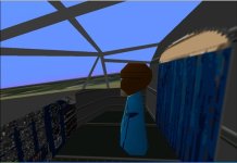
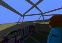
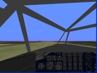
What I am more worried about, is whether I should use 1) a full panel with the right side as radio/navigator´s position, or 2) a full panel with duplicated instruments for the co-pilot, or 3), a 2/3, off-centre view panel, as would correspond to the Virtual Cockpit that I´m working on at the moment to add using SCASM. Here´s a couple of screenshots of that too. The VC panel bitmap is not yet the definitive one.

Cheers,
Aleatorylamp
 

Attachments

  • CondorVC1.jpg
    CondorVC1.jpg
    57.6 KB · Views: 0
  • CondorVC2.jpg
    CondorVC2.jpg
    59.1 KB · Views: 0
  • CondorVC3.jpg
    CondorVC3.jpg
    40.7 KB · Views: 0
Last edited:
Hello Aleatorylamp,

The Virtual Cockpit screenshots look good.
This is the kind of thing I was thinking about when I said that the Virtual Cockpit pieces do not need to appear anywhere else in the model and that other pieces of the model need not appear in the Virtual Cockpit.

Regarding Propeller Pitch:
Almost anything can be made to work with a pitch range of 15 - 65 degrees.
The question is whether or not you feel obligated to model the actual pitch range of the FW 200 propeller.
This is the same argument as with the 7 foot versus 9.7 foot propeller.
If you are just looking for performance and response, you use 7 feet as the diameter; If you are trying to use the actual numbers, you put in 9.7 feet and try to tune out all the resulting bad behaviour.

I can tell you that my Fokker E.III Eindecker has a "Whatever Works" kind of propeller.
I didn't know how to tune propellers at all back when it was released and didn't have the propeller pitch numbers anyway, so it got whatever propeller pitch worked.
By the way, that is not to say that I know what I am doing with propellers now. I just know a little more.

I am going to have to try out the two pitch and the controllable pitch propellers at some point.
Of course this will have to wait until I can figure out a few more things about constant speed propellers.

- Ivan.
 
Hello Ivan,
That´s what it´s like, isn´t it? One can do as much as one knows, and slowly one knows more...
We know what we know, and what we don´t, we try to imagine...

OK, I see your point on propeller pitch - it´s as good as the argument on the size.

I had kept on looking for some indication on the two pitch angles, finding quite a few pages on the Hamilton propellers, together with Harzell ones and others. Although in theory their engineers knew about constant velocity propellers, which they were striving for, it appears that technically it wasn´t possible to make one at first, so they came out with a simplified 2-position manually controlled one, with which they seem to have started revolutionizing the aircraft industry in 1930. Later they came out with a hidraulically, automatically controlled one, and then the CV one.

Strangely enough, I found not one single reference to the amplitude of neither the low take-off and climb angle, nor the high pitch angle for altitude, and there is no quote as to for what altitude either. This is rather logical though, as both would depend on the type of aircraft (speed) and engine horsepower, and all kinds of engine and aircraft sizes were catered for.

So I got an idea...
The logical conclusion was looking into what Mr. Beckwith (truthfully, what would we do without him?) would say about this in his test panel.


There, I had the feeling that a good take-off pitch would be between 17 and 19 degrees, as my Condor´s automatic futuristic CV prop has 15 set as minimum. Towards the end of the take-off run it´s at 18 and then it goes up to 25 for climb and higher speed low altitude flight.

Then with greater altitude, at speed, pitch progressively changes up to 28.7 at about 6000 ft and then goes down a bit to about 27.5 at the ceiling (19000 ft), and this gave me the feeling of a convenient setting of perhaps 27 degrees.

So, my two suggested settings would be 18 and 27 degrees.
This could perhaps be implemented using the manually controlled propeller option, and in the sim, using the manual pitch settings only at minimum and maximum, without the in-between positions. Low pitch would be valid upto 2000 or 3000 ft, and high pitch higher up, unless of course suddenly the pilot decided to slow down at altitude up to about 100 mph and then decide to do a power climb... there he would need low pitch for a while...

I also decided to snoop around in some Condors very nicely made for other simulators:
The FS2002 Condor, in the .air file, has min-pitch=18.5, and max-pitch=65. Then, in the Aircraft.cfg, beta min=9 and beta max=62. The FS2004 Condor has beta-min=1 and beta-max=60 in the Aircraft.cfg file. Not much help, except perhaps for the 18.5 degrees.

So I may not be very far out on my two 18 and 27 settings. I think I could try this out for a bit.

Thanks for your comments on the virtual cockpit - so I think it will work the way you say, adding the calls in the usual place for the VC, and putting the subroutines at the end of the listing.

Cheers,
Aleatorylamp
 
Manual Propeller Experiment

Hello Ivan,
I am trying out my 18-27 two-position "manual" propeller.
Record 500 Engine Piston Engine (FS98/CFS AI) is now:
Propeller Pitch Max Flat=27
Propeller Pitch Min Full=18

I don´t know what kind of effect these two have, but previously, there was 40 and 5 in here, and RPM was 25 RPM too low.
Now it´s at the correct 2050, but Hp is over by 7, at 727. However, getting Torque down to correct this has lowered RPM again, and now it´s at 2030, 5 more than my previous 2025 - a bit better. Nothing is perfect in this life!

In section 510 Propeller Parameters, I put in:
Prop Pitch Max=27
Prop Pitch Min=18
I then selected Option 3 (manual adjusment) for Propeller Type, and into the panel, I put the generic FSFS Conv 4-engine quadrant gauge, which includes propeller pitch adjustment.

I found that although the sim was now limited to 18 as minimum for take-off, it continues automatically selecting the best pitch availavble upto the maximum defined, unless the pitch lever is manually pulled down, which forces pitch to 27, reducing performance at low altitude, of course.
The question is, does Option 3 for manually adjusted propellers really work as would be expected?

In general, I suppose one could say that it is a bit more similar to the two-position manual propeller than it was before...
Now, S.L. performance is identical to what it was before, but at 6000 ft it´s 5 mph faster. I´ll see if I can adjust that.

Another strange effect is that RPM goes up with altitude. at 10000 ft it´s about 50 RPM over the desired 2050, and further up it goes down again, and it´s quite close to the correct 2050 again. Obviously, as it´s no longer a CV propeller, with Pitch being limited at 27, it makes the prop spin faster higher up, where previously pitch was 28.1.

All in all, I´d say it´s not too bad - it´s quite plausible.


Cheers,

Aleatorylamp
 
Last edited:
Hello Aleatorylamp,

It sounds to me like you just did pretty much what I did for the Eindecker:
You examined what the CFS flight model was doing when allowed a wide propeller pitch range and then set your pitch limits to what you had found from observation.
Who knows? Your guess MIGHT be correct. I certainly don't know that it isn't.
How does it do with Throttle and RPM set for Cruising?

By the way, I think I commented on this last time you had issues reaching full RPM with a project:
Use <Control>F4 to set engine for maximum RPM. That is what I was doing and I had no problems getting to 2050 RPM even with your older propeller.
I did not test it with the new propeller tables because I didn't want to reconfigure your panel and you had already removed the test gauges.

Regarding increase in power with the extra 25 RPM, I do remember telling you that you should use whatever gearing it takes to get full RPM for engine tuning.
Consider it a Bench Test of the Engine before it is installed. You should not be getting surprised by extra power.
Besides, 7 HP is pretty much nothing. It is well within normal production variation, and of course our mechanics are experts and always manage to get a few extra HP.

Your RPM variation sounds like your Record 512 Power Coefficient Table is still not quite as good a match as it could be for this propeller / engine combination.
It MAY be realistic though. Perhaps the real aeroplane behaved this way. The rather narrow pitch range is another indication that the Power Coefficients are not matching up all that well.
To do the comparison between your aeroplane's and the stock Record 512s, I did a check at ONE altitude:
Engine power was determined for 500 Feet altitude at full power and maximum RPM.
I also have run into similar problems in the past but have no solution which is why I am trying to generate my own propeller tables.
Lots of programming to do there!

- Ivan.
 
Hello Ivan,
I hope you are enjoying the Easter week!

Thank you for your interesting post, and your indications. I´ll go by them to continue - they are very useful, as always!
In general it seems to to be working, and as you say, the irregularities it could possibly also account for possible real irregularities coming from the simple 2-position manual propeller at the time.

I haven´t had time to do more than just test maximum power and performance at a few altitudes, and have to do the complete set of tests first, including behaviour during cruise, to see what the picture is, and take it from there.

I´ll do the bench test again, as you suggest, and also perhaps with the Beckwith gauge try to pin-point the pitch angle/s at which I get inconsistencies, do the angle-formula calculation and see if I can adjust the corresponding point/s on the pitch-angle graph to improve the power coefficient. Using AAM, the visual graphs are visible and have a little more meaning.

Good luck with your programming! That makes me think... A little QBasic programme to generate a text file containing the list of angles for this might even be possible for me to try out, and then import the .txt file into the AAM graphs. Matching all the spaces and decimals in the lines... That could be fun, but success with this is quite different from fun!

Thanks a lot again, and I´ll keep you posted!

Cheers,
Aleatorylamp
 
.....Days of the Condor

Hello Aleatorylamp,

Happy Easter to you also. I hadn't even thought that there was a holiday here.
My kids are on Spring Break.
My Son is sick again. He has had a fever for a couple days but not bad enough to give him medication yet.
For the last two days, my Wife and Daughter have been on a college visit.
They got back around 0700 this morning and are both asleep right now.
As you already know, earlier in the week, we were all on a couple college visits.
LOTS of things we need to do before this break ends, so I hadn't even considered that there was a holiday involved.

Regarding FW 200:
I would suggest that you first try to find out what the proper pitch values should be if not for that particular aeroplane, then for something very similar in power and speed.
Don't change things just because *I* said things don't quite look right. I have done no testing on your FW 200 that is really worth mentioning. Changing things without a clear objective is not terribly productive.
Did these people fit the optimal propeller to this aeroplane? If not, then perhaps it SHOULD be behaving exactly the way it is now.

Over the last couple days, I have also been playing with a Lockheed Model 10E Electra because it has an interesting instrument panel including the Sperry Autopilot gauge. Apparently there is some kind of configuration file that adjusts the behaviour of this gauge also. ....But again, without a clear objective in mind, it doesn't make sense to mess with it. Too many cans of worms open already.

My programming objectives for the Propeller Tables are pretty simple for now; I just want utilities that will help me work faster and be able to visually compare the curves I am trying to generate. The "intelligent part" isn't going to happen for a while yet.
Good Luck on the QBasic programming.

I actually was halfway tempted to do these utilities in Java to test out my development environment and perhaps show my Son who is trying to learn Java in school right now.
The problem here is that I can program about as fast as I can think in C but go quite a lot slower in Java.
Also, the problem is one of math conversions and binary editing and Java is not really the ideal language in my opinion.

- Ivan.
 
Hello Ivan,
I hope so much effort searching for a good college will bear the desired fruit, and that your son is recovering nicely!

Here, the holidays are being quite relaxing and good for a change, with some warmer weather and sunshine included. Today we had a healthy 2-hour walk through the forest in the mountains, and one daughter was at the beach with friends, and tomorrow there´s a barbecue at a friend´s vegetable patch in another forest in some other mountains, and the other daughter is going to the beach with some other friends! Then, on Sunday morning we´re all going to look for Easter-Eggs in the living room.

On Saturday I´ll probably get some more time for re-fine-tuning the Condor with the more realistic but less efficient propellers.
In order to get the objectives a bit clearer, at the moment I´m compiling a little comparison text document/chart showing the early Fw200 Condor versions and their engines and propellers, for comparison purposes.
I´m just adding some imperial measurements to the metric information on the chart, and I´ll try to post it tomorrow.

It might help to illustrate the difference between the first 720 Hp engined proptotyes with their 2-position, 2-bladed manual propellers, and the subsequent short pre-production run and their 800 Hp engines with 3-bladed CV props.
Maybe I can clarify some doubts derived from a lot of confusing, often generalized information.

[FONT=Verdana, Arial, Tahoma, Calibri, Geneva, sans-serif]QBasic sound interesting as it is notorious for its mathematical capacity, so I´ll see what I can do![/FONT]

Cheers,
Aleatorylamp
 
Hello Ivan,
So, as promised, for purposes of comparison and possible exercises of deduction and/or extrapolation, I´ve managed to put together a small compilation of the different engines that were used on early versions of the Fw200, as well as a table with the preformance of the early aircraft models.

I have also included the results of the .air file with the manual Type-3 propeller, this time including RPM, Pitch and Thrust readings.

The fact that this 2-bladed propeller only had 2 manually adjusted positions, would indicate that RPM varies with throttle position and altitude. The propeller had no constant velocity governor.

Thus, I would be inclined to think that the behaviour of the model would now then be quite acceptable with the new .air file.
I wonder if you would perhaps also think so.

Thank you in advance for your opinion, but if it were too cumbersome or complicated to look at all this information, please only do so if you have the time and the gumption! I don´t want this to be a bother.


Even though the engine is specified at 720 hp max. power at 2050 RPM, effective RPM during flight varies:
In the model, at S.L. under full throttle, and also at different cruise speeds for different altitudes, RPM is 2028 RPM.
Then, highest RPM is 2170, and occurs at full Manifold Pressure Altitude.
The specified 2050 RPM only occur at 2500 ft and 19000 ft.

Despite the propeller being defined as Type 3, Manually adjustable, it is not really possible to manually adjust it other than to force a higher value upto the maximum limit set in the .air file - in this case 27.

What cannot be done in the sim is to maintain a low pitch, in this case the minimum value of 18. The sim will always select the optimum from what is available in the pitch range. You can see how the Beckwith Gauge displays what the sim is doing with the pitch angle. It is only at 18 at very low speeds, and immediately moves upwards to around 25 on take-off and shortly after, and continues going up with altitude. You can force a higher pitch, but it what for? You only lose power, so it doesn´t really make sense.

Also attached is the new .air file and a panel.config file including the Beckwith Gauge if it were to be necessary.
Cheers,
Aleatorylamp
 
Last edited:
Hello Aleatorylamp,

We actually were out shopping most of the day and got back in the house only about two hours ago.
Hopefully I will have a chance to look at what you sent soon, but there are a few other tasks I am working on that I want to run for a while longer. I also need to help my Son in a couple programming assignments.

Regarding Propeller Pitch Ranges, Two-Pitch Propellers, and Constant Speed Propellers:
You say that you can get maximum speed and performance at about 27 - 28 Degrees, so why do you need coarser pitch?
Here is why and I have already asked about it a few times:
You get 720 HP at maximum boost and 2050 RPM.
You have given the boost pressure for Maximum Continuous, but what RPM is being used?

Consider what we know about Cars and their Engines. Airplanes have a lot of similarities.
In 1st Gear, I can get up to about 40 MPH.
2nd Gear can be run up to around 75 MPH or so.
3rd Gear goes well past 100 MPH.
This is at maximum acceleration.
Maximum Power is achieved at around 4400 RPM but fuel consumption is pretty high at this engine speed.
So what do we need more than three gears for?

....Because from a practical standpoint, much more time is spent under cruising conditions on the highway and
Not that much time is spent drag racing from a stoplight. (Take-Off and Climb)
On the highway in 5th Gear, I am typically running just a bit under 1500 RPM at 60 MPH and even with a big engine, fuel economy is not all that bad. (Cruise conditions)

With aeroplanes, there are a lot of similarities:
At Cruise we would have:
1. Low Throttle settings
2. Low RPM
3. Propeller in Coarse Pitch (High / Overdrive Gear)

....so it does help to have a higher gear / pitch setting even if it is only for cruise conditions.

- Ivan.
 
Hello Ivan,
The Easter Bunny has just hidden the chocolate eggs - without breaking anything this time - and even though we are all grown-ups here, in a while we´ll be hunting. My wife says it´s childish and wants to stop the family tradition, but meets with stalwart opposition every year!

Thank you for your reasoning!


So, if we were to imagine a 2-gear car, High Gear would obviously be for Cruise with Overdrive.
The problematic choice for Low Gear would be between midspeed-accelleration and get-away-from-stop-light accelleration.

Given that not all landing fields were very long at the time, although the plane was specifically designed for Tarmac, they apparently only used Low for Take-off. Hence, the two real pitch settings may well have been 15 and 28.7.

However, the sim won´t allow fixing any pitch anyway except maximum full coarse, so one may as well use the CV option!

I should really do the RPM-Pitch-Thrust test on the CV prop .air file, if only just to see exactly what happens.
Maybe I should also look at the fuel flow reading for both .air files...
...the more you get to know, the more you need to know.

Strangely enough, the engine delivers more Horsepower with the present 18-27 "manual" setting, that with the 15-65 CV one(even if it doesn´t really work as "manual"), or maybe it isn´t so strange...

Cheers, and a very Happy Easter to all!
Aleatorylamp
 
Hello Aleatorylamp,

Happy Easter.

Remember what I was telling you about how screwed up the Propeller Efficiency Tables are?
It sounds to me like you are getting an unintended interaction between the places in the Propeller Power Coefficient Table and Efficiency Table just like I was describing. If you look carefully, you can probably find a propeller pitch limit that will let you get onto the perpetual motion roller coaster.
That kind of silly behaviour is why I will get back to working programs for Propeller Table Generation when I get past this texturing exercise I am currently on.

- Ivan.
 
Hello Ivan,
How funny... Both funny "ha ha!", and also funny "strange".

Maybe they made the Propeller Efficiency Tables with a computer whose CPU had a faulty Mathematical co-processor.

I still can´t fully undestand all this - too many graphs on too many tables.
As soon as I try and relate the two to see the interaction I literally get a bit dizzy.

Anyway, I´ll decide what to do at some point. The manual prop setting does seem to be quite pointless though...

BTW, I tried a CV prop with Pitch range of 0 to 100, and I saw good accelleration at zero degrees pitch because the sim has a different calculation for low speeds. (As Beckwith explains,: "At speeds above the low speed theory limit, FS calculates thrust using propeller efficiency, engine power,and aircraft velocity..."). Then, I observed that at lift-off pitch was about 17, so maybe one should lower the minimum to 17...

Cheers,
Aleatorylamp
 
Last edited:
Hello Aleatorylamp,

I do not believe that the folks creating the flight models actually understood many of the capabilities designed into the system and that is why the flight models are as poor as they are.
I do not believe a Math Coprocessor was involved or even necessary for this kind of work.
My own calculation thus far are quite simple but then again I am not anywhere near finished yet.

My own belief is that the two pitch propeller is a workable possibility but I can't give you any useful advice at the moment because I have not experimented there yet. The constant speed propeller appears to be the more difficult but also more generally useful problem and I am working on that part first.
I have a few guesses on how to do the two pitch propeller which involve creating a very strange looking Propeller Power Coefficient table, but do not yet have the programs even to do the constant speed version yet. Basically it will look a lot like a horribly mangled constant speed Power Coefficient Table....

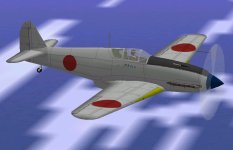
My technicians will be working on adjusting the spray guns at the moment to see what works best for doing a camouflage pattern for the Ki 61 Hien (which also is the main propeller test aeroplane).
See the attached screenshot for the un camouflaged aeroplane.

- Ivan.
 

Attachments

  • Ki61-Id.jpg
    Ki61-Id.jpg
    218.6 KB · Views: 0
Hello Ivan,
Once again, a nice, admirably clean build, your Ki 61 Hien. Looks like quite a powerhouse, with nice lines.

As I read your coment on the feasibility of a 2-position propeller, it occurred to me how to make a 2-position propeller:
Once the 2 pitch angles needed were decided, shall we say, for example 15 for low and 30 for high, one would simply copy the 15 degree pitch graph to the 20 and 25 degree one , and then copy the 30 degree graph to all the rest, that way you would get a 2-position 15-30 propeller.
Given the inability of CFS to allow completely manually controlled pitch, low pitch would be controlled automatically, but high pitch could be used manually at any time, even by mistake!
Then, of course it became clear that one would have to be able to block the sim´s ability to interpolate all the time, which is what it´s going to do unless set for maximum pitch. If there´s no way to stop this, my idea of course won´t work.

Cheers,
Aleatorylamp
 
Hello Aleatorylamp,

Actually the Ki-61-I was a bit on the underpowered side. It was probably comparable in power to the Messerschmitt 109E but with a bit less climb performance because of the extra weight. In speed and ceiling it was closer to the 109F but the handling was superior overall.
This project has been hanging around about as long as the Mitchell. I decided to build it because of its nice clean lines and appearance and also because there wasn't a good one that existed for CFS.
I want it finished so that it can be transformed into the Ki 61-II which never had much luck and the following Ki-100 which was a fairly impressive fighter.

Your idea of combining the graphs is pretty much what I was thinking but the problem is in determining where that graph should be by determining the power coefficient from your engine / propeller. The problem becomes even more complicated when one considers that it must also behave properly at different altitudes.

Just taking a break from Weekend Chores.

Gotta Run.

- Ivan.
 
Back
Top