Focke Wulf Fw200-A Condor

Hello Ivan,
Your plan for the Ki-61-I sounds very good, and will make a nice trio-collection with the -II and -100 to follow.

The performance results of the "manual" propeller test for the Condor were very similar to those done with the CV propeller, but after your car gear-box comparison and the comment on coarse angles being more efficient for cruising, I am thinking of increasing high pitch, which is now at 27.

The CV prop tests showed that at 6000-7000 ft, 39.2 degree pitch was being used, and then higher up, from 12500 to 19000 ft, pitch went from 38.5 to 37.5, so I think I´ll try something like 35 degrees now.

Low pitch at 18 seems fine as accelleration is very adequate for take-off and initial climb, so I can leave that alone.

I´m still trying to figure out what I could do to the Power Coefficient Table, and where, to improve something, although for that, I´d have to be able to understand the relationship between the Propeller Efficiency table and the Power or Thrust Coefficient table a bit better. Then, I´d also have to see where performance needs improving.

The Propeller Efficiency table establishes the efficiency of the propeller at each pitch angle setting, and depends on how good the propeller manufacturer made the propeller - i.e. how well the propeller provides thrust to push back air at all possible aircraft speeds and altitudes after the correct pitch angle is chosen.

Then, the explanation for the Power Coefficent Table is the power that the engine needs to turn the propeller. So... that would depend on how well the engine can manage at different RPM... and RPM depend on pitch angle, aircraft speed and air density.

The reason for the existence of two propeller tables instead of only one, still escapes my understanding - but of course there must be a good reason, otherwise there would only be one table.

Cheers,
Aleatorylamp
 
Hello Aleatorylamp,

I finished programming a few utilities over the last couple days that will make it easier for me to experiment with propeller tables.
There are only another 4-5 programs I still need to do.
Tonight I have been helping my Son on some Java programming, so have not gotten much done.

I played with AAM V2.2 last night. It appears to be quite a neat little utility for minor propeller tuning which is good because neither AirEd nor FDE can do anything there.

I can't give you any more insight into what the proper behaviour or response of the propeller / engine of the FW 200 really should be, so I won't be commenting on the subject.

The texturing exercise with the Ki 61 got pretty much nowhere, so there is still plenty to do there.
When I finally do get some results, I will post them on its own thread.

- Ivan.
 
Hello Ivan,
Well, good luck with the utilities then!
I also like the way AAM shows tables 511 and 512 graphically, and lets you manage the graph points. It also allows changing the vertical axis to show the J factor instead of the pitch angle.

I keep re-reading the Power Coefficient Section in your descriptive document on propellers, and also Mr. Beckwith´s .pdf on propellers. I understood the bit on Propeller Efficiency, and also Mr. Beckwith´s formula for this Table. Then, I also decyphered his "exercise" for the reader, i.e. the Formula for the Power Coefficient. What is confusing his description of how the Sim Algorithm uses the tables to finally calculate thrust. It appears that both Tables are looked up simultaneously.

My question was only rhetoric, why both graphs were not combined into one, which I suppose is either impossible or too simplistic. Anyway, I won´t pursue the point any longer.

I´ll be on the lookout for the new Ki-61 textures then!
Cheers,
Aleatorylamp
 
Hello Aleatorylamp,

So far, I have finished (nothing is ever REALLY finished) three programs.
None of them are smart; They just enable me to process data faster.
The fourth program should have been easy (and still might be) but did not work as intended.
I have not tried to figure out where it is broken yet. It isn't really necessary though. None of the programs are really essential.
The problem is that when you are working with binary files, debugging becomes a bit more difficult.

I also found out a couple other things:
1. My programming speed is much slower now. I know what to do, but have to look up parameters and include files more often.
2. The keyboard on my laptop is good but not nearly as good as the ones on my earlier desktop machines. I can't type as fast.
3. I had a really difficult time with trying to get an exponent formula to work in C. I had forgotten that a lot of stuff isn't really implemented in C and needs library calls at which point it becomes about as easy to program your own version.

Regarding Propeller Tables:
(This really would be so much easier in person. Typing is much slower than talking.)

An Engine can generate a certain amount of Torque at a certain Rotational Velocity. (5252 is a really cool number.)

A Propeller of a given diameter, blade form and blade pitch angle has a resistance to being turned.
For the moment, let us forget that we can change the blade angle at all.
Let us also forget that the Propeller has mass or moment of inertia because they are not part of THIS calculation.

So how can we calculate the resistance to being turned?
We know the resistance increases as we try to spin it faster, thus RPM (or rather Revolutions per SECOND) must be part of the calculation.
Because of the blade angle, the resistance to turning is highest at zero forward speed.
(Actually it would be higher in reverse air flow.)
As we start moving (increasing Advance Ratio or J), the Propeller becomes easier to turn as the Angle of Attack of the Blade becomes closer to the combined airflow of rotation and forward motion.
(Thus, the Power Coefficient or resistance to turning drops as J increases..... Up to a point.)
At some point, the Propeller Blade is going directly Edge-On to its relative air flow.
At this point, there is ZERO resistance to the propeller turning. This is where the Power Coefficient drops to ZERO.
If we go even faster (higher Advance Ratio J), the Airflow starts driving the Propeller. This is where Power Coefficient is Negative.

Now that we have a calculation for how much resistance there is to turning the Propeller at any Air Speed, what can we do with it?

We go back to the Engine and see the amount of Turning Force (Torque) it has at the particular RPM we are encountering.
Is the Engine Torque greater than what we need to drive the Propeller? If so, the Propeller Speed increases.
Is the Engine Torque less than what we need to drive the Propeller? If so, the Propeller Speed decreases.

With a Constant Speed Propeller, the Governor is watching this RPM fluctuation.
If the Propeller is slowing, the Blade Pitch is decreased until the Engine Torque matches the Torque required by the Propeller.
If the Rotational Speed is increasing, the Blade Pitch is increased until the Engine Torque matches the Torque required by the Propeller.

The Governor is only interested in maintaining the Engine RPM requested and this is how it knows how to do it.
It only does a comparison between Engine Power (Torque * RPM) output and Propeller Power required and acts accordingly.

So far, this discussion is only related to Engine / Propeller Power Coefficients as calculated from Engine Horsepower / RPM and Table 512 values. This discussion has ABSOLUTELY NOTHING to do with Table 511 for Propeller Efficiency.

Table 512 describes how the "Propeller" reacts to being turned. The form of the curves are basically a functional description of Propeller resistance. The curves would change a bit if the "Propeller" were just a couple Wooden Sticks, but the concept would be the same. Note though that if the "Blades" were just round wooden sticks, then the power required would not change if the pitch angle changed!

Note also that thus far in all the formulae for Propeller Power Coefficient, there has been no mention of the number of Propeller Blades or their width (Activity Factor). The lack of these details in the formulae is why we need to adjust the Propeller Power Coefficient Table to match the one in a particular aeroplane.

Hope this makes things more clear.

- Ivan.
 
Hello Ivan,
I´m glad about your progress with the utility programs, and I´m sorry to be causing you so much inconvenience and trouble with the explanations you are so kindly providing. I think that with your last one just now, I have finally managed to grasp the relationship between the two tables, and why there have to be two and can´t be unified into one.

The inconvenience of typing instead of speaking is made quite a lot worse when preparing a post here on the thread. Not because it times-out quite soon - one already expects that, but because there is some obnoxious, unnerving accidental key-stroke combination that throws you out of the text editor into some other page, and of course you lose whatever you have been typing.

This trap involves some mistaken keystroke in the lower left keyboard corner.
I have the feeling it is the left CTRL key accidentally hit by the little finger plus some other key.
After losing a longish text twice running one tends to give up.
Does anyone know how to switch the stupid combination of left CTRL + other key off ???
It doesn´t happen on the Notepad...

Anyway, back to our Propeller Tables theme:
I was already quite clear on the Prop Efficiency table giving the ability of the prop to push air backwards, depending on pitch angle, RPM, Aircraft Speed and Air Density. The way the air flows, and what pitch angles do, is also clear - when the propeller acts like a kid´s paper windmill or when it blows like a fan.

I also understood the general concept of the Coefficient Table representing the power required by the prop to turn and push air backwards - again for each pitch angle, RPM, Aircraft Speed and Air Density.

My problem was to see the connection and interaction between the two. It should have been quite obvious, but it wasn´t, and I couldn´t understand why they couldn´t be in a same single table, as both concepts depended on and acted on the same things: Pitch, RPM, Speed and Altitude... so I´m afraid the separate ideas for a propeller´s required power and provided power was not that clear yet.

That´s why I couldn´t understand that it is possible to act on a certain point in one of the Coefficient graphs to provide more power to the propeller, the same way as we acted on a point in one of the Hurricane´s Efficiency graph to provide more (or less) thrust for maximum speed at S.L.

So, there seem to be not only too many parameters for one table, but the two concepts are to be kept separated, so that the sim can compare the two tables and find the point where power required matches power provided at all moments, all depending on the same set of conditions. That point is then used to calculate thrust... OK!

Anyway...
After my last post this morning, I decided to continue my experiments with my 2-position, manually adjusted prop, making 2-graphs out of the 11 graphs in the table. I not only inflicted this on the Prop Efficiency table, but also on the Prop Coefficient table.

You had commented on the problem of where to place the separation between low and high pitch, and I remembered a Fw200-A pilot´s comment that low pitch was for take-off, and very soon after, the second position had to be set with the pitch levers. Unfortunately there was no further comment. Whether this included initial climb or not, is unclear. I have the feeling it has to be done during initial climb, once a certain speed has been achieved. That´s why I went for the 25 degree pitch point initially.

Well, to keep a satisfactory take-off ability, low pitch at 18 seems to be a OK for a start. High pitch at 25 as we have seen, is too low for efficient cruising, so I decided to try 32, but maintaining the point of division at 25, and take it from there.

Initially I turned the graphs for 15, 20 and 25 degrees into a graph for 18 degrees, interpolating between the graphs for 15 and 20. Then, I turned all restly graphs from 30 to 65 into a graph for 32,5 degrees, interpolating half-way between the graphs for 30 and 35. The division point was between 25 and 30.

Test results were all-round quite low, a lot under what I was expecting, so I decided to include graph corresponding to the 30-degree into the low pitch group. This way the division is now between 30 and 35. Performance improved all round, and was generally about 7 mph low at altitude and a bit more at S.L.

My next decision was to raise the high pitch group from 32.5 to 35 degrees, keeping the division between the 30 and 35 degree graphs. Performance at altitude improved and there I was now only 5 mph low, but S.L. performance (expectedly) got a little worse.

Updated paragraph: Then, using the last 18-35 degree set of graphs, I improved S.L. Speed with the Efficiency table by increasing the J values 0.8 to 1.2 a little, and the difference is now more similar to the difference I´m getting higher up. The next step will be to lower Airframe Drag to get correct S.L. performance. After seeing what happens higher up, I´ll adjust higher J values.

Thinking about it now, perhaps it wasn´t necessary to copy all the graphs into the corresponding 2 positions - it should be enough just to specify maximum and minimum pitch in the FS98 Engine and Propeller Parameter records, which I also did, but as I didn´t trust the sim, I manipulated ALL the graphs!

So! I´ll keep you posted!
Thank you very much for your concern and for your time, and I´m very sorry this has been a bit cumbersome for you.

P.S. With AAM, be careful when increasing the height of the graph window´s top margin to get a better size to edit the graphs.
If you go too far, it won´t close again and you´ll have to re-install AAM! You have to leave about half a line of text at the top to prevent it from blocking.

Cheers,
Aleatorylamp
 
Last edited:
Hello Aleatorylamp,

I get the impression from your response that you still do not really understand the relationship between the two graphs.
Here is why I came to this conclusion:

You describe a "Windmill" effect as a result of the curves in the Propeller Efficiency (511) Table.
That is not where this effect is created.
Look again at the Power Coefficient (512) Table.
Pick a Propeller Pitch Angle (25 Degrees does pretty well since it is within your operational range for the FW 200).
The X Axis is the speed of the aeroplane expressed as Advance Ratio. (True for a given RPM. Not True if your RPM changes.)
The Y Axis is the amount of power required.
If it is positive, it is the amount of power needed to turn the Propeller to drive it through the airstream.
If it is negative, it is the force exerted by the airstream in TURNING THE PROPELLER. THIS is the Windmilling Effect you were looking for.

Regarding the Propeller Efficiency (511) Table we have neglected thus far.....
Look at it this way:
Propellers in our flight simulators DO NOT push Air Backwards.
Their effect also does not depend on Air Density (!).... (I am pretty sure about that.)
So what do Propellers actually do in this GAME?
They convert Engine Power into Thrust. (Yeah, right.... Simple meaningless answer, right?)
Table 511 does this by using an Efficiency Multiplier to reduce the Power that is to be converted to Thrust.

An Example to Illustrate:
Let's say our Engine provides 1000 HP at our particular altitude.
We do our Lookup for our current flight conditions (Air Speed, RPM, Blade Pitch) and find that the Efficiency is 80%.
That means we only have 800 HP working to propel the aeroplane.
Since 1 HP = 550 Foot-Pounds / Second, we are getting 440,000 Foot-Pounds / Second of POWER.
Since Power == Force * Velocity, we need to figure out how fast we are going.
Let's say we are going 200 MPH.
That would be 293 Feet / Second.
If we take 440,000 Foot - Pounds / Second and divide by 293 Feet / Second, we get 1502 Pounds.

Thus under these conditions, we are getting 1502 Pounds of Thrust.

So why do I recommend tuning the Propeller Efficiency Table for minor adjustments?
If nothing else changes (Which is never True but hopefully it doesn't change much),
if we drop the Efficiency Entry from 0.800 to 0.750, the Thrust drops to 1408 Pounds with minimal effects elsewhere.

Actually it DOES affect other things:
Now that there is less Thrust, the velocity will be lower which slightly changes the Advance Ratio and most likely also increases the Thrust above the 1408 Pounds that we calculated, but the net effect is that we end up going a bit slower.....

In general this method works pretty well, but this model does have a few things it does not represent all that well.
If we ever meet or if life slows down a bit, we can go there, but it is a bit beyond the basics.

- Ivan.


P.S.
All this is really cool under normal flight conditions but what about when we run up the Engines at the START of our Take-Off Run?
Well, you take 440,000 and Divide by Zero Forward Speed..... And the Whole World blows up because you now have infinite Thrust!
That is why a different method (Low Speed Theory) is used at low speeds: this model doesn't work well there.
 
Hello Ivan,
Thank you very much for your post, your pacience, and your efforts in preparing it!

I did or do understand a little more than you think, and when I mentioned the Windmill effect as opposed to the blowing fan, I was not referring to the propeller efficiency table 511, but to your to your comment "If we go even faster (higher Advance Ratio J), the Airflow starts driving the Propeller. This is where Power Coefficient is Negative."

... so I know that´s why we have to increase the pitch angle so that we can bite the air again ...and start getting laminar flow on the surface of the blade, which happens between 15 and 25 degrees angle of incidence on the blade surface, 19-20 degrees being the optimum, where apparently about 60% thrust comes from the suction on the convex surface and 40% thrust comes from the pressure on the concave one.

My reference to air being pushed backwards to move the aircraft forwards is based on Newton´s Law - any Action causes a Reaction, but OK, in the sim there´s no air and the only things that push air in a computer are cooling fans. The virtual propeller is all mathematics of course. I just needed a physical example to understand and express things.

My reference to Pitch angle, RPM, Airspeed and Air Density (altitude), was intended as illustrative of the factors that inluence what the sim perhaps does to its prop, and what its prop does to aircraft movement. If any factor changes, it affects some of the others. ...without mentioning power or thrust here, the following being for real planes with NO CV props, and just to understand:
- reducing Air Density (increasing altitude, thinner air, less resistance) will make RPM go up unless Pitch is coarser to compensate.
- increasing Airspeed will make RPM go up and will require coarser Pitch, and RPM will go down again
- increasing RPM will cause Airspeed to increase with the correct pitch angle unless there is blade stall.
- increasing Pitch Angle will change RPM and Airspeed depending on whether Pitch Angle is convenient or not.

The CV governor (if present) will try to maintain constant RPM, adapting Pitch Angle so that the blade angle of incidence to the air flow is best possible at all times. If there isn´t one, the pilot has to adjust the pitch lever, if there is one. If there isn´t, we make do with the fixed propeller we have, and fly within ranges of speeds, RPM and altitudes it is limited to.

Update: OK, I studied the details in your last post, on the benefits in adjusting Efficiency rather than Power Coefficient and the resulting effects. Also, how the 1000 Hp engine gives 800 Hp at 80% Efficiency at a certain moment.
It is all rather complicated, but with experimentation some things are possibly becoming a bit clearer as well.

Instead of reducing Airframe Drag as I´d planned (to improve overall performance by 5-10 mph), I´d thought of lowering the Propeller Coefficient graphs by one or two pixels instead, to see what happens. This should, if I understand correctly, make the propeller require less power, and so produce slightly more thrust. Update: It didn´t work, and seemed to lower thrust a lot and mess everything up, so I´m going to l leave the Coefficient Table alone for the moment!

The propeller, not being a CV one anymore, does increase RPM a little with altitude. At S.L. it´s a bit below spec, goes a bit above spec higher up, and goes down again to correct spec RPM at the ceiling.

I also understand the low-speed model being used for take-off. It looks like it is used until the moment where the minimum pitch reading starts increasing. With a 0-65 Degree pitch CV propeller, you can see pitch at Zero for this time.

Incidentally, after take-off and during initial climb, there is a moment where the Beckwith gauge visibly starts juggling numbers - it is probably going from low pitch into high pitch.

Thank you very much again. I do appreciate your help and I hope not to be exasperating you too much!
Cheers,
Aleatorylamp
 
Last edited:
Hello Aleatorylamp,

I am glad you understand the way things work.
I still have my doubts from what you just posted, but then again, I have lots of doubts that I understand things myself and I am writing as if I am THE authority on the subject which is certainly not the case.

Part of the issue is to not only have an understanding of the physics of what is happening but also to understand the mathematical model and its shortcomings. The mathematical model is mostly what I was trying to discuss here because that is the part we need to tune to get things to work correctly.
A lot of times, flight modelling is also a matter of creating the effect you want even if you have to use features that are not intended for the purpose.

I had a bit of a programming issue last night.
My Decode utility had no trouble converting Record 511 into a text format to import into a spreadsheet (I still have not tried to do the import yet), and the Encode utility had no trouble converting the text file back into the binary AIR File format.
The comparison of the original AIR File and the one resulting from the convert to text and convert back to binary showed no differences.

Last night before dinner, I finally tried it out on Record 512. The conversion to text worked and the conversion back worked also, but the resulting files were different!
If I converted the new AIR File to text, I would get the same result as converting the original AIR File to text....

After a couple hours of messing around, I finally figured out what the real problem was:
These Tables all use a Double Precision Floating Point format for every number other than the Data Length, Rows, and Columns.
I obviously had to know that to do the conversion properly to text.
I was converting to #.##### format (5 decimal places).

What I found was that in some places though not all, the actual number was using 10 significant digits (9 decimal places).
Addressing that issue with a code change only took a few minutes as soon as I figured out that the default C / C ++ format string for Floating Point only displayed 6 decimal places.

While it is possible to store a number with more than 10 decimal places, for now I will accept that limitation for space reasons.
I can easily change it with a change of one #define if I decide I need to.
From a practical standpoint, even 5 decimal places was good enough but allowing for 10 in the code is just an acknowledgement that these numbers really are Double Precision.

So now I have 3 programs working and one that still has a bug I haven't found yet.

- Ivan.
 
Hello Ivan,
How interesting! Text format for the numbers to create the table was the was the first thing I thought about, but haven´t got round to doing anything yet. In Qbasic it involves Opening and Closing files onto the disk, to be able to use them.

The following, you may find useful: There is a way around the binary files - AAM Exports and Imports Text file tables.
I tried the AAM Export Table option, which produces a Text file with numbers that have 15 decimals!

If you create another file with the same number of columns and lines and spaces, you can also import a table into AAM. That might make your life easier.

The first line is about the number of columns and lines, then come the J Factors, I think, and then all the numbers.

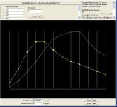
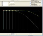
Here are some screenshots: One of all those numbers in list of the exported Table, and 2 of the the 2 lonely graphs on my new 2-position manual propeller´s Prop Efficiency and Coefficient Tables! Very sparse-looking...

I understand that the Sim uses numbers and mathematical ways to emmulate aircraft behaviour, and I realize that the point you are making because we are working with the sim to achieve aircraft behaviour as correctly as possible.

There is still a problem with the RPM, which are on the low again, at 2016 instead of 2050 as per spec.
Strange, as I´m not using a CV propeller, so I´d expected that to vary somewhat, below and above the spec number, as it was doing, but that has stopped! RPM are not going over the top as they were before. As you say, obviously this is a mathematical phenomenon because it is not a real propeller in real air...
I ´ll see if I can apply the tricks you showed me for the Zeppelin to get the RPM up a bit and keep Hp the same.


Anyway, after adjusting Airframe Drag slightly and tweaking Torque, with my 2-position propeller experiment I have Maximum Power and Speeds almost exactly where I wanted them, for the moment as the three altitudes I´ve tested:

- At S.L.: 226.8 mph with 720 Hp (33.6 pitch and 949 thrust)
- 8500 ft: 246.6 mph (1.6 mph too fast) with 690 Hp (34.2 pitch and 870 Thrust)
- 12500 ft: 244.5 mph with 584 Hp (34.1 Pitch and 739 Thrust)

Now I have to see about Cruising and the Ceiling, but later, because I have to rush.
Cheers,
Aleatorylamp
 

Attachments

  • Condor Table 511.jpg
    Condor Table 511.jpg
    47.8 KB · Views: 0
  • Condor Table 512.jpg
    Condor Table 512.jpg
    44.7 KB · Views: 1
Last edited:
Hello Aleatorylamp,

The Decode and Encode programs are done. I currently have the maximum precision set at 10 decimal places but can change that to 15 (The limit of accuracy for Double Precision) and recompile in about 30 seconds or so which includes the compile time.
Those programs really were not difficult to write and adjusting them is pretty easy.

For the Decode, the program first tries to convert to 5 decimal places and compares the result to the original number.
If it is the same, it is printed into the text file. If it is different, it next tries 10 decimal places (which I will be changing to 15 decimal places shortly).

The Encode program doesn't care how many places as long as the numbers are separated by a space, tab, or comma.

I find your first screenshot VERY odd because almost all the floating point that is being displayed consist of non-zero digits all the way out to the last decimal place. I should go back and see what the stock AIR Files look like there.
I need a few more experimental test subjects anyway.

- Ivan.
 
Hello Aleatorylamp,

I almost forgot to comment on the Graphs that you have as attachments.
Regarding your Table 511 Propeller Efficiency:
For a Blade Pitch of 25 Degrees, it would reach a Zero degree Angle of Attack at Advance Ratio = 1.1.
I figure for my calculations that it can create thrust even at about -5 Degrees AoA because of the cambered blade and because the single angle is an approximation for most of the blade, so that would mean that by J = 1.4, it should have Zero efficiency.

From what I can see from your Table 512 Propeller Power Coefficient:
It appears to be Zero (I assume that is the horizontal line I am seeing) at J = 0.8 and negative beyond that.

What this means (if I am correct in reading your graphs) is that beyond J = 0.8, you have this wonderful magical thing going where the airstream is driving your Propeller and your Windmilling Propeller is generating Thrust at the same time!
If this is the case, this is the perfect example of the Perpetual Motion I am trying to avoid.

- Ivan.
 
Hello Ivan!
:biggrin-new: What a wonderful world!... Maybe I should leave it like that on purpose!! :devilish:

Thank you very much indeed for your views. I wasn´t expecting an informative answer, so all the better! I didn´t expect that it was so easy to tell much just by looking at the graph pictures, but on second thoughts, it is obviously so!

Now, what is quite a different matter for me, is to understand what you are saying... and another matter altogether, to know what to do about it. I´ll think about it, looik at the graphs and see if I can tell what´s happening and what to do about it.

In principle, the fact that all the graphs are now only 2 instead of 11, should make it easier.
What is also happening, contrary to what I was fearing, is that given the presence of only 2 graphs in the whole table, even though the sim tries to interpolate, it always gets the same information, so effectively, it really only has 2 pitches, right?

Then, I am not quite clear about whether the effectivity of the manual operation under Propeller Type Option 3 (manual) is effective or not, as long as the sim is allowed only to use the 2 pitches given.

Moreover, it doesn´t really matter if the computer automatically selects low or high pitch instead of the pilot doing so, if the set-up works, of course!

...I would like to get rid of the perpetumobile thingy though... let´s see if I can manage to understand this.
Thanks again! :encouragement:

Re. The AAM Exported Tables in text format. Maybe it´s a good idea to export and look at the default P51d Tables, but right now I have to rush again. The family is demanding to be fed... and then I have other stuff to do...
Cheers,
Aleatorylamp
 
Hello Aleatorylamp,

I wish the Quote feature was working here. It would make things so much simpler.

Regarding leaving the Perpetual Motion: I believe every stock AIR File has this weirdness and I have never seen anyone but me comment on it.
It bothers me so much that I thought it was worthwhile to learn to build my own Propeller Tables.
It isn't the only reason, but it is one of the factors driving the development I am doing.
Part of the reason is also that I like to understand how things work and this is a way to test my understanding and get some of the effects I want to implement. There is still plenty to learn in a 20 year old game.
Note though that none of my completed projects thus far have addressed this issue at all.
(Then again, we all know projects are never "completed"; There is always room for improvement.)
This is an interesting pattern though, a lot of the things I am working on end up in your projects.
Note that your Great War Giants have a fair amount of propeller tuning and to this point, none of my released projects do yet.
None of my own projects has a custom gauge yet but your Heinkel 162 does!
Hmmm.....

I already pulled all the stock AIR files onto my laptop to look at the propeller tables, but last night, I was doing some debugging on another program and didn't get to extract any of the tables and look at them, but now I know the extraction program works.
The bug was a very cute one that was pretty obvious once I brought up the before and after files in a hex editor to do a comparison.
Turns out the problem was not in the code section that I rewrote a couple times but in the file open sequence.....

Regarding two pitch angles in your graphs instead of 11:
I don't believe it will make a difference.
Note that the stock graphs have even multiples of 5 for pitch, but the actual angles you encounter are interpolated between them.
Note also that when you changed the pitch angle from 0 to 100, the graph was not a limitation.
I don't know anything else about Manual Pitch Propellers, so can't give any advice here. I have not experimented with them yet.

- Ivan.
 
Hello Ivan,
True, the way some of your experimentation end up in my uploaded aircraft is quite curious - it´s actually quite fantastic for me, as I can benefit from it - plus the fact that it makes things all that more interesting!

The reasons that you express for doing what you do are in reality the only real reasons for doing things anyway!
Moreover, despite this being an almost 20 year old game, the fact that the .air file is directly accessible without having to go through an aircraft.config file as in more recent simulators, seems to me to allow more influence on aircraft behaviour and is an added attraction.

It is also curious that the Perpetual Motion effect has not been commented on before.
I´m still trying to decypher what it´s all about. I just got home and will investigate in a moment - let´s see what I can discover.

OK for confirming the non-necessity of turning ALL graphs into only two (so one CAN trust the Sim to use only between 18 and 35). I had really already expected that, so just ignoring anything above 35 will do. For the 18 one, I´ll then use the 15 and 20 ones.

Cheers,
Aleatorylamp
 
Hello Smilo,

The Quote is still not working from here.


Hello Aleatorylamp,

I just extracted Record 511 and 512 from the stock Hurricane Mk.I AIR File and got pretty much what I expected.
Notice how most of the values end in zeros in comparison to your screenshot in which they do not?
This is definitely odd.

- Ivan.
 

Attachments

  • Hurricane_I_511.jpg
    Hurricane_I_511.jpg
    58.3 KB · Views: 2
  • Hurricane_I_512.jpg
    Hurricane_I_512.jpg
    50.8 KB · Views: 0
Hello Ivan,
I hadn´t exported any of the stock AC propeller tables yet, so I looked at a few points on the P51d graph lines just now, and they don´t have so many decimals at all! - two or three mostly, and the zeros don´show in the little AAM number window.

The Condor´s 511 Table I exported as a text file and posted a screenshot of, was the "two-graph" table I had made.
Typing the values from one graph to the other using the little number-window would have been endless, so I did it by moving the mouse, keeping the right mouse-button pressed, to adjust each point along each graph lline.

Much faster to do, but very slightly inaccurate. Visually the 2 graphs seem one line each, but in reality there are minor inaccuracies, which is the reason for the 15 non-zero digits in the decimal places!


I´m sorry if this has been confusing...

Cheers,
Aleatorylamp.
 
interesting, it seems to work for me.
but, then again, i guess i'm special.

Hello Smilo, how´s things? I´m quite sure you are, indeed!!

This is just to test the quote feature - which I never use...

Once I get done with the Condor, ...and the Schnellbomber... then we can resume Ad2k!
Cheers,
Aleatorylamp
 
Negative pitch

Hello Ivan,
From what I can understand, in normal or logical conditioins, negative pitch areas in each pitch graph in the Coefficiency table would be chosen by the Sim when aircraft speed is greater than the corresponding speed for the pitch needed by the power calculation, i.e. diving without pushing the throttle, or pulling back the throttle at high speed. Negative pitch then acts as a brake, and of course windmills the propeller.
For aircraft where reverse pitch could be used for reversing on the tarmac or braking in flight, like some turboprops can do, (this is not possible to do in CFS1 propeller .air files, I gather), the negative pitch would exert a reverse thrust.

My two graphs in the Thrust Coefficiency table are simply the unaltered 35 degree pitch graph for high pitch (covering pitch graphs from 35 to 65 degrees), and a low pitch graph which I interpolated using the 15 and 20 degree graphs, to try and adjust it for an in-between position corresponding to 18 degrees. This is the graph for pitch graphs 15-25.
(OK, pitch above 35 will not be read by the sim as it´s limited in the max. pitch parameter).

The graphs I tweaked a little to adjust speeds for J=8 to J=1.2 were the Propeller Efficiency ones to get S.L. maximum to 227 mph and speed higher up around 245 mph.

You mention that there is a point on the Thrust Coefficient Table where negative pitch drives the propeller and produces thrust - i.e. the perpetumobile effect. I´m afraid I don´t know enough to be able to discover where n the graphs the sim would choose a negative pitch point, so I can´t try out any changes, so I must confess I´m rather lost here. Consequently, I don´t know how to correct this.

Cheers,
Aleatorylamp
 
The Quote is still not working from here.

- Ivan.

i'm sorry to say,
i have no idea why
reply with quote is not working for you.

i guess there's always the old
copy/paste and wrap it in quotes method.
you could even change the color
and make it bold and/or make it italic.
for example;

"The Quote is still not working from here."

sorry, that's the best i can do.
 
Back
Top