• Guest Please check out the Help Wanted thread in Ickie's NewsHawks.
    The future of the Outhouse depends on you!
    Help Wanted

Gmax combining spline shapes

WesCov

Members +
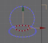
Still following along in the tutorial. I have much more complicated cross-sections than just circles. I could combine circles, ellipses, and rounded corner rectangles to create a starting shape (convert to mesh and attach). How do I remove all the intersecting vertices so I just have the outline? In the intersection of the example below, if I delete the selected vertices parts of the borders disappear.

Is there an online manual? Or other tutorials? I really do try to do research for answers before posting.
 

Attachments

  • Combining splines.jpg
    Combining splines.jpg
    7.7 KB · Views: 29
I don't know about g-max but you join the parts, delete the polys and build new polys using three points. You usually have to "hide" polys so you can get at and isolate the three you're selecting. As far as deleting the vertices select and delete.
 
In gmax I've attached to shapes together and selected the inner vertices. If the shapes are mesh then some of the border disappears when I delete the inner points, and if the shapes are polys, the entire border disappears. I essentially want to overlap a bunch of splines and end up with only the outer border of the combined shapes. The point is to trace the cross-sections -- is it better to use line or arc and join them together?
 
If you are dealing with arcs and splines in the same plane you need to slice both lines at the intersection points to create common vertices and then 'weld' the common vertices to create a single point on each side where the lines/arcs intersect. This will make a single spine with the required cross-section which you can then extrude to create the mesh you require.

In GMAX you can specify how close vertices have to be before they will 'weld' together so that you can select a bunch of vertices by dragging over them and only the vertices within the specified distance will weld to each other. I always used to use 0.010" (ten thousandths of an inch) as my weld distance so that if two (or more) points were within that distance of each other they would become a single entity when the 'weld' command was applied.
 
It looks to me that you’re trying to model a fuselage with a large air scoop at the nose. I wouldn’t recommend trying to build the air scoop as part of the fuselage sections at this time, but concentrate on the fuselage first. The air scoop would be modelled afterwards and then combined with the fuselage. If you read on in Milton’s tutorials you’ll see how he does that for the C162. Walk we must, before run, hmmm?​

 
Using lines, arcs, and shape I created very close replicas of the bulkheads of my 3 view. I reordered the vertices so the numbering is in the same direction. Each bulk head has different numbers of points so my cross section looks crazy. Clearly I need to simplify the number of vertices or something... how do I do that?
 

Attachments

  • Cross section.jpg
    Cross section.jpg
    63.6 KB · Views: 11
There’s a sticky thread above on modelling to cross-sections which explains the process, although I’ll just highlight that it’s a bit above beginner level. You’re also trying to create the whole fuselage in one go, but I strongly recommend doing it one side first, then using a mirror modifier to make the other side. That way the fuselage ends up symmetrical.

There’s lots to learn, but lots of tutorials too.
 
Back
Top