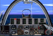
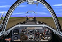
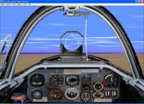
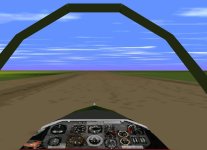
Heinkel He-162 "Spatz", 1944

aleatorylamp
Hello Hubbabubba,
A good find, the Me262 document! Very interesting.
Thanks for the He162 panel preview. It certainly is a beautiful piece of work.
I was wondering if, given the quality of the craftsmanship, this panel would warrant a separate, individual upload. This way it would stand out the way it deserves, dont´you think?
Cheers,
Aleatorylamp​

Of course, the choice is entirely yours, but consider this as my contribution to your project. I can't see that panel being used for anything but a He 162 and, as you may know, CFS1 Spatz are not plenty. I decided to concentrate on the panel as to let Ivan "spoil the sauce" with the AIR file. I'm a touche à tout (Jack of all trades) in CFS1 but, after my PC meltdown, I have to reconstruct the tools of my different trades one by one, so to speak, and gauge-panel was as good a place to start rebuilding as anywhere else.

But, again, no strings attached.

Ivan- I just saw a period picture where a Me 262 is being refueled by a bowser (truck tank). On it, written in big caracters; J2.
 
Hello Hubbabubba,

Well, well... fantastic! It will be a great honour to have your panel and gauges together with the upload as a complete package.

Ivan has been coaching me along very nicely with the .air file, and I will let him try it out again to make sure it´s ship-shape, just in case he suggests any further tweaking.

Cheers,
Aleatorylamp
 
Aleatorylamp said:
Hello Hubbabubba,

Well, well... fantastic! It will be a great honour to have your panel and gauges together with the upload as a complete package.

Ivan has been coaching me along very nicely with the .air file, and I will let him try it out again to make sure it´s ship-shape, just in case he suggests any further tweaking.

Cheers,
Aleatorylamp

He always do...:kilroy:

... but, as he hinted, final word is yours.
 
Hello Hubbabubba, Aleatorylamp,

Anna Honey is again out of town for a week so I am actually finding very little time to actually do much of anything flight simulator related.
In the last couple days, I have turned on my development machine but never actually did anything with it.
Another big problem is that the machine is so unstable at this point, that I can't even bring up FDE on it anymore.
I have a second development machine that is much more powerful but without the current projects and also without a monitor or desk space.
Ideally, I would need a KVM (and Joystick & Sound) to get it operational but failing that, perhaps I can find another way to get both machines running at the same time.

Hello Hubbabubba,

I actually know amazingly little about the Messerschmitt 262. I just pulled that bit regarding fuel out of Eric Brown's book.
If you are working on panels now, do you also have the tools to do gauges as well? I am probably going back to working on gauges very shortly to see if I can push a couple projects out. I am also working on a panel at the moment, but it is much more primitive than yours.

Hello Aleatorylamp,

I tend to be very picky with AIR files. To me, they are the subject of endless tweaking as new information comes to my attention or I learn how to do new things.
Remember that the project is yours and if it satisfies you, then that is sufficient. I tend to never stop adjusting which is why I am back in n AIR file that I last touched back in 2014. If you want my opinion, I will certainly give it, but you get to decide whether of not to adjust accordingly.

- Ivan.
 
Hello Ivan, hello Hubbabubba,

I have been following the e-mail exchange on the development of the Sparrow´s panel with great interest. Fascinating, all the details that crop up! It is interesting to see the different aspects of how the original panel itself developed at the time. Thanks for sharing the information!

I have been able to improve the model itself and the .air file a great deal in all this time. All the little bleeds related to the engine base and fuselage sides are thankfully gone. I´d also run into a bleed problems at the divisions between the 4 or 5 different fuselage section components, when viewed from steep above or below angles. From the top I was able to cover all of them up by putting a top-half only of the entire engine structure in Canopy-High Wing. Not so from underneath, however - it can´t be eliminated because of all the landing-gear, geardoor and wheel-well parts, but it is not a very usual viewing angle anyway.

Cheers,
Aleatorylamp
 
I once said to Ivan that flight simulation modelers are probably the only ones flying from frontal view. :p87:

Fiddling a bit with cannon shell's counters tonight and will send to you two guys.

BTW- Have you modified the DP file so that primary trigger should be associated to cannons? And you could adjust them to shoot a bit higher, from my point of view.
 
jets.....

So I went to Flightsim.com and downloaded an Egyptian Mig15 and
a Me262....(Galland's wingman)
probs....when a jet is far away you can only see a dot with a name
beside it most of the time.
they seem to manoeuvre like very fast bricks.
any suggestions?
>>papingo
 
Hello Papingo,

I have found that FS98 .air files used in CFS1 have a much lighter maneuverability in general, and I have the feeling that pitch, yaw and roll control has to be re-adjusted in the elevator, rudder and aileron moments, and that the moments of inertial also have to be re-adjusted. TNot an easy task, by any means! Ivan has been constantly coaching me along in the last months, as you can see!

Presumably, the FS98 .exe has a different way of calculating these things. Added to this, is the fact that with FS98, the Beckwith Gauges Stack cannot be used, so it is impossible to callibrate jet thrust more finely, which CFS1 allows to be done more accurately. This can also produce noticeable improvements in aircraft behaviour.

I suppose that with a little work on the Me262 .air file some improvements can indeed be achieved!
As soon as I have some time, I´ll give it a try. These old turbojets do have their enchantment, dont´they? Probably it´s their sheer speed that makes them attractive!!

Mind you, despite the speed, it wasn´t easy to shoot down anything with these jets because they were so fast. You only got about 2 seconds´shooting time as soon as you were in range, and if you came up from below and behind, you were immediately vulnerable to their tail gunners after your attack.

Cheers,
Aleatorylamp
 
So I went to Flightsim.com and downloaded an Egyptian Mig15 and
a Me262....(Galland's wingman)
probs....when a jet is far away you can only see a dot with a name
beside it most of the time.
they seem to manoeuvre like very fast bricks.
any suggestions?
>>papingo

Hello Papingo,

"Fast Bricks" is actually a pretty good summary of how they fly.
I have been poking around with a fantasy AIR file for my Ohka 11 which is really a heavily converted Learjet and am learning a bunch of things. (Not so much about HOW to do things but more like what values for parameters actually work well.)
As usual, there are conflicts for time with other projects I am working on and coupled with a Development Machine that is no longer reliable, it may be a while before I have anything to show.

The Jets of this time period are actually not that much faster than the last generation of Propeller Fighters, so if you are seeing them as that much faster, perhaps the AIR files are wrong which is quite possible.
Way back with the JG 57 folks, I know I did some messing around with AIR files for a Recon version of the Me 262. Perhaps I can find the work I did back then and see if it applies to the new stuff.

Aleatorylamp is quite correct in that un-edited FS98 AIR files have a tendency to be very twitchy and also seem to have very bad longitudinal trim. That is so consistent that it must be a difference in how parameters are handled in the two simulators.

One other thing worthy of note is that the Me 262 although it was fast, had only very short ranged armament in the MK 108 30 mm cannon. The hitting power was excellent but the ballistics were pretty horrible.

Need to go clean up after dinner.
Gnite Folks.

- Ivan.
 
Engine N2 Turbine RPM

Hello Hubbabubba , Hello Ivan,

The new He162 panel is certainly a beautiful one, with impressive new custom instrumentation, I must say!

There is only one issue which is giving me some difficulty, and that is the RPM gauge readout. Ivan, I´m glad to hear that you seem to be getting some clarity in the jet .air file obscurities, because perhaps with your new knowledge of gauge programming, you could possibly help out here... I hope we aren´t putting too much pressure on!

For a turbojet, N2 Turbine RPM is the parameter in question, and the default gauges all give a percentage readouts that can go up to about 110% N2, depending on how it is set in the corresponding parameter in the jet engine section of the .air file. Thus, it is not a real RPM count, but reads % N2.

I had adapted the bitmap for the dial of the Bell N2 Turbine rotor gauge, and set the ,air file parameters for an idle RPM of 2800 and a maximum RPM of about 11000, in order to get reading of the standard continuous thrust specified at 1764 flb at 9500 RPM at sea-level. At the moment, this occurs at 86% throttle position, and is the basis I am going by.

It seems to be the most reliable piece of information. Of course, the 86% throttle setting will vary with changes to the .air file parameters that set idle RPM and maximum RPM.

There was a red mark on the gauge dial at 9500 RPM. It also seems that there was a general recommendation to keep to 9200 RPM for extended periods of max. continuous thrust just in case...


Maximum 30-second 2028 flb thrust is insufficient for the model to attain performance consistent with specifications at any altitude, and at least 2182 flb seem to be needed, to get a reasonable Boost-envelope. RPM is generally quoted here at 11500 RPM, but will of course vary with altitude. Inexact readouts here will not really matter, as Boost was only allowed for 30 seconds, and could only be used few occasions during a flight.

The main thing is, that with Hubbabubba´s newly made authentic dial, the needle is at the wrong angle.
Possibly a bit of gauge programming could fix it so that it fits the basic specified normal max. 1760 flb thrust at 9500 RPM, which is what I suppose a pilot would go by.

Here´s a screenshot that includes the Beckwith Gauge Set, showing the thrust values, my own adapted RPM gauge showing the 9500 RPM, and the N1 - N2% Standard jet gauge as reference, in comparison to the new gauge.

Hubbabubba: Sorry about messing up your beautiful new panel in the screenshot with all the extra ugly stuff!!

I wonder if you would have any thoughts on this?

Cheers,
Aleatorylamp
 

Attachments

  • N2 turbine panel.jpg
    N2 turbine panel.jpg
    112.7 KB · Views: 1
"Fast Bricks" - Me-262 speed trials.

Hello again,

Papingo´s coments on "fast bricks" spurred a little investigation into the FS98 Me-262 .air file. At first I had found Rabbidja Guder´s example .air file that came with the original AF99 CD, but unfortunately I was unable to stable its constant soaring, so I settled for the .air file that comes with Berndt Drehfalhl´s Me 262.

This one was rather easy to stabilize, and I found that it was rather souped up:
It was doing 587 mph at S.L., with 105% N1/N2, (thatever that would mean as turbojets are single-spool, both compressor and turbine running at the same RPM), and thrust was also a bit high, at 2496 flb.

S.L. specification states 1980 flb thrust at 8700 RPM, and 560 mph max. level speed. Presumably, this would be a maximum continuous speed, and there is no reference to any kind of short-duration extra power coming from boost-bursts or afterburners.

I managed to tone it down a bit by reducing the thrust entry and tweaking the RPM entries for idle (3000 RPM) and maximum RPM, and after this I got a more reasonable S.L. performance of 560.7 mph with 2212 flb thrust, and then I also got a very plausible 90% power performance of 526 mph at 1871 flb thrust, with 97% N1 and 101% N2.

However, one thing which is turning out to be very difficult to adjust, is to get the maximum RPM down to 8700 RPM corresponding to full power. At the moment it is at 10000 RPM.

Update:
There is a clarification to this respect: Remember that the N2 Turbine gauge gives %RPM, not real RPM, so in this case, 10000 is really 100% of full RPM - so changing the scale to have 8700 RPM at this position would solve the dilema. Using the default N1/N2 B737-400 gauge, when N1/N2=100% thrust is just over 2000 flb, very near the specified 1980 flb for max. continuous. I doubt whether the simulator .exe could ever give a real N2 RPM value, as it seems only to function with %RPM. So, the dial would have to be doctored in such a way to read 8700 RPM here. Of course, the position of the needle compared to the real RPM instrument is quite another matter, as would be the range of the scale on the dial.


Anyway, perhaps the FD can be of help for Papingo, so I have included the modified .air file with this post.
Cheers,
Aleatorylamp
 
Last edited:
Another trove worth reading; THIS SITE!!! :redfire:

In it you will learn quite a bit. I was particularly interested by jet starting procedure (spoiler alert);
Starting procedure is as follows: Starting engine is primed by closing electric primer switch, then ignition of turbojet and ignition and electric starting motor of Riedel engine are turned on (this engine can also be started manually by pulling a cable). After the Riedel unit has reached a speed of about 300 rpm, it automatically engages the compressor shaft of the turbojet. At about 800 rpm of the starting engine, starting fuel pump is turned on, and at 1,200 rpm the main (J*2) fuel is turned on. The starter engine is kept engaged until the turbojet attains 2,000 rpm, at which the starter engine and starting fuel are turned off, the turbojet rapidly accelerating to rated speed of 9,500 rpm on the J*2 fuel. During acceleration, pilot must observe closely the functioning of the governor, also temperature of the hot gas in the thrust nozzle — which must not exceed 750°C.

and jet control;
Object of jet control is to coordinate the three principal variables — turbine rpm, fuel flow, and exhaust nozzle area — so that optimum efficiency may be obtained at all altitudes without exceeding maximum allowable turbine blade temperature. For this purpose, fuel flow and rpm are integrated by a constant speed governor. Strength of the control spring in the governor depends on the throttle position. A special accelerator valve allows for the inertia of the turbine and compressor when the throttle is opened too rapidly or abruptly.

When pilot opens the throttle too fast, an aneroid, controlled by the pressure difference across the compressor, opens a bypass for the excess fuel until a predetermined rpm. is reached. This method precludes an over*rich mixture during initial acceleration, thus avoiding over* heating. Since faulty operation would lead to serious overheating of the turbine, a safety device is included to connect throttle linkage to exhaust nozzle area control mechanism so that a progressive opening of the throttle for climb automatically closes the exit to the appropriate position. This operates in the opposite fashion when the throttle is closed for landing or shutdown.


Exhaust nozzle area has these manual controls: Position A — starting and idling, largest opening, (186 sq in); position S — intermediate position for climb (155 sq in); position F — high speed flight position (147 sq in); and position H — high altitude flight position (163 sq in).

This solves many questions concerning a variety of subjects and, after thorough reading (I made a PDF of the document), I went back to the Bedienungsanleitung where the 25 L starter fuel tank (probably B4) was stored in the right wing. It had a volume capacity of 30L but, probably for expansion, was only filled up to 25L.

This also poses new problems, especially for RPM of the compressor (tachometer was taking indirect readings from that shaft). Over 6,300RPM, the governor was controlling RPM to stabilize revolution at operating 9,500RPM. So throttle % had only real effect on RPM<6,500. Passed that point, the governor acted as a limiter-controller.

Anyway, good reading...
 
Hello Hubbabubba, Hello Ivan,
Thank you very much indeed for this very interesting document! It also supplies extra specification details for the extra boost power.

I don´t understand what you mean with: > This also poses new problems, especially for RPM of the compressor (tachometer was taking indirect readings from that shaft). Over 6,300RPM, the governor was controlling RPM to stabilize revolution at operating 9,500 RPM. So throttle % had only real effect on RPM<6,500. Passed that point, the governor acted as a limiter-controller.<

Being a single-spool turbojet, i.e. only one axel with both compressor and turbine, the governor would surely limit both compressor and turbine simultaneously - both would have the same RPM all the time, and as turbine output is given with N2 %RPM, surely this would serve as an accurate enough instrument on the panel, if it could be programmed so that the needle would fit into the operating range of the scale. The red marks on the authentic gauge would be the guideline.

I doubt the last that bit you mention: >
Exhaust nozzle area has these manual controls: Position A — starting and idling, largest opening, (186 sq in); position S — intermediate position for climb (155 sq in); position F — high speed flight position (147 sq in); and position H — high altitude flight position (163 sq in). < can be implemented, so only a general approximation to the engine´s operation envelope will be possible, but it´s quite OK by me, as far as things go given the sircumstances, so I´d be more than satisfied if the RPM gauge issue could be fixed!

I wonder if Ivan would be able to give any information details on the way the N2 %RPM are given in the actual programme of the gauge itself.

Anyway, it is definitely a fascinating journey of research into the early jet-age technology!
Cheers,
Aleatorylamp
 
The problem is quite simple; the only way to control RPM, at least that I know of in CFS1, is through throttle. As, in "real life", that throttle control ceased at 6,300RPM (it was a typo on my previous comment), and would automatically raise, and stay, at 9,500RPM. how could we mimic that with the needle deflection?

Add also the "burst" action that you wanted to use. It would certainly show on the RPM, and it should not.

It would have been the same problem with a constant speed propeller but, at least, CFS1 AIR files could deal with that. I doubt that the FS98-style jet AIR file can.
 
Hello Hubbabubba,

OK, I see. It also appears that the 6300 was the recommended minimum RPM during flight to prevent blowout, (the absolute minimum was 6000), and the 2800 RPM idle was only used on landing. This automatic throttle control is as you say, of course impossible to mimmick, and there´s no way to separate the burst power from the normal throttle range either. The 9500 RPM maximum continuous power has different throttle settings depending on altotude. However, there seems to have been a kind of safety margin here, and I have seen references here as to normal operation range being +- 300 RPM, i.e. 9200 - 9800 RPM. So a pilot will not have to check this to be exactly 9500 all the time. Here, the only way to do it is to tap keys F3 or F4 a few times and wait a bit for the turbine RPM to adjust itself to the 9500 RPM, if one wishes to fly at this maximum speed. Shorts cuts would be the "8" key, giving 80% power which has a greater safety margin.

But I wasn´t really referring to these things, only the needle deflection itself, to try to get it to point to the correct numbers.
However, if this isn´t possible, then the only alternative is to use my bitmap, or one llike mine. I´m correcting the upper red zone to make it shorter, more similar to the original photos. This bitmap already gives correct readouts for maximum continuous, minimum flight RPM and idle RPM, so it would be quite convenient to use, I feel.

Of course, should you wish to alter the bitmap in your gauge to make it similar to mine, I´m sure that it will look more authentic, because you seem to be much better at this kind of thing!

Cheers,
Aleatorylamp
 
I have two candidates that could be morphed to give 9,500 RPM at 80% without having to change the graduations excessively. Would it do?

I'm trying here to get as precise a reading as can be while keeping as close as the actual gauge appearance. Having my cake and eating it too so to speak...
 
Model ready. and corrected RPM gauge bitmap

Hello Hubbabubba,

Here´s the Sparrow model in its probably finished state now.
It includes your new panel but with my corrected N2 Turbine RPM gauge. The gauge is in the aircraft folder.

Performance of the model and RPM readings are as follows:

Sea Level: 3000 RPM Idle, 219 flb thrust.

500 ft level flight:
86% throttle: max. continuous 9500 RPM, 1764 flb thrust
497.8 mph. (6.8 mph fast)
100% throttle: Boost burst 10600 RPM, 2175 flb thrust (2028 flb is too low to maintain boost performance)
551 mph (2 mph slow)

20000 ft level flight:
81% throttle: _9500 RPM, _994 flb thrust, 491.0 mph (9500 RPM obviously insufficient here)
94% throttle: 10300 RPM, 1124 flb thrust, 522.0 mph (spec. non-boost speed)
100% throttle: 1800 RPM, 1282 flb thrust, 563 mph (1 mph fast)

A panel screenshot is also attached to this post - and the "corrected" gauge bitmap. It seems to look OK to me. What do you think?
I have also included the N2 RPM gauge in the aircraft folder.

All in all, the absence of the F10 Boost option for jets that is normally avaliable for CFS propeller planes is not too terrible, as it is actually quite practical for normal high-speed flight to be flying at 80 or 90% throttle.

Update:
It would be interesting to see the two versions of the dial that you have made - they may be better than mine because I have the feeling I made the red/white band along the periphery a bit too broad.

Cheers,
Aleatorylamp
 

Attachments

  • Spatz-Panelshot.jpg
    Spatz-Panelshot.jpg
    96.2 KB · Views: 0
  • Spatz BMW N2 Rotor.bmp
    90.7 KB · Views: 0
Last edited:
Panel and Instruments ready!

Hello Guy, Hello Ivan,

After intense cooperation on the part of you both, the panel and instrumentation have indeed turned out fantastic!
Ivan did a great job reprogramming the N2 Turbine RPM needle so as to make it point to the correct dial numbers on Hubbabubba´s realistic new dial-bitmap, and it gives very accurate readouts now. More than satisfying... Excellent!

Here´s a screenshot of Hubbabubba´s new panel, with the extra gauges - Below on the right two ammo counters are to be seen! ...good to keep track of the bullets which are left, as there are only 120 for each of the two 20 mm cannon.

I also prepared a new dashboard texture from the new panel, so that the virtual cockpìt on the model now also looks correct.
Here´s a screenshot of that too.

So, soon there will be a new upload for the now improved He-162 jet. Other improvements include the flight dynamics and reduction of bleeds. I´m just going over the accompanying text files and preparing the SCASMing for the V-Cockpit view correction. Before uploading I´ll back check with you so as to avoid any errors.

Thanks again for the good teamwork!
Cheers,
Aleatorylamp
 

Attachments

  • Spatz-newpanel.jpg
    Spatz-newpanel.jpg
    104.2 KB · Views: 1
  • Spatz-Vcockpit.jpg
    Spatz-Vcockpit.jpg
    52.3 KB · Views: 1
f86

well I went back to flightsim .com .
I put in 'sabre' into search box.
I got 3 responses
f86
super sabre
another sabre .dp
Anyway the f86 sabre handles very well.
I would recommend it!
at least I've managed to damage a Mig
luv to all
>>papingo
happy birthday to Ivan
 
Last edited:
Hello Papingo!

I´ve checked out the Sabre - I got Shigeru Tanaka´s F86F with moving parts. It looks great and flies very nicely. Like you say, it handles very well!
Nevertheless technically, it´s not too exact, as high performance is a bit off. Max. speed is only 622 mph at full throttle, and should be 687 mph. Then, max. thrust is too high at 7750 flb, being quoted at 5910 flb.
I tried to correct it, but only got the thrust better by entering 6357 flb. Now it´s reading 5934 flb at 100% N2, (90% throttle), but speed correction is more difficult. Even reducing the Drag quite a lot, I only got about 10 mph more at N2=106% (100% throttle) and 6357 flb thrust. I always find it a bit tricky to fit the high speeds to the specified values with CFS using correct thrust entries, and this gets more pronounced at altitude.

Hello Guy, Hello Ivan,

Well, it looks like after all the help that I´ve obtained, the Spatz Upgrade is quite ready for an upload soon.

Cheers,
Aleatorylamp
 
Last edited:
Back
Top