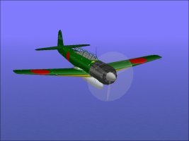
Nakajima C6N1 Saiun "Myrt" Recon Plane

Nakajima C6N1 Saiun "Myrt" Recon Plane 1

No permission to download
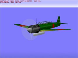
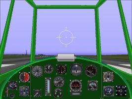
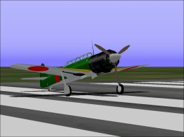
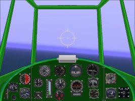
This was an aeroplane I found a week or two ago after testing gauges on my Game Machine.
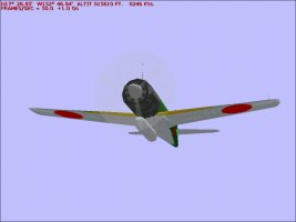
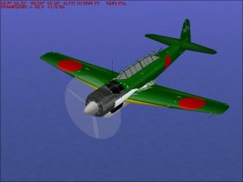
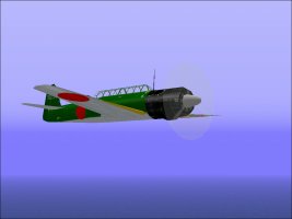
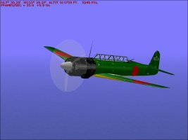
It is a fairly nice visual model for CFS though the flight model seems to be the FS98 type and does not have the proper performance at altitude.
This was easily the fastest carrier plane used by the Imperial Japanese Navy during WW2 and in some models was capable of around 400 MPH.
This model which can be recognized by the 3 bladed instead of 4 bladed propeller was "only" capable of around 380 MPH.

My plan is to provide a reasonable AIR file as a patch at some point along with some more suitable gauges for the panel.

- Ivan.
C6N_1.jpg
C6N_2.jpg
 
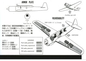
Attached are some images with some basic information about the C6N1.
Note that each wing has 4 individual fuel tanks. Since we really can't handle that configuration in a CFS flight model, each wing will have a Main (inboard) tank combining the leading edge and inboard fuel tanks, and a Aux (outboard) tank combining the mid and outboard wing tanks.
For flight model purposes, we will be ignoring the external fuel tank which is 192 US Gallons.
Personally, I would have left off the external fuel tank in the model because it is the only place with a serious bleed.
Note that the fuel tank is offset to starboard. I believe this is to give extra clearance for the oil cooler on the port side under the cowl.
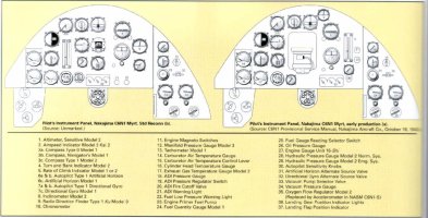
Attached also is a typical panel configuration for the recon C6N.

- Ivan.

C6N_3.jpgTAIC_Diagram.jpgC6N_Panel_StdRecon&NightFighter.jpg
 
Although this is a fairly nice visual model, the flight model could use some serious work as mentioned before.
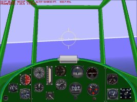
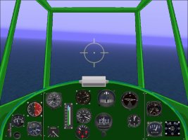
In the previous screenshots, the speed of 247 Knots which is shown is with full power and flying straight and level at 15,000 Feet.
This works out to about 275 MPH which is about 100 MPH lower than it should be. There is no way to easily correct this with a FS98 AIR file, so a CFS type AIR file is being developed.

As with most higher powered Japanese aircraft, Emergency power is a strange thing.
The total internal fuel load for the C6N1 was 1356 Liters. For that amount of fuel, the aircraft also carried 150 Liters of Anti-Detonant (Water Methanol). ADI would automatically begin at just above Maximum Continuous power (+180 mm) or only 37.0 inches Hg.
Was there anything special between Rated Power of +350 mm and Take-Off Power of +500 mm? I am not sure.

We shall see how the flight model works out.

- Ivan.
 
I had entered most of the known parameters for a C6N1 into a CFS AIR file a couple nights ago.
This is a VERY tedious task because about 90% of the records are affected in one way or another.
The first test flight showed that the "New" AIR file was giving only about 980 HP at 5000 Feet.
Yes, I ran the first test at 5000 Feet because that was not too far from the low speed supercharger peak horsepower.
Obviously this was not even close.

I had started with a pretty reasonable P&W R-2800 from a previous project and just modified the geometry.
This is an interesting topic worthy of note.
The R-2800 engine actually displaces 2804 Cubic Inches and generates around 2000 HP at Sea Level running at 2700 RPM.
The Ha-45 Homare displaces around 2160 Cubic Inches and generates around 1980 HP at Sea Level running at 3000 RPM.
It also does this with substantially less manifold pressure. We may get into a description as to why this is possible later.

Last night after posting here, I worked on tuning various engine parameters to get closer to the proper performance.
Keep in mind that before doing this, I had already pulled useful pieces from several other AIR files I had done in the past.
I had not planned on doing a proper "Ivan's Propeller Factory" type of propeller for this project but the Propeller Power Coefficient is so close to that of the Ki-61-Id that I just lifted the propeller tables from that aircraft. They may need slight modification but there is nothing obviously wrong yet.
The existing fuel tanks were discarded and fuel tanks from my P-38J Lightning were installed. No problems encountered there.
I ran into a minor issue with Propeller Animation and pulled some data from one of the FW 190D AIR files I had done. It wasn't directly useable but with some slight modifications, everything worked.

As usual, the first step was to get Sea Level power (500 Feet) more or less correct.
I was trying for a Take-Off power output (+500 mm) 49.6 inches Hg of just under 1950 HP
The Rated power (+350 mm) 43.7 inches Hg was whatever it was going to be.
Power at 500 Feet
Take-Off 1923 HP
Rated 1653 HP

Keep in mind that this is the typical military engine and we are trying to simulate a Two Speed supercharger with a CFS AIR file which really is simulating a single speed supercharger. There will be mismatches in power, especially in intermediate altitudes.

Here is a coarse table of HP versus Altitude.
There is no point in taking smaller altitude steps when just doing basic tuning.
The interest is at 6000 Meters (19685 Feet) and the most likely power / speed peak below that.

Altitude Rated Power Take-Off Power
500 Feet 1653 HP 1923 HP
5000 Feet 1718 1997
10000 Feet 1795 2085
15000 Feet 1878 HP No Supercharger Capacity for Take-Off Power
17500 Feet 1708 HP No Supercharger Capacity for Take-Off Power

Note that in an actual engine, the power output at 10,000 Feet and 15,000 Feet are too high.
Low Blower has run out of capacity and High Blower has not reached its peak power yet.
Unfortunately, that is not how CFS works, so we have to live with it.

Speed at 15,000 Feet is 384 MPH
Speed at 17,500 Feet is 376 MPH

This is definitely in the correct range. I got a bit tired and quit testing after this.
There needs to be more testing at 19,000 Feet and 20,000 Feet and perhaps some minor adjustments depending on results.

- Ivan.
 
I went back tonight to fill in some of the blanks and see where changes need to be made.

500 Feet ----- 1653 HP ---- 1923 HP ----- 314 MPH (350 MPH at Take-Off / Emergency Power) Prop Pitch 33 Degrees at Rated Power
5000 Feet -----1718 ------- 1997
10000 Feet ----1795 ------- 2085
15000 Feet ----1878 HP ------------------- 384 MPH Prop Pitch 39 Degrees
17500 Feet ---- 1708 HP ------------------ 376 MPH Prop Pitch 39 Degrees
20000 Feet ---- 1540 HP ------------------ 365 MPH Prop Pitch 38 Degrees

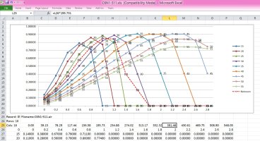
This suggests that the Propeller Power Coefficient is a pretty good match. (The simulator is not picking any angles that are obviously too fine or too coarse.) The general efficiency table seems pretty much working......

See attached spreadsheet. Note that speed at altitude generally corresponds to Advance Ratio J = 1.9.
That doesn't mean there is nothing wrong with this efficiency table. The transitions are not really very good.
Note the Red Dashed line for 27.5 Degrees. It is a fairly lousy compromise between 25 and 30 Degrees but that is how the simulator works.
Most of these transitions are in places where minor (or even major) adjustments make no difference in performance.
Note that these tables were lifted from an old Ki-61 project with no modifications. That project had the first propeller ever manufactured by Ivan's Propeller Shop and technicians back then were much less experienced. They learn more with each project.

- Ivan.

C6N1_Efficiency_Original.jpg
 
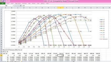
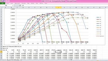
Attached are the original and revised Propeller Efficiency Tables.
The Red Dashed line represents 32.5 Degrees Pitch. This is pretty close to 33 Degrees Pitch which is used at maximum speed at 500 Feet.
If one examines the graphs at Advance Ratio J = 1.6, there are a couple things that can be seen.
First, the propeller should have already switched to 35 Degrees pitch to maintain optimum efficiency. This shows a mismatch in the Propeller Power Coefficient Graph but I do not believe a perfect match with Table 512 is really possible at all altitudes anyway.

The second issue is that the Propeller Efficiency is only around 65% in this interpolated graph.
The revised graph has transitions with fewer jumps between the different angles. It would be perfect if the actual transitions between angles actually happened at those Advance Ratios as they did not at Sea Level maximum speed. Note that the Propeller Efficiency is now around 79% which is still not ideal but not bad when the transition is that far off.

- Ivan.

C6N1_SL_Efficiency.jpgC6N1_SL_EfficiencyRevised.jpg
 
After changing the Propeller Efficiency Table, the speed at 500 Feet at Rated Power increased from 314 MPH to 322 MPH with no other changes.

A quick check of the Power and Speed at 20000 Feet (6100 M) which is the critical altitude of this model engine at Rated power showed that both power and speed were too low. I don't actually expect to correct ALL of the discrepancy because it would make the performance at medium altitudes way too high.

Here is the result:
500 Feet ----- 1653 HP ---- 1923 HP ----- 322 MPH (350 MPH at Take-Off / Emergency Power) Prop Pitch 33 Degrees at Rated Power
5000 Feet -----1718 ------- 1997
10000 Feet ----1795 ------- 2085
15000 Feet ----1878 HP ------------------- 390 MPH Prop Pitch 39 Degrees
17500 Feet ---- 1772 HP ------------------ 389 MPH Prop Pitch 39 Degrees
20000 Feet ---- 1604 HP ------------------ 373 MPH Prop Pitch 39 Degrees

It is still a touch slow at 20,000 Feet, but not extraordinarily so. It is about 10 MPH too fast just below that, but I will settle for this combination.
Next tests are for general handling, and climbing speed and ceiling. Initial climb is not well documented but service ceiling is.
There are still numerous sanity checks for handling and general bad behaviour.

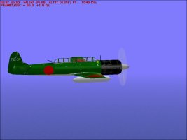
Screenshot is from a speed run.
"The Grummans can't catch us!" is a quote from a C6N crew member.

- Ivan.
GrummansCantCatchUs.jpg
 
I hadn't thought this would get to be such an involved project.
Just finished programming three new gauges for this panel. I am sure those gauges will be reuseable at least in part, but that was an awful lot of messing around with gauges when I was trying to take a break from them.

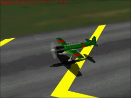
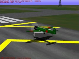
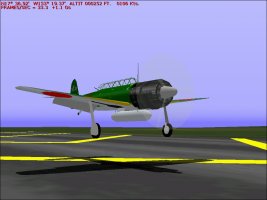
A couple days ago, I decided to see how hard it was to actually land this beast.
Turns out it is amazingly easy..... Until you apply the brakes. Then it flips over in a second.
Time to adjust the braking factor as per the thread "Braking News".

Plenty more left to do and I didn't even build the model.

- Ivan.

C6N1_Slow1.jpgC6N1_Slow2.jpgC6N1_Slow3.jpg
 
This is the thread "Braking News":
Someone ought to make it into a sticky.

I just finished adjusting the Scrape Points to match the Model.
I found out that the model isn't nearly as good as I had thought.
Here are the obvious problems:
1. The CoG is a bit too far forward. It isn't that much, perhaps around 15 inches or so in my opinion.
2. The Wing Span is around 11.65 Meters. It should be 12.50 Meters. I needed to check this for scrape points.

The initial Braking Factor was -4000.
As discussed in the thread "Braking News", this is effectively 61,500.
I adjusted it down to 30,000 and was completely unable to plant the aeroplane on its nose.
Next step is to check the landing gear contact points and then fine tune the Braking Factor.

- Ivan.
 
A Braking Factor of 30000 is actually quite high, so I was surprised that I could not cause a noseover.
The next step was to confirm that the Landing Gear contact points were correct.
I had simply lifted them from the original AIR file because I believed the author would have enough good information to get that correct and because the aeroplane did not wiggle or fidget when sitting on the runway.
Turns out I was wrong. The contact points didn't really match the model all that well.
The Main Gear was about 1.5 FEET too far forward which explains why it was so difficult to noseover.
The Main Gear track was way too narrow which did not make sense at all.

With the Landing Gear contact points corrected, the aeroplane now can noseover with a Braking Factor of 16000.
Next comes the checks for Climb Rate.

- Ivan.
 
Here is the current status of the new panel with a few new gauges.
The Manifold Pressure Gauge is now a 500 mm version instead of the 400 mm version borrowed from the Ki 61-Id.
The Air Speed Indicator still does not look like the actual Japanese version that uses two revolutions to indicate the full range, but it does start about the right place and end about the right place.
The Fuel Selector is new. The Fuel Quantity Gauge is from the stock Bf 109E.
The Inclinometer is new.
Note that neither the Fuel Selector nor the Inclinometer actually work correctly at the moment, but the appearance is generally correct.
The arrangement of instruments will change a bit as more are added. The general arrangement isn't going to be terribly close to the actual panel.
There are too many gauges that do pretty much nothing in CFS that are included there.

- Ivan.

C6N_GaugeTest.jpgC6N_NewPanel.jpg
 
A little explanation might be in order regarding the "Gauges that do pretty much nothing in CFS".
The late war Japanese aircraft just about all used 50-50 Water-Methanol injection to prevent detonation at higher boost settings.
Anti Detonant Injection (ADI) was necessary not just for "Emergency Power" but for just about any power setting above maximum continuous.
This was because the standard Japanese fuel was only 91 Octane in the Navy (92 in the Army) and was used for fairly high powered engines for which other countries would use fuel with octane ratings (Performance Numbers) of 120-150.
Running out of ADI while it was in use was bad as in engine destroying bad. That is why on the C6N and other aircraft there were gauges for ADI quantity, pressure, flow rate, etc. None of these gauges have any meaning in CFS since we really don't measure ADI flow rate.

Around the airfield where I do my testing, we seem to have had a rash of thefts.
The rather large drop tank on the C6N1 was the latest victim.

- Ivan.

DroppedTank.jpg
 
Finally got the Inclinometer Gauge working.
I am not sure the indicator is coloured particularly well, but it is easy to read at this point.

- Ivan.

NewInclinometer.jpgC5N1_WEPClimb.jpg
 
Attached are screenshots of the updated panel.
There are still some issues with a couple gauges such as the Type 92 Compass and the Manifold Pressure gauge.
The compass is an interesting thing. The outside ring is now manually set as the original was. Things that are not noticeable when it just indicated heading are quite noticeable when it is manually set.
The markings on the Manifold Pressure gauge just don't quite look right to me. The tick marks are a bit fuzzy which probably isn't noticeable at the scale that it is displayed on an actual panel, but I know it is there.

The real aircraft had an interesting autopilot which I was thinking of trying to program, but although the bitmaps are easy, it is yet another unpredictable delay if I should do that.

- Ivan.

C6N1_PanelV1.jpgC6N1_Flightline.jpg
 
Back
Top