P-47 Progress Thread

There are three lines in the cockpit m3d that define the interior glass referencing scratches_reflection.dds (FF FF 0E 00 FF FF), or ACC_P47DQQ_XXXXXX_GaugesGlass_s.dds (FF FF 12 00 FF FF). The problem with the way they are currently entered is that they need a diffuse texture reference (first position after the glossiness numbers) to go along with the specular texture reference (second position after the glossiness numbers). Changing them to (0E 00 0E 00 FF FF), or (12 00 12 00 FF FF) respectively clears up the issue.

Alternatively, you can leave them without any diffuse or specular texture reference (FF FF FF FF FF FF) after the glossiness numbers (00 00 00 00 00 42), and get the same result.
 
Ah, so that is it!

I had these diffuse materials unticked and set to '0' in gmax but apparently that doesn't work (I just found a thread that it is possible to remove a map in 3DS Max but not gmax). So I have to create a new material without a diffuse material...

Thanks!! :encouragement:
 
I missed the boat on the first round, but it does look very nice! I'm curious how your work with the materials in the VC will affect things when you start adding specular textures. It may get complicated. I'm not sure how you set it up on the gmax side of things, but when I hex edit an m3d, there are four main parts I adjust:
Transparency
A tag which causes CFS3 to treat it as a reflective part or not, which increases the strength of reflections
Specular strength
Specular sharpness

For ease of working with specular textures, I try to set standard values of specular strength, so that specific shades in the greyscale specular textures produce consistent levels of specular output. If you are using a lot of different values here for different materials in gmax, you might be making more work for yourself, since this will be modified again by the specular texture. The specular sharpness cannot be changed by the specular texture, so this is where I suspect your work with materials will help you achieve the desired results.

I need to think this over and experiment a bit - maybe the metal export problems arise from my use of shaders (and their settings) in combination with the _s and _r textures.

What I did was selecting the 'blinn' shader for non-metal parts and changing the 'specular' and 'gloss' settings using PBR values I found on the web in hopes of achieving a similar effect (CFS3 doesn't support real PBR). I was hoping that I could influence/finetune those basic gmax settings with the specular or reflective textures. I used the metal shader for bare metal parts. But perhaps using just two shaders (metal and blinn) without a lot of different multi-material settings to distinguish between different material properties is enough and have the textures do the rest.
 
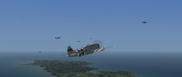
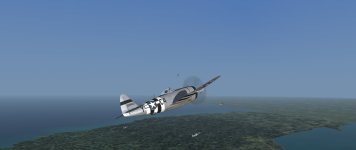
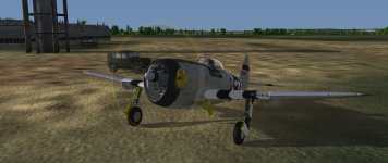
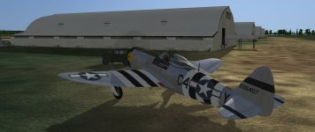
Preview update!

Just in time for the end of the month I'd like to share an update for the Christmas 2023 preview of the P-47.

The prime motivator for this was the piece of cowl flap webbing that got misplaced on the external model and the files provided by Rene and Andy. Another one would be the fact that if something would happen to my files (or to me), you'd be left with a unfinished virtual cockpit - specifically the still unwrapped/untextured parts that would seriously bring the immersion factor down. So wherever I could, I either finished, updated or deleted those parts and updated/altered their textures.

The FM has been updated by Rene to v4.00 standards. The range arcs and limits on the gauges differ somewhat from the previous version (which were actually those for later models), so the needles may appear to be off on some of them (eg. the fuel and oil pressure needles). This problem may be addressed in the future.

Inspired by the +clight files posted by Andy, I reviewed all info I could find on the gauges, placards and cockpit decals to determine which ones were radium painted/UV reactive and which ones were simply black and white. The new +clight textures included in this update should reflect the results.

On top of that, you'll get a new weapon: the M10 Triple Rocket Launcher with the M8A1 rocket.
The Triple Rocket Launcher was developed to enable the M8 rocket to be used as an air-to-ground weapon. It came in three versions, the M10, the M14 and the M15, which differed predominantly in the material used for the launch tubes (plastic, steel and magnesium alloy respectively) and, as a consequence, in weight. Being plastic, the M10 cluster was to be discarded after 5 launches - before it could rupture or generally become too unreliable in use.

The M8A1 was a 4.5in solid fuel rocket with a ca. 4.3lb explosive charge, weighing approx. 40 lb as a complete weapon. It was stabilized in flight by six fins that flipped up once the projectile had cleared the launch tube. Muzzle speed was 850ft/s with a maximum range of about 4,600 yards. The explosive effect was comparable to that of the 105mm artillery shell M1.
[Data: TM9-395 4.5" AIRCRAFT ROCKET MATERIEL, 12 September 1944]

An installation readme in .txt and .pdf format is included.

As before, the WeTransfer link below is valid for only 7 days, so get it while it is still there: https://we.tl/t-jjyYeciw3d
 
Your P-47 is fantastic. You have wet my appetite ! Can't wait to see the finish product. Keep up the wonderful work , and thank you so much for the time and effort put into this labor of love . Regards, Scott
 
Glad you like it, guys!

@Scott: The .jsgme file is a descriptive text file for people who use the JSGME program to install/uninstall mods. If you don't use that program, you don't have any need for it and can ignore it when coying the P-47 files.

BTW, there won't be a February update: I was a little tired of working on it and wanted to take some time off. Hopefully there will be a March update with new goodies... :untroubled:
 
Great Frosty ! Can't wait for the new update. Loving the wonderful P-47D and been really putting it to the test. Thank you so much for making a long time dream come true ! Regards Scott
 
Just checking on how things are coming along ? So excited about the series you are doing. ! Regards ,Scott

Sorry, nothing new to show/report yet but I am working on an improvement of something that's already in ETO (and ties in a little with some of the P-47s).
 
While you guys were busy decorating our new hangout, I was checking some P-47 cockpit stuff when I realised that much of the cockpit equipment in the preview D-25 aircraft are leftovers from the D-30/-40 model that I originally planned to do. So, when I studied the general arrangement blueprints, I realised that I had simply modeled a lot of the parts after what I had seen on period photos and films. These particular blueprints however, list all the equipment installed in the various submodels in a table on the side, so it would have been much easier to have started from there! While I mostly worked my way up from individual component blueprints to (sub)assemblies and finally to installation blueprints (which meant a LOT of searching in the library), it would have been much easier to go the other way around! :banghead: (Future modelers take note here! :sneaky:).

Anyway, it turns out that the radio equipment you see in the preview model was not factory installed in the D-25. The snag I encountered was that I not only had to model a new radio installation but also that the D-25 could be equipped with TWO different radio combinations! So double the work!
The D-25 was equipped with either the SCR-274/SCR-515 radio sets or the SCR-522/SCR-695 combination, of which the last one could also include the Detrola beam receiver that's currently visible in the cockpit. The former combination did not the include the Detrola and the mounting space was blanked off with a metal plate.

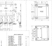
Trouble is, where to find reliable dimensions/blueprints for all these radio components? Although I have found most for the individual SCR-274/SCR-515 components, there's one elusive control box: The BC-646 and its FT-256 Mounting Plate. I did find the approximate dimensions of 4 1/2 by 4 1/4 by 2 inches but 'approximate' is not quite good enough (eg. is it just the box itself or does it also include the side mounting points etc?). If anyone could help me to a drawing of this control box, I would be much obliged. Below you find a web screenie of the box itself and an example of the type of drawing I am looking for (the box is listed as BC-646 but was also known as the CG-23ABJ or (component of) the ABA-1 in the Navy):
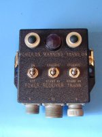
BC-646.jpg

Dimensions SCR-274-N Control Boxes.jpg


And finally a gmax screenie of the SCR-274/SCR-515 cockpit arrangement (still without the interconnections - and the BC-646, of course):
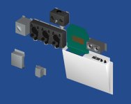
Teaser63.jpg

The BC-646 should be mounted to the right of the BC-765 Switch Box Detonator. The white part below is the mounting for the Map & Data case which I included to show the positions of the toggle switch and the two fuse storage posts and above that is the plate to blank off the Detrola mount. The other parts are, clockwise from the bottom left, a Terminal Box, FL-8 filter, BC-451 (Control Box Transmitter), BC-450 (Triple Control Box Receiver) and lastly, at the bottom again, a MC-385-B (Adapter Headset in a custom mount).
Now the tedious job of unwrapping awaits (the painting is much more fun) and then on the the second set...

Oh wait, did I mention that the D-28 has yet another set? Yes, it does (SCR-274N/SCR-695/MN-26 combination) and only after that one we can finally proceed to the D-30/-40 model. Sigh...
 
Last edited:
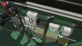
Getting there with the SCR-274/SCR-515 cockpit controls :

Teaser64.jpg

The control boxes and most cable plugs are unwrapped and arranged on a texture sheet, so that leaves the cables themselves and some of the remaining plugs to be done.
There's also a very few minor parts to be modeled (some bolts and nuts etc.) but this set is getting close to the finish!

And I found some time to take a screenie from the driver's seat:

Teaser65.jpg
 
Last edited:
Back
Top