Reworking Eric Johnson's Airacobra

Ivan

Charter Member
Hello All,

I first encountered Eric Johnson's P-39D Airacobra a bit over 15 years ago.
Perhaps it was actually someone else's modification of his original design. It has been so long I can't remember.

This was way before I started building Aeroplanes for Combat Flight Simulator and most models of the time were adaptations of Flight Simulator 98 (or earlier) designs.
I thought the general shape was pretty good even though it was obviously a very low polygon 3D model.

It did have some obvious faults.
Some were obviously a consequence of the low resource count and a possible lack of tools at the time.
The worst fault was that it had "Plain Flaps" while the actual Airacobra had "Split Flaps".

There were a few shape issues the worst of which was the angle of the aeroplane while sitting on the ground.
The Airacobra sits at a very noticeable nose high attitude.
At the time, I was just getting into editing AIR files, so correcting the angle on the ground was not difficult.
The end result was that "my own version" of the Airacobra at that time would always sit with the Nose Wheel hovering a few inches off the ground.

.......

A couple years later not long after I started attempting my own projects with Aircraft Factory 99, I found the AFX for Mr. Johnson's Airacobra. I also found many other AFX's but really had no idea what to do with them.
With Mr. Johnson's Airacobra, I decided to try a few "simple" edits.
The Plain Flaps bothered me the most, so it was the first correction.
The next edit was to replace the 2D Wing Guns with 3D pieces.
After that, I quit. Following the Parts naming convention in EJ's AFX was quite difficult.

That is where things stood for many years. I had an updated Eric Johnson Airacobra on a couple computers but since it was not my own original work (nor was the work that great an improvement), I never uploaded it.

.......
 
Airacobra Revisited

....About 6 months ago, I started getting involved in several technical discussions about the Airacobra on another forum. Over the years, I had collected a fair amount of information on various versions of the P-39 / P-400 / Airacobra and even had done a few calculations to see if I could figure out where the Center of Gravity could migrate to under operational conditions.

A few months ago, while working on edits for my P-47D-25, I decided to go poking around at other AFX's on my Development Computer. EJ's P-39D turned out to be the unlucky victim.
http://www.sim-outhouse.com/sohforu...heir-Absence?p=1139933&viewfull=1#post1139933

A while later, I noticed that the dimensions for EJ's Airacobra were just a little bit off.
Everything was about 2% too small for some reason.
It was easy to prove that things matched up better if scaled up by 1.0191 x but the problem was that the textures would then be mis-mapped, so that would have to wait for the moment.

I decided to see what I would get if I did a quick edit of EJ's P-39D and fixed the biggest problems that I saw in the AF99 model.
The biggest remaining issues were the Propeller and Nose Landing Gear.
Neither one was a difficult correction and the new stance gave the aeroplane a whole new look.

A couple weeks later, Aleatorylamp decided that he also wanted to have a try at editing Eric Johnson's Airacobra, so I sent him the original AFX that I had started from. It seems like his edits to the Airacobra turned out reasonably well. Eventually I will have a look at his model to see what he actually did. It would be interesting to see how two Designers approach the same basic task with different backgrounds and techniques. I had wanted to keep the development as independent as possible so that each of us would come up with our own solutions. Things should be more interesting that way.

A while later I decided that I wanted to actually fly the Airacobra in CFS.
It seemed like a reasonable thing to attempt while messing around with editing EJ's Airacobra for a visual model.

That meant that I would try to develop a flight model based on as much published information as I could get.
There is a lot of information available in books and on the Internet, but much of it is fragmentary and somewhat contradictory and there are quite a lot of questionable anecdotal information.
Some pilots believed it was a great fighter and some believed it was a terrible fighter.
The trick here was to try to determine what was the consistent information in the reports without the value judgments.
When working on a flight model, one starts to see a lot of the inconsistencies in information that are not obvious when just reading reports and statistics. If anyone is interested in a more detailed discussion of this topic, post a request in the Airacobra thread. I believe I have arrived at results that are "reasonable" though not necessarily correct. Much of it depends on how one interprets the qualitative portios of the flight reports.

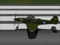
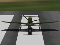
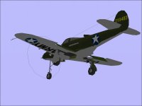
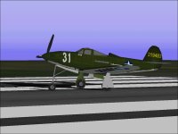
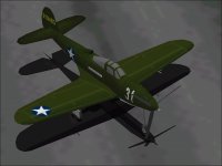
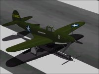
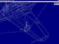
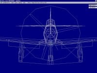
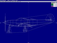
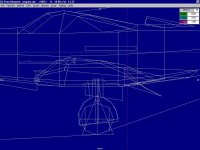
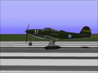
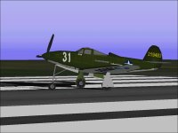
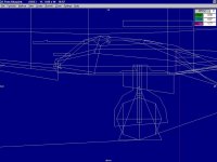
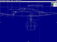
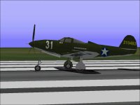
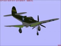
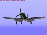
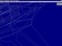
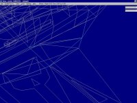
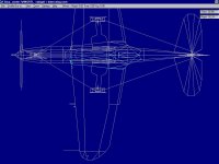
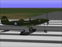
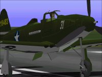
Attached are a few screenshots of Mr. Johnson's Airacobra as a starting point.
I believe the shapes are generally pretty good but there are quite a few issues with the details....

- Ivan.
 

Attachments

  • Original_1.jpg
    Original_1.jpg
    40.2 KB · Views: 1
  • Original_2.jpg
    Original_2.jpg
    38.9 KB · Views: 0
  • Original_3.jpg
    Original_3.jpg
    33.3 KB · Views: 0
The Original Purpose

The original reason I began modifying Eric Johnson's Airacobra was to have a project to work on that was of no consequence.
After working on a project for a while, it is a pleasant change of pace to look at something different and perhaps make a few improvements with no particular end result or an upload in mind. I am usually working on at least two or three projects concurrently to have the choice of something different to switch to if I should get stuck somewhere, but my own projects tend to have some kind of goal and refining one's own work can be difficult.
Working on another Designer's project is a better change of pace because the design practices are certain to be different and because of the different thinking, there will be some room for "improvement".

With the P-39DEJ, its origin as a FS5 model was certain to leave room for improvement.
It was a very low polygon model with a total AF99 Parts count of only 450 and although the shapes were good, the 0.10 feet resolution meant that the Parts would be fairly crude.
As a contrast, my current AF99 projects typically go to about 1100 Parts and the resolution of a FS 98 / CFS model is 0.01 feet. (Actually it is 1/512 Meter if one is working in SCASM code.)

My own preference is not to do extensive work on another designer's project for re-release because no matter how much work is done, it is still someone else's project for copyright reasons. I prefer to release my own work which is why the only aeroplane I have ever uploaded that I did not originally design was Richard Osborne's Me 109E.

Attached is a screenshot showing the result after an increase in overall size by 1.91% in overall dimensions, the replacement of the original Propeller and a 6 inch stretch of the Nose Gear Strut.

Even at this stage, it was fairly obvious from looking at the existing AFX that EVERYTHING would need to be modified to get the correct shapes and dimensions:
If the Overall Length and Wing Span are off by 2%, it is highly unlikely that every individual piece of the model is undersize by a CONSISTENT 2%. It is much more likely that the inaccuracy was the result of "measurements by eyeball" and that there is no consistency. This was confirmed by observing that the original Propeller was considerably oversized for diameter instead of 2% undersized.

With this in mind, I decided to retain the original shapes as much as possible and only make Detail changes and modifications to reduce Bleeds and to test ideas. This model would serve as a experimental subject to develop techniques and Parts construction ideas for a new Airacobra project.

- Ivan.
 

Attachments

  • AiracobraAttitude.jpg
    AiracobraAttitude.jpg
    46.7 KB · Views: 2
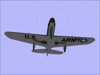
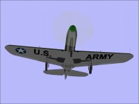
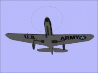
One of the things that bothered me about this particular aeroplane was that its markings were simply incorrect.

Early in the war, US aircraft had national insignia (stars) on both sides of the fuselage and on the top and bottom of both wings.
The star had a red circle in the middle. That circle was removed fairly early for obvious reasons.

A little later, the national insignia was painted on both sides of the fuselage but only on the top of the LEFT wing and the bottom of the RIGHT wing.
The idea was that it was natura for a gunner to aim between the dots (insignia) when shooting at an aeroplane and if th dots were only on one wing, it might mislead a gunner to aiming in the wrong place.

Note that the original paint job had the stars on the wrong side of each wing.
That was more tedious to correct than many of the actual corrections to the 3D model.

- Ivan.
 

Attachments

  • LittleShaver.jpg
    LittleShaver.jpg
    38.7 KB · Views: 0
  • P-39_RevisedMarkings.jpg
    P-39_RevisedMarkings.jpg
    45.8 KB · Views: 1
Design Limitations

The worst limitation of the original design tools used for this model in my opinion was the lack of precision in specifying vertex locations. 0.10 feet (1.2 inches) is a very large step. At times, I find that even 0.01 feet or roughly 1/8 inch is too large of a step to get Parts aligned the way I want.

I must commend Mr. Johnson on what he was able to accomplish with the tools he had. If I were working with the same tools, I would probably have built one rather ugly aeroplane and then given up in frustration. He managed to build quite a few nice looking designs.
The comments below will be fairly critical but in the context of working to the capabilities of Aircraft Factory 99 which is not the tool he had to use. My intent is not to disparage the quality of his work but more along the lines of explaining why this design has limitations when translated to AF99. I am also not saying he did not make mistakes, but then again, we all make mistakes.

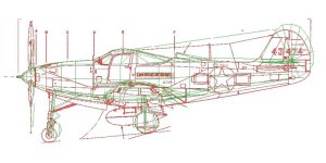
The first screenshot shows the Tail Structure.
As can be seen by the second image which is a comparison to a drawing by Paul Matt, the entire Tail is a bit too high in relation to the rest of the aeroplane.

The cross section at the Rudder Hinge Line on the Airacobra is very similar in appearance to an elongated Tear Drop. This is not difficult to represent in AF99 though in my own design I chose to simplify it slightly to save resources.
The cross section of the Rudder in this model is a thin Diamond.
It can be seen that the cross section of the Tail Cone is a very narrow Rectangle which doesn't really match the bottom of the Rudder but the difference on a textured model is difficult to see.
It can also be seen that the junction between the Fin and Tail Cone is a simple overlap of a triangular cross section.
The Tail Span is 13.0 feet while the actual measurement should be 13.50 feet
I believe the pieces are also a bit too thin.
If all these corrections are made, there is actually nothing at all remaining of the original pieces.

.......
 

Attachments

  • TailStructure.jpg
    TailStructure.jpg
    76.6 KB · Views: 1
  • P-39_Overlay_Compare2.jpg
    P-39_Overlay_Compare2.jpg
    59.6 KB · Views: 1
Design Limitations continued

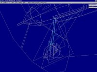
The strangest feature of this model is the inclusion of Plain Flaps instead of the correct Split Flaps.
This resulted in an arrangement of Wing panels designed around a disappearing Trailing Edge Flap section.
For Split flaps, this would not have been necessary.

As can be seen in the screenshot, each Wing is made up of only three top and bottom sections though there is also a flat Leading Edge Part included. The Wing Tip should be tapered upwards at the tip as was typical of American designs at the time and this is not represented. This feature might be very difficult to represent within 0.10 feet increments and this may be the reason it was not done.
The Wing Root Chord is actually quite close (about as close as it can be with 0.10 feet increments) but when I modified this model with a 1.91% stretch, this became a bit too large.

Although it is not apparent in the screenshot, there are concave sections in the Wing which should not be there.
At the Trailing Edge of the Wing Root, many polygons come together in close proximity but they really don't line up properly.
To correct all the issues would require a prety thorough rebuild but using the existing Parts as templates does not make sense because they are only accurate to at most 0.10 feet while AF99 can represent differences of 0.01 feet.

.......
 

Attachments

  • WingStructure.jpg
    WingStructure.jpg
    84 KB · Views: 2
Design Limitations Part 3

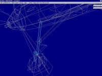
The most obvious indication of the low polygon limitations of this model is the 8 sided cross sections used in the Fuselage. Most of my current designs use 12 sided cross sections as a compromise between ideal shapes and resource limitations. They also typically use over twice the number of polygons that this model does.

In my opinion, the shapes are actually quite good though the angles between the Fuselage Parts are very noticeable.
Getting good drawings for the Airacobra can be quite difficult and there are indications that the drawings used as a reference were not the best because some of the proportions do not look quite right. I have run into the same problem with my early designs when the urge to build something quickly was a bit too strong.

The front view shows the 8 sided cross section and also shows a couple errors.
Note that the Nose Gear Doors are parallel while in reality the rear of each door should be further apart.
This becomes obvious when attempting to animate the parts and a very odd rotation line must be selected for the doors to meet properly.
Note also that the Inner Doors for the Main Gear are much too far inboard.

The side view shows the simplicity of the lines of the Fuselage.
What is visible but not obvious is that the belly section is made up of two Components that overlap the underside of the mid Fuselage. The two layers of polygons makes for an Assembly that tends to show intermittent bleeds that are very difficult (perhaps impossible) to eliminate entirely.

In removing the inner layer of polygons (those of the Fuselage), I found another minor discrepancy.
There is a gap between the Belly Components and Fuselage Components which is most noticeable in the front end and essentially forms a small scoop which is normally hidden by the similarity in textures.

.......
 

Attachments

  • CrossSection.jpg
    CrossSection.jpg
    66.3 KB · Views: 0
  • Profile.jpg
    Profile.jpg
    48.1 KB · Views: 0
Bad Attitude

As noted in the beginning, one of the aspects of this model that I had hoped to correct was the level attitude of the Fuselage when it was sitting at rest. Typically from drawings I have seen, the Fuselage under typical load conditions sits at slightly over a 6 degree nose-high attitude.

The Landing Gear should match.

The length of the Nose Gear Strut needed to be lengthened which is pretty obvious but what can also be seen in photographs is that the Main Gear Doors also appear to be slightly inclined when the aircraft is at rest.
If the Fuselage center line is inclined at 6 degrees, the Main Gear should be inclined about 7-8 degrees from the center line as well.

The screenshot shows (in Blue) what I believe the angle should actually be.
Note, however that this screenshot shows other problems as well.
Note that the Inner Main Gear Doors do not line up with the Wheel Wells.
This area should also have a small but very noticeable bump on the underside and be the deepest part of the Fuselage.
To make these corrections would require moving the separation lines between Components because quite a few pieces are not properly located.

- Ivan.
 

Attachments

  • MainGearPieces.jpg
    MainGearPieces.jpg
    67.8 KB · Views: 3
Accuracy versus Precision

Because of its origins as a FS 5 model, Every Vertex of Every Part in the entire original model was rounded off to the nearest 0.10 feet. If one thinks about it a little, that level of reproduction is quite crude and it is amazing that such a nice looking model was built with this limitation.
Representing a 34.00 feet Wing Span is pretty easy.
Representing a 30 feet 2 inch Length EXACTLY isn't really possible.
The choices are either 30.1 feet (30 feet 1.2 inches) or 30.2 feet (30 feet 2.4 inches).
While this is not too bad over the entire length of a 30 foot aeroplane, it gets to be rather interesting when every single Part (not polygon in this case) is done that way. It makes creating smooth curves rather difficult and representing precise measurements impossible.

Accuracy versus Precision:

Accuracy as used here is intended to mean the "Correctness" of measurements as compared to the actual aeroplane.
I spent a LOT of time gathering reference material and putting together the equivalent of construction jigs before actually creating any of the pieces for my version of the Airacobra. The Accuracy of my overall dimensions and critical measurements is around 0.01 inch to 0.10 inch. There are, however many many places where the exact measurements are not specified and the measurements are scaled from drawings of varying quality a few places where one has to put together a 3D representation from 2D drawings that don't really match each other.
A lot can be drawn on paper that can't actually be built in 3D. Think of the drawings by Maurits Escher.
In those places and when trying to "Connect the Dots", I figure the accuracy drops to about 0.5 inch.
In certain places, I chose to move pieces around to about 1.5 inches from where I knew they should be in order that the model could be built without exceeding the resources and abilities of Aircraft Factory 99.

We already know that the Accuracy of this original AFX was considerably less than that.
It is possible that the scaling factors were different with FS 5 and that was the reason for discrepancies but the proportions would then be more constant and they are not.

Precision as used here is intended to mean how closely a known dimension can be represented with the tools that are being used.
As described a few times before, there is a much greater limitation on Precision with the original model than with the AF 99 design tool we are using to modify it. The problem though is that with the original AFX as a starting point, the lack of Precision for FS 5 models becomes a limitation on the Accuracy of dimensions for the AF 99 model.

I had come to this conclusion very early in working with this model which is why I am convinced that an accurately dimensioned model cannot be built with this AFX as a starting point without replacing just about every single original Part at which point it makes more sense to start from scratch.

This is not to say that a very nice looking model cannot be built using this AFX to start, but it should be accepted that it will not accurately dimensioned unless the dimensions are checked at which point it becomes more tedious than building an entirely new model.

With this in mind, I decided very early on that I would not attempt to make major shape corrections except in places where it was very easy or in places where the original shape (Flaps and Propeller) really bothered me.
The Eight sided Fuselage would remain as would the oddly shaped Airfoils and Tail location.

.......
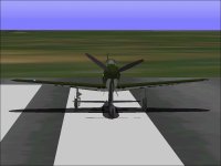
 
In hindsight, I probably should have been more willing to alter the shapes to eliminate concave spots, especially in the Wing Root area. (I may still do that if the shapes continue to bother me.)
At the time I began making modifications, Eric Johnson's Airacobra's only purpose for me was to serve as an experimental subject for trying out techniques to use on my new Airacobra.
The problem though is that I have a great aversion to leaving a project in a worse state than when I started so when I tested a modification, I completed it at least as far as needed to make it presentable. It just didn't seem right to leave a patient on the operating table with a procedure only half done.

.......
The first major change (which actually needed a new program to be written was to stretch all the pieces of the model to 1.0191 times the original dimension. This was a quick and dirty fix for Wing Span and Overall Length that were both too short.

This first change masked the fact that dimensions were to the nearest 0.10 feet because vertices no longer were even multiples of 0.10 feet. Seeing that the end of Stabilizer is 6.62 feet off the centerline is less obvious than seeing it at 6.50 feet from the centerline.
The accuracy obviously was not increased by doing this but was certainly slightly degraded because offsets of the vertices of each Part were now rounded to the nearest 0.01 feet after being multiplied by 1.0191. With some offsets rounding up and others rounding down, an error of 0.005 feet was introduced that wasnt there before but it is small enough to not be easily visible.
This is much like scanning a low resolution printout. The resulting image file may show a higher resolution than the original but what was introduced was noise and not real data.

The better approach (which I thought was too much effort to spend on a AFX that was not originally my own) would have been to determine where the inaccuracies were and make corrections where appropriate instead of stretching everything by a uniform 1.91%.

- Ivan.
 
Gun Modification

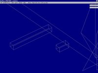
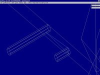
The Wing Guns's cross sections were modified many years ago.
The square cross section barrels did not seem appropriate considering the amount of resources remaining.
I believe the actual limitation was not because of resources but because of the 0.10 feet resolution.
These screenshots show the original and revised shapes.

I suppose square bullets might be useful if we were still fighting religious wars.

- Ivan.
 

Attachments

  • WingGuns_Original.jpg
    WingGuns_Original.jpg
    38.2 KB · Views: 0
  • WingGuns_Revised.jpg
    WingGuns_Revised.jpg
    46.7 KB · Views: 0
Beginning of the Current Round of Updates

The original Airacobra model had some unusual characteristics that I believed were not optimal.
There was almost no Glue (Viewing Plane) Parts in the Assembly and each Wing (outboard of the Wing Root) was made up of three sections.
There was a Flap section that changed depending on whether Flaps were retracted or deployed.
There was an Upper Wing Component and a Lower Wing Component.
This might have avoided some bleeds in the Flaps but caused a serious bleed between the Wing Fillet and Lower Wing Component when seen from outboard.

Fixing this involved replacing the upper and lower Wing with a single Component that also included Parts of the retracted Flaps. It wasn't quite as easy as it could be because there were Parts of the Wing that were concave and other Parts that were non-planar and I did not want to actually alter the original shapes. In hindsight I should have changed whatever was necessary to make the modifications easier, especially if those changes also improved the shape.

There are several other changes that were made between the two versions of the Airacobra shown in the screenshots and those changes will be described in the following posts.

- Ivan.
 

Attachments

  • WingFilletBleed.jpg
    WingFilletBleed.jpg
    40.5 KB · Views: 0
  • AiracobraAttitude.jpg
    AiracobraAttitude.jpg
    46.7 KB · Views: 0
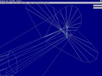
New Propeller

The Propeller was one of the areas that I believed that an update would greatly improve the appearance.

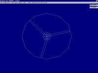
The original Propeller and Spinner is shown in the first screenshot.
What is not obvious is that each Part of the Propeller is created in a place that is not where it appears in the Assembly.
I believe that although this is possible, building in this way is not optimal because using Parts as references to create other Parts is not possible.

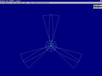
The updated Propeller pieces are shown in the second screenshot.
The Diameter has been corrected (reduced) and the Blade are aligned at Vertical and at 120 degree offsets.
I have no idea why a designer would intentionally misalign the Propeller Blades when creating them. To do so makes it very difficult to confirm that the blades have a correct angle or are planar.

As a side note, this propeller was created by comparing to photographs but the chord is actually a bit too narrow.
After building this propeller, I found the actual dimensions described in a manual, so my new build Airacobra project has the correct dimensions. Nearly nothing is shareable between the two models.

- Ivan.
 

Attachments

  • Propeller_Original.jpg
    Propeller_Original.jpg
    25.7 KB · Views: 0
  • Propeller_Revised.jpg
    Propeller_Revised.jpg
    29.7 KB · Views: 0
Replacment Pitot Tube

The original Pitot Tube simply did not look right.
Often concave sections in a Part or polygon simply will not display as they should.
Separating the pieces into different AF 99 Parts seems to solve the problem.
While doing this, I also chose to adjust the shape to more closely resemble the actual Pitot Tube that was used on the P-39.

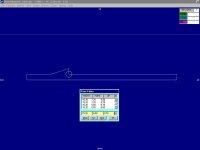
The first screenshot shows the Original Pitot Tube.
Note the coordinates listed for each vertex.
Note that they are even multiples of 0.10 feet.
When displayed in the simulator, the highlighted vertex seems to disappear.

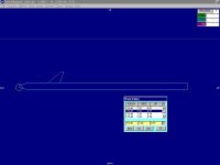
The second screenshot shows the Revised Pitot Tube.
Note that this is now two pieces and there are no concavities in either piece.
Note the coordinates are now specified to 0.01 feet.
This allows much greater refinement for shapes.

I was able to increase the height of the Pitot by 0.01 feet.
If the original designer wanted to increase the height, he would have had to double it.
Refining the shape did not involve any great skill on my part.
It was just a matter of using the tools that are available to me that were not available to the original designer.

- Ivan.
 

Attachments

  • Pitot_Original.jpg
    Pitot_Original.jpg
    26.7 KB · Views: 0
  • Pitot_Revised.jpg
    Pitot_Revised.jpg
    27 KB · Views: 0
Main Gear Doors

There was a similar problem with the Outer Doors on the Main Landing Gear.
One of the ways to confirm that the problem is one of concave Parts is to press the "Alt" key while in the simulator.
If the issue is a concave Part, it will disappear when this happens.

The first screenshot shows the single Part before editing.
The second screenshot shows the separated lower Part after editing.
The last screenshot shows the improved appearance in the simulator.
This is just a matter of making pieces appear as they were intended rather than making any actual shape changes.

- Ivan.
 

Attachments

  • GearDoor_Original.jpg
    GearDoor_Original.jpg
    58.1 KB · Views: 0
  • GearDoor_Revised.jpg
    GearDoor_Revised.jpg
    52.9 KB · Views: 0
  • P-39MainGearDoors.jpg
    P-39MainGearDoors.jpg
    44.9 KB · Views: 0
Updating the Flaps

I had replaced the Plain Flaps with Split Flaps quite a few years ago but had not made a great effort to do it particularly well. The latest revisions were done a bit better.

The first two screenshots show the deployed Flaps after modification.

The third and fourth screenshots show the Wing Root Trailing Edge with the Lower Wing Root Component highlighted.
Note that many of the Original panel lines do not actually meet and that the Upper and Lower Wing Roots do not actually match; The Trailing Edge does not look the same from the top and bottom views.

The panels meet properly in the Revised arrangement but do not reflect what the inboard edge of the Flap and Wing Trailing Edge should look like.

The fifth screenshot shows the top view of the center portion of the airframe with the Left Lower Wing Root (Belly) Component highlighted. This image shows why I chose to limit the corrections to this area to only those that were necessary to remove obvious visual problems.
A complete correction would have required that the entire underside of the Fuselage and Wing Root, Landing Gear, Flaps, Wheel Wells, Gear Doors, etc. be rebuilt.
The Trailing Edge of the Lower Wing Root is 2.10 feet from the Center Line which is also the inboard edge of the Flaps.
The actual aircraft has a Wing Center Section that extends to 22 inches from the aircraft Center Line.
22 inches would be 1.83333 feet from the Center Line but with FS 5 only 1.80 or 1.90 feet could be chosen.
In my opinion, this is the most complicated interaction of pieces in the whole model.

- Ivan.
 

Attachments

  • ReworkedFlaps1.jpg
    ReworkedFlaps1.jpg
    35.3 KB · Views: 1
  • ReworkedFlaps2.jpg
    ReworkedFlaps2.jpg
    32.2 KB · Views: 0
  • WingRoot_Original.jpg
    WingRoot_Original.jpg
    74.8 KB · Views: 0
  • WingRoot_Revised.jpg
    WingRoot_Revised.jpg
    85.2 KB · Views: 0
  • WingFilletDividingLine.jpg
    WingFilletDividingLine.jpg
    57.5 KB · Views: 0
Modified Nose Gear

The most obvious modification to the Nose Gear was to extend the strut by around 6 inches.
The Nose Gear Component also needed to be split into separate pieces to be animated properly.
With the original Component, the Brace would swing up and through the Nose during the retraction sequence.

The Gear Retraction of the Airacobra was VERY slow so there is plenty of time to watch this brace bleed through the Nose which appears quite silly.
The revised Component has the single arm of the brace replaced with two separate Parts which can be animated along a different axis. (There actually were a Pair of braces and not just a single piece.)
My new retraction animation sequence is not really correct but does not look quite as odd as a bar showing through the Nose panels.

Note that there are two other changes visible in these screenshots.
One of them is the altered Spinner and Motor Cannon shapes.

- Ivan.
 

Attachments

  • NoseGear_Original.jpg
    NoseGear_Original.jpg
    69.7 KB · Views: 0
  • NoseGear_Revised.jpg
    NoseGear_Revised.jpg
    73.3 KB · Views: 0
Main Gear Torque Links

Another correction that was done that I had forgotten to mention was correcting the solid Torque Links in the Main Landing Gear. This was yet another case of Concave Parts not displaying as intended.
The corrections can be see in the images of the updated Flaps.

- Ivan.
 

Attachments

  • P-39_TorqueLinks.jpg
    P-39_TorqueLinks.jpg
    41.3 KB · Views: 2
Main Gear Wells

On the original model, when viewed from the underside, the inboard part of the opposite side Main Gear Well would disappear as the viewpoint changed. It was a bit disconcerting to watch a piece that was in the foreground appear and disappear without anything obvious getting in the way.
The correction was fairly simple and should make some SCASM animation updates easier when it is time to to that.

The change in marking for the underside of the Wings can also be seen in these screenshots.

- Ivan.
 

Attachments

  • Missing_Right.jpg
    Missing_Right.jpg
    28 KB · Views: 0
  • Missing_Left.jpg
    Missing_Left.jpg
    29 KB · Views: 0
  • Missing_Neither.jpg
    Missing_Neither.jpg
    28 KB · Views: 0
Transparent Canopy

I had not originally intended to replace the solid canopy in the original model with a Canopy Frame and Transparent "Glass". It did not see worthwhile for a throw-away model that I was using just to test different assembly sequences.
When I saw the greatly improved appearance in Aleatorylamp's modified Airacobra, I decided to try adding Cockpit details to my modified version as well.

I also used this as an opportunity to build a low resource Pilot Figure that can be used on other models if the resource usage is too close to the limit.

- Ivan.
 

Attachments

  • NoGuts.jpg
    NoGuts.jpg
    49.1 KB · Views: 0
  • QuarterView.jpg
    QuarterView.jpg
    51.4 KB · Views: 0
Back
Top