Reworking Eric Johnson's Airacobra

Cockpit Details

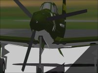
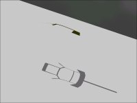
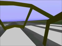
The first two screenshots show the Front Armour Plate in the solid cockpit and the equivalent pieces that are Parts of the Canopy Frame. These plates appear to block a lot of the forward view from the cockpit but in reality, the main instrument panel is directly behind the armour plate and visibility would not be improved without the armour.
A typical operationally equipped aircraft would also have a Reflector Gun Sight which would block even more of the view through the forward section of the windscreen.
The Gun Sight is not represented because it would be very resource intensive to build properly.

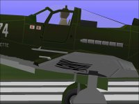
The view from the side shows the console and Control Panel, Pilot (of course), Seat Back, and Radio.
Note that the Seat Back is one of the few pieces that was taken from my new Airacobra and could be used after being shifted around a bit. Some references show what appears to be a Radio in this location. Some show this space as empty.

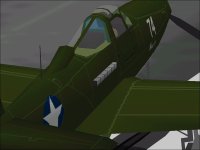
The view from aft shows the roll over structure and also shows the thick sheet of Armour Glass behind the Cockpit that was found in the early Airacobras. Late versions replaced the Armour Glass with a steel plate.

Texturing the Pilot was probably the most tedious work thus far.

The Control Panel and possbily two auxilliary Instrument Panels still need to be textured.

- Ivan.
 

Attachments

  • FrontArmourPlate_Original.jpg
    FrontArmourPlate_Original.jpg
    43.6 KB · Views: 0
  • FrontArmourPlate_Revised.jpg
    0 bytes · Views: 0
  • CockpitSideView.jpg
    CockpitSideView.jpg
    46.4 KB · Views: 0
  • Cockpit_View-From_Aft.jpg
    Cockpit_View-From_Aft.jpg
    36 KB · Views: 0
Reshaping the Spinner and Nose

The Overall Length of all production model of the P-39 / P-400 Airacobra is listed as 30 feet 2 inches.
Various drawings have different interpretations of where this dimension is measured from.
Obviously with different lengths of cannon barrel extending past the Spinner and with some aircraft not carrying a cannon at all (early in the production run), the length of the cannon barrel probably is not counted in the overall length.

My initial assumption based on a reference drawing that was otherwise very good was that the length was measured from the tip of the Spinner to the end of the Rudder.
The scaling facter of 1.0191 was chosen with this in mind to put this dimension at 30.16 feet.
30 feet 2 inches should convert to 30.166666 or 30.17 feet but I had a drawing that suggested that the actual overal length was about 1/16 inch shorter.

After reviewing other drawings, it appeared more likely that the forward reference point was not actually the Tip of the Spinner, but instead was an imaginary Datum line 3 inches in front of the Tip of the Spinner.
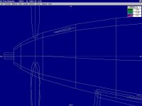
To adjust for this change, it made sense to shorten the Spinner slightly instead of modifying the entire model.
This was especially convenient because it also corrected the shape of the Spinner to flat as on the actual aircraft.

It also appeared to me that a single extra row of polygonsin the Nose would significantly improve the shape of the curves.

- Ivan.
 

Attachments

  • Spinner&Nose_Original.jpg
    Spinner&Nose_Original.jpg
    42.9 KB · Views: 0
  • Spinner&Nose_Revised.jpg
    Spinner&Nose_Revised.jpg
    46 KB · Views: 0
Flight Models

When I first started working on this model, the main purpose was to use it build a flight model for my P-39F.
For some reason it seems to help to have a reasonable looking visual model when developing a flight model.
There obviously isn't a logical connection except for locating a few reference points (which I didn't get exactly right in any case), but it still seems that way.

When Aleatorylamp released his modified EJ Airacobra, it occurred to me that my main reason for no choosing to build the original P-39D-BE was that it did not have a Fin Fillet but my working version of EJ's Airacobra didn't have one either.

As for actual differences in the Flight Models between the EJ test Airacobra and my own P-39F, they were fairly smal things such as Landing Gear contact points, Cockpit Viewpoints, Propeller Location and other little things to be found in mismatched models.

The only FUNCTIONAL difference between the P-39D and P-39F was the different manufacturer of the Propeller that was installed. The dimensions of the Propellers were the same but the minimum pitch of the Curtiss Electric Propeller installed in the P-39D was slightly higher than the Aeroproducts Propeller installed in the P-39F.
Curtis Electric - 21.5 - 51.5 Degrees
Aeroproducts - 20 - 55 Degrees

Does the 1.5 Degrees make any noticeable difference?
Probably not. Both Propeller are off their minimum pitch stops by the time the aircraft gets airborne at take-off.
With the way CFS handles interpolation, in THEORY, there should be a slight advantage to the Aeroproducts Propeller but I believe that it is entirely masked by other factors such as being able to steer a straight line during the take-off run because once airborne, there should be no differences at all above stall speed.

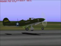
Attached are a couple screenhots from last night.
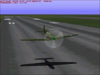
The first is a pretty typical landing flare at about 4 MPH above the stall.
No, I don't fly all that well, but this kind of thing is really pretty easy with the Airacobra.
The take-offs are a bit more interesting because of engine torque.

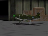
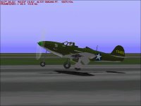
The second screenshot is after a long taxi test to test ground handling.
There were many better images when I was testing on my Game Machine, but I don't have enough software there to get a screenshot.

- Ivan.
 

Attachments

  • LandingFlare.jpg
    LandingFlare.jpg
    43.6 KB · Views: 0
  • Taxi_Test.jpg
    Taxi_Test.jpg
    37.8 KB · Views: 0
The Frame Underneath

In reworking this model, the choices have been to adjust or replace those things that were the most visually objectionable. For the most part, the shape looked pretty good in my opinion, so very minimal work was done there.

A couple nights ago, I decided to go after one of the things that had bothered me from the start.
The vertical center line of this model did not flow well.
In the simulator this issue wasn't even visible but it is the kind of thing I try to adjust on my own models.
I had not gone after it before because I wanted to leave the shapes close to original but after looking over the actual coordinates of the vertices, I got to thinking that the original designer WAS trying to keep a smooth curve but just didn't have the ability to locate points as well as I can with AF 99.

What should have been a 15 minute job ran about an hour and a half by the time I decided to rename a bunch of the Parts to make them easier to find and also only use Left side Parts and mirror them for the Right side. I had spent way too much time trying to figure out the naming convention before deciding to rename things in a manner that I could easily find them when I needed to.

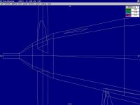
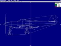
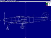
Attached are images of the Original Wireframe and the Modified Wireframe.
In some aspects it has changed a lot and in others, there have been nearly no changes other than re-scaling which is not visible.

- Ivan.
 

Attachments

  • Wireframe_Original.jpg
    Wireframe_Original.jpg
    48.2 KB · Views: 0
  • Wireframe_Modified.jpg
    Wireframe_Modified.jpg
    46.7 KB · Views: 0
More Cockpit Details

Over the last few days, I found that some of the pieces of the Cockpit needed to be adjusted.
They actually look fine from outside but from a Virtual Cockpit view, they were blocking too much of the vision to the rear. Because of those adjustments, other pieces need to be adjusted to fit and so on as usual.
This is really the reason for taking the time to work on modifying this model.
It gives me a chance to work out the bugs before implementing on my new build Airacobra.

I believe that the Instrument Panel also should be even higher than I have it now. In the real aeroplane, it appears to obscure most of the view of the nose from the cockpit.

The Canopy Frame for the Virtual Cockpit is also in the works and almost complete.
It just needs to be flipped inside out but I have a program for doing that with the SCASM code and it USUALLY works without a problem. Then, it is just a matter of extracting the single SCASM subroutine to combine with the rest of the SCASM model.

The Check List was completed yesterday. It should be nearly identical between the P-39D here and the P-39F.

- Ivan.
 
Status Update

The recent diversion to work on the P-47D-23 was actually very related to working on the flight model for the Airacobra.
Both have quite similar centers of gravity though quite different conditions.
The CoG is pretty far aft in the Thunderbolt when it is fully loaded but stability improves as fuel is burned from the aft fuel tank and is pretty good by the time all fuel and ammunition are expended.
The CoG is slightly further ahead on the Airacobra and moves rearward as stores are expended and the aircraft becomes increasingly unstable.

The last version of the AIR file I worked on several months ago (which I will call the "Version A") had a few intentional quirks and handled well but had rather conventional behaviour especially at the stall.
The updated version which I will call "Version B" incorporates some changes gained from experiments with the Thunderbolt and is much less stable and has some strange stall characteristics which seem to logically match some of the characteristics of the Airacobra.
There are some maneuvers I still cannot reproduce such as the infamous "Tumble".
There are some handling characteristics such as the very sensitive elevators that I have chosen to ignore in order to make the models more easily flyable in the simulator and I suspect that might also be preventing the Tumble.

Along with edits to the AIR file, there have been some minor edits to the model.
In this screenshot, the narrowed interior frame of the canopy can be seen.
It was modified so that the Virtual Cockpit view would have smaller obstructions.

- Ivan.
 

Attachments

  • P39DEJ_AfterTestFlight.jpg
    P39DEJ_AfterTestFlight.jpg
    42.3 KB · Views: 2
Minor Change in Plans

My original plan was to change nothing as far as textures and mapping that was not directly related to model changes.
The main reason was to be able to use existing texture sets on the new model with minimal modifications.
The second reason was to limit the changes because as with any model that we did not design, there are an endless list of things that can be "improved".
The third reason is that I simply hate texture mapping and working on new textures.

There are, however, certain things I just can't tolerate and I came across such a situation.
Different parts should not map to the same areas of the same texture files.
When this is done, it becomes impossible to paint one piece with a unique marking without affecting the other pieces which share the same texture; If I paint one wing tip red, I don't want to see a red pattern appear on the tail or some other piece of the aeroplane.

In this case, the Landing Gear covers mapped to the same areas.
With the standard Army Air Corps paint schemes, the underside is mostly a single colour, so it is not an obvious problem.
Stripes and certain camouflage pattern simply could not be done.
The texture remapping was completed earlier today and I also finished applying a texture to the last piece that I believe needed one: the Control Panel.

The screenshot shows the new Control Panel. There is no point showing the Landing Gear because the appearance has not changed.

- Ivan.
 

Attachments

  • Airacobra_Instruments.jpg
    Airacobra_Instruments.jpg
    48.4 KB · Views: 2
Interior Canopy Frame

One of the pieces that needs to be added via SCASM is the interior of the Canopy Frame.
The process I use is to first build it as a single AF99 Component and texture it with an interior colour.
When it is textured, it will still show all polygons on the outside as is typical with Components marked as "Smooth".
After it is built, I disassemble with MdlDisAs into SCASM code and flip the polygons outside-in with a program I wrote a couple years ago.
This process seems to work most of the time but in the past I have had some very strange blow ups.
These days, I am tending to believe that the blow ups were a result of my malfunctioning Development Computer before it finally died.

Attached are screenshots showing the appearance at each stage.
The Reversed "Outside-In" model is quite odd to flip around in the simulator.

- Ivan.
 

Attachments

  • CFrame_Isolated.jpg
    CFrame_Isolated.jpg
    22.7 KB · Views: 0
  • CFrame_Flipped.jpg
    CFrame_Flipped.jpg
    18.6 KB · Views: 0
  • CFrane_Inside.jpg
    CFrane_Inside.jpg
    38.5 KB · Views: 0
Airacobra Instrument Panel

Hello All,

The Virtual Cockpit and SCASM edits were done not long after the prior post.
I had not realised that I didn't post any screenshots.

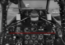
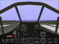
The first attached image show what an actual cockpit view from the Airacobra looks like.
To maintain the aspect ratio of the CFS panel, the last two rows of gauges could not be included.

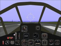
The second image is a screenshot of my new Airacobra Panel background with gauges.
Note that the arrangement of gauges in the CFS panel is only meant to give an impression of the actual instrument panel.
In the actual aircraft, the instrument panel is very narrow but very high and there are controls tucked into various corners of the cockpit. (The Starter is a pedal on the cockpit floor.) There are also instruments that have no equivalent. (Gauges for the propeller reduction gear, etc.)

The center panel is mostly correct with the exception that the compass is replaced by a clock. There is no point in having both a Compass and a Directional Gyro in CFS.
The right panel contains engine gauges as on the actual aircraft.
The left panel is an assortment of gauges that have no other place.

Improved versions of some gauges are already in the works and I can see quite a few places where the background can be improved.

- Ivan.
 

Attachments

  • P-39Cockpit.jpg
    P-39Cockpit.jpg
    48.6 KB · Views: 0
  • Airacobra_Panel.jpg
    Airacobra_Panel.jpg
    72.9 KB · Views: 0
New Gauges for Airacobra

Some folks may have noticed that in the last panel screenshot that the Trim Gauge looked a bit odd.
It resembles the stock SP.Trim Gauge in appearance and general function but is actually a replacement that I programmed a few years back. I wanted a gauge that was a bit easier to read and in which the markings actually had some meaning.
In the replacement version, the tick marks each represent 10 notches of trim.

The first gauge I chose to replace specifically for this project was the Fuel Selector.
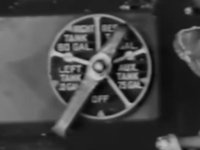
The appearance of the actual P-39 Airacobra Fuel Selector is shown in the first attached image.
Note that it has 5 positions.
The selector is currently set at the "Reserve" Tank. Going Counter Clockwise, we have
Right Main Tank
Left Main Tank
Off
Auxiliary Tank (Drop Tank)
Reserve Tank

The P-39 had two internal fuel tanks of 60 US Gallons (at most) with one installed in each inner wing section for a total of 120 Gallons. Some models had even smaller fuel tanks (notably the P-39N) for a total of only 87 Gallons.
The "Reserve" tank was actually just a standpipe reserve and part of the Left Wing Tank.
In other words, selecting "Left Main" would draw only the top 40 Gallons of Fuel and leave the last 20 Gallons as "Reserve".
Selecting "Reserve" would draw from the Left Wing Tank until it was empty.

Although it is possible to implement this in CFS (I believe), I chose to implement the simpler case of just simple Left and Right Main Tanks. Getting too complicated on the first try is generally not a great idea.
The problem is that there are no stock Fuel Selectors that only have Left and Right Tanks, so I programmed one based in general appearance on the stock P51D Fuel Selector but without the Center Tank.

The second image shows the new gauge installed in the panel.

The gauge is done as a FS98 Gauge to avoid the Multi Gauge complications and because there isn't an obvious second gauge I should combine with it. Unfortunately it requires the Render3D setting to be off in order to work.
I believe there will need to be an updated version as a FS2000 / CFS style Multi Gauge to allow access to Fuel Tanks that are not visible in the FS98 SDK.

I also made a change to the tick marks on the Trim Gauge but it seems to me that the original version was better.

- Ivan.
 

Attachments

  • AiracobraPanel2.jpg
    AiracobraPanel2.jpg
    73.3 KB · Views: 0
  • FuelSelector.jpg
    FuelSelector.jpg
    31.4 KB · Views: 0
Hi Ivan, I am curious to know if your plane will also have a VC with working gauges.

Regards,

Erik Hertzberger (hertzie).
 
Hello Hertzie,

First of all, I can't really call this "MY" Plane. It is still Eric Johnson's P-39 though of course the modifications are mine.

I have never really been interested in getting working gauges in a Virtual Cockpit. I don't see the reward as being worth the effort.
If I were to actually try putting working gauges into the VC, I would start off with a better model or at least one that I owned.
As I stated a few times before, this particular project has so many things wrong with it that can't really be cured without a total rebuild and since it didn't start as my project, I am not inclined to spend the kind of effort needed to put things right.

I am basically using this project to aid in development for my own version of the Airacobra.

My Apologies.
- Ivan.
 
Hello All,

I had intended to create a new Fuel Gauge before releasing this project but am finding that creating the bitmaps for the gauge is taking much longer than I had expected. The bitmaps are not really that complicated but they do tend to be tedious.
I do intend to complete the fuel gauge at some point, but improvement would be one of appearance rather than functionality.

The project was uploading this evening and hopefully will be available soon.
Let me know what you think of the results of this rather long diversion of a project.

- Ivan.
 

Attachments

  • FlightLine.jpg
    FlightLine.jpg
    57.7 KB · Views: 1
The new aeroplane was approved very early this morning (about 2.5 hours after upload) and can be found here:
http://www.sim-outhouse.com/sohforums/local_links.php?catid=19&linkid=25234

I should have added this to the description:
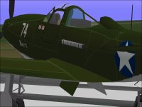
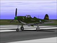
The markings are intended as a tribute to Number 74 "Nanette" flown by Edwards Park in New Guinea.
The exact markings are not well documented so they are done in the typical style of aircraft in that theatre and are a guess.

"Nanette: Her Pilot's Love Story" was a book written as "an exaggeration" by Mr. Park and published in 1977.
It was quite a good book which I remember reading when I was young.

- Ivan.
 

Attachments

  • NanetteBook.jpg
    NanetteBook.jpg
    33.9 KB · Views: 0
  • Nanette1.jpg
    Nanette1.jpg
    27.5 KB · Views: 0
Minor Update

Project has been updated with a CFS Style Multi Gauge Fuel Selector to improve Cockpit Interior View.
It seems a bit silly to have a single gauge inside a Multi Gauge package but that is how CFS / FS 2000 does things.

This should eliminate the black bar at the bottom of some of the interior views.

- Ivan.
 
Center of Gravity

Even though the Airacobra was released a few months ago, I was never quite satisfied with how things turned out.
It seemed that the aircraft didn't handle quite as well as it should have. For a while I was trying to find the cause.
I don't know for sure that I have found the actual problem but a very slight modification to the Center of Gravity seems to have improved the handling much more than I expected.

Time for some more testing and fine tuning.

- Ivan.
 

Attachments

  • Nanette_TestFlying.jpg
    Nanette_TestFlying.jpg
    49.2 KB · Views: 0
  • Nanette_LowPass.jpg
    Nanette_LowPass.jpg
    45.3 KB · Views: 0
  • Nanette_TestingFinished.jpg
    Nanette_TestingFinished.jpg
    40.7 KB · Views: 0
P-39dej_052

After a couple months of testing, fine tuning, and other projects, the updated version of Eric Johnson's Airacobra was just uploaded.
The most significant change was a 1 inch shift of the Airframe CoG Aft and this appears to have fixed most of the handling problems.
Visual model was not updated for the CoG shift.

The Airacobra now behaves fairly well when fully loaded and is quite agile.
It should be flown smoothly without abrupt control movements and speed should be kept as high as possible.
When the ammunition is expended, stability is very poor and stalls are to be avoided.

It is actually very easy to land as long as one remembers that the Airacobra is a heavy aeroplane and falls out of the sky at about 95 MPH and gets directionally unstable at the stall. Keep a little margin of speed!

- Ivan.
 

Attachments

  • FlyPast.jpg
    FlyPast.jpg
    43.8 KB · Views: 1
P-39dej_053

Up to this point, I had been mostly concerned with Flight Performance and never really looked very hard at the Damage Profile except where it might affect performance.
Recently, a slight diversion with the P-39C version of the Airacobra called my attention to how BAD the current DP file was for the P-39D.
The differences between the C and D models was a bit less armament and a LOT less armour. The armament was pretty easy to change but when I started editing the Damage values to address the lack of armour, I found that pretty much none of the pieces in the damage boxes actually lined up with where the parts were in the real aircraft. The existing DP also made the Airacobra a much tougher aircraft than it should have been.

From what I can tell now, the DP file was a modified copy of the stock FW 190A which was an amazingly tough and compact little fighter.
One of the side effects of this origin was that it didn't have a coolant radiator / reservoir even though the Airacobra has a liquid cooled engine.

From a weight and performance standpoint, nothing has changed. Folks who choose to fly it in combat will notice that the 37 mm cannon now hits harder as it should considering the shell is over a pound and a quarter in weight and the wing guns are better harmonized (330 Yards), and of course that the pieces now match their actual location inside the aeroplane.

The existing library entry has been updated.

- Ivan.
 
One of the reasons I chose to remap as few textures as possible when reworking this model from the original was so that it could host other paint schemes that had been developed for the original model by Eric Johnson. That this can be done VERY easily has been shown by the adaptation of the paint scheme used for the P-39CEJ that was recently uploaded.
Another very nice paint scheme which I may try to adapt may be found in the download section here:

http://www.sim-outhouse.com/sohforums/local_links.php?action=jump&catid=19&id=13835

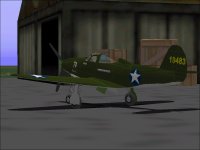
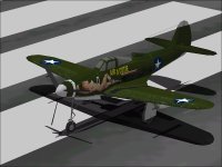
I believe the original artist may be arfyhun. I found this morning that I already had the package on my Development Computer but had just never installed it. Attached is a screenshot from the simulator of the installed aeroplane.

From the download description, the two models of Airacobra which wore these markings were a P-39D and P-39N. Interestingly, the download is labeled P-39F. The model however is a P-39Q with underwing gun pods which were never installed in either the D or the N model Airacobra. Except for the lack of a fin fillet, my updated model would make a much better canvas though I would also take some liberties in applying the paint job. The current flight model is also a much better match than the one from the package which is much too agile for an Airacobra. Its roll rate would be competitive with an Pitts Special and certainly leave either a P-40 or a FW 190 behind.

- Ivan.
 

Attachments

  • AirACutie.jpg
    AirACutie.jpg
    55.1 KB · Views: 1
Cute Can of Worms

In poking around with the "Air A Cutie", I came across a few more problems than I had expected.
First of all, although there was a comment that there were paintings on BOTH sides of the fuselage, the CFS model only has an image on one side; the starboard side is blank.
In a quick search for photographs of the starboard side of Air A Cutie (The two paintings are not the same), I found that the general consensus among model builders (The ultimate rivet-counters) was that "Air A Cutie" wasn't actually a P-39D-1 but was a P-400 or a British contract Airacobra Mk.I that was taken over by the US Army and used in New Guinea.... Also by 8 FG, 36 FS in 1943. Perhaps there was a THIRD aircraft that wasn't mentioned in the download? Serial number was AP287.

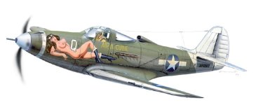
Attached is an image from a modelling guide.

If this aircraft really was a P-400 armed with a Hispano 20mm cannon instead of the 37mm, then the visual model should have a long skinny barrel sticking out of the spinner instead of the short little 37mm blast tube.
Perhaps this would be a good opportunity to replace the cannon barrel with the 20mm version via SCASM?

- Ivan.
 

Attachments

  • Air-A-Cutie.jpg
    Air-A-Cutie.jpg
    32.2 KB · Views: 1
Back
Top