• There seems to be an uptick in Political comments in recent months. Those of us who are long time members of the site know that Political and Religious content has been banned for years. Nothing has changed. Please leave all political and religious comments out of the forums.

    If you recently joined the forums you were not presented with this restriction in the terms of service. This was due to a conversion error when we went from vBulletin to Xenforo. We have updated our terms of service to reflect these corrections.

    Please note any post refering to a politician will be considered political even if it is intended to be humor. Our experience is these topics have a way of dividing the forums and causing deep resentment among members. It is a poison to the community. We appreciate compliance with the rules.

    The Staff of SOH

  • Please see the most recent updates in the "Where did the .com name go?" thread. Posts number 16 and 17.

    Post 16 Update

    Post 17 Warning

A new tool in MCX is ideal for painters/re-painters in any sim!

Tako_Kichi

Administrator
Staff member
Many aircraft painters/re-painters for multiple flight simulators often find themselves in need of 'texture maps' in order to know where parts are laid out on the texture sheet. If you are lucky the developer will provide end users with a paint-kit that ideally includes the mapping layers so that painters/re-painters know exactly where the parts are and consequently where to apply their artwork.

Sometimes developers omit the mapping layers in their paint-kits for some reason and painters/re-painters have to resort to trial and error to find out where parts are, where the gaps between the parts are to prevent bleed over and where mapping features are located in order to align various parts of the artwork.

In the worst case scenario the developer will supply no paint-kit at all and simply provides a plain white texture for the aircraft and then expects end users to jump through hoops trying to get the various 'blending modes' in art programs like Photoshop and Paintshop Pro to display the required artwork (you know who you are Carenado and others)! This is always a hit and miss process and takes hours of extra time when the job could be done easily with a proper texture map in a proper paint-kit!

A Solution is at Hand!

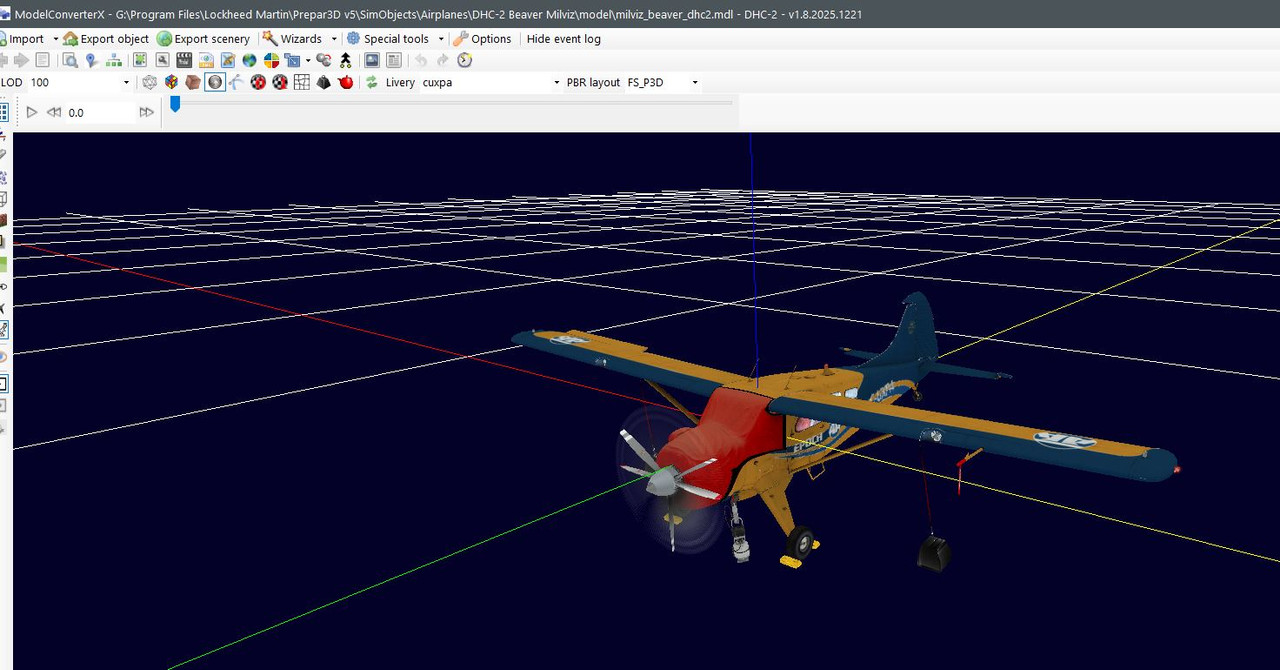
One of the tools that has been available to painters/re-painters and developers for many years is the utility known as 'Model Converter X' (MCX) which was created by 'Arno' and is available from the FSDeveloper website.

Recently 'Arno' has introduced a new feature to the tool that allows users to save the mapping directly from the model to a texture file so that even if no mapping layer is provided in the paint-kit or only a white texture is provided users can access all of the mapping to make re-painting easier!

The new feature is currently only available in the 'Development Release' but it is well worth the time for painters/re-painters to go and get the development version so that they can access the power of this new feature as it really is a massive help when painting/re-painting textures.

Here are a few images to whet your appetites:

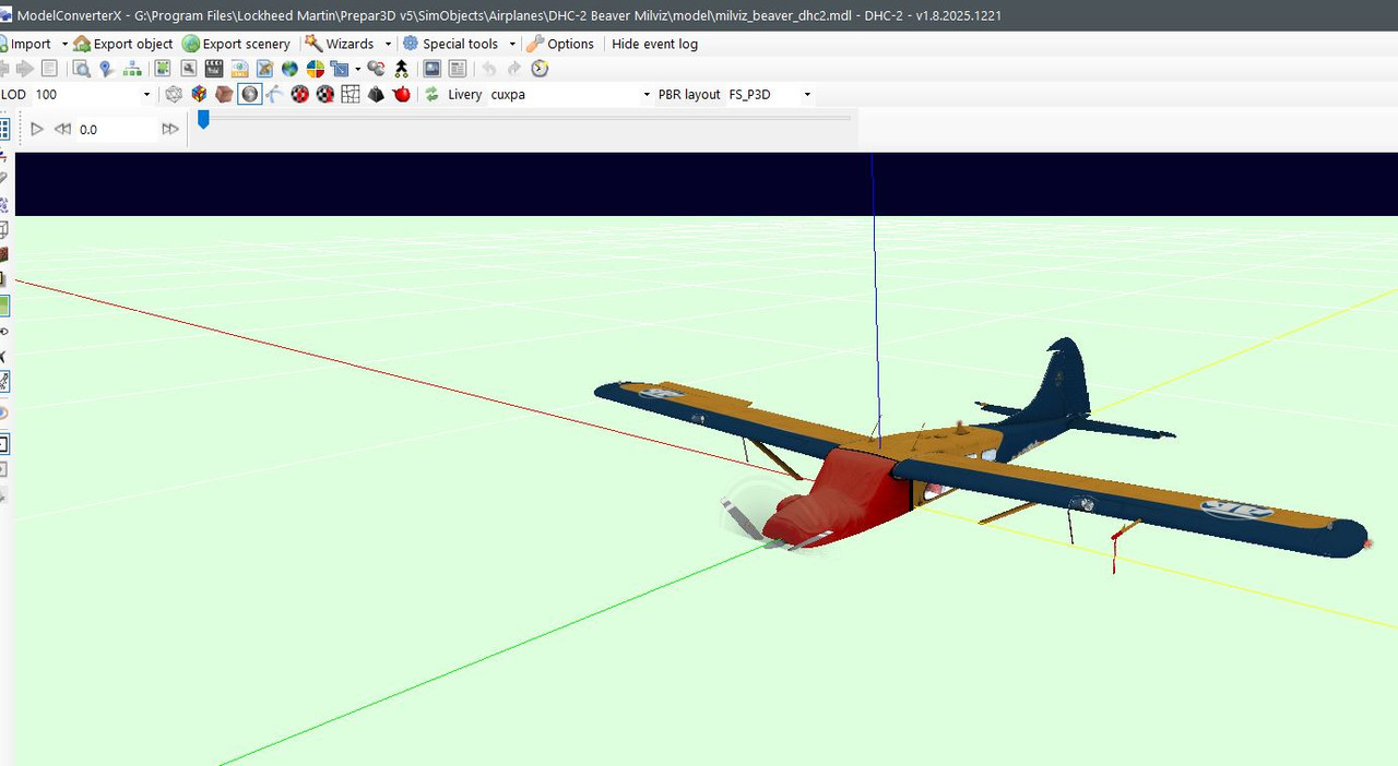
First up we have the texture map pulled from a regular texture sheet and showing the mesh against a plain background. The line width and edge color can be selected/changed to suit your needs as required.

6-edges shown.jpg

If you prefer you can use the 'Render polygons' option to fill in the polygons with a color of your choice and change the background colour too if required, like so:

8-polygons shown.jpg

You can even 'blend' the mesh back onto the original texture sheet if required:

11-blended texture.jpg

The default texture map size is identical to the original texture sheet but you can change this to suit your requirements by using the 'Overwrite texture size' controls. Make sure the 'Overwrite texture size' box is checked and then enter the dimensions you need for the resulting texture map. In this case I chose 2048 x 2048 as an example.

When you are happy with all of your changes you can save the file to a location of your choice and in many of the common texture formats available.

Conclusion

Hopefully this brief announcement will help you create texture mapping sheets for the aircraft that don't have full paint-kits or that don't have paint-kits at all (I'm looking at you again Carenado!)

Thanks again are due to 'Arno' from FSDeveloper for providing the amazing MCX in the first place and also for constantly updating it with new features for the developer and re-painter communities.

I have attached a PDF tutorial that will go through the steps of obtaining the Development Version of MCX and any additional utilities required and give examples of how to install and use it.

Happy painting! (y)
 

Attachments

  • MCX Texture Map Manual.pdf
    1,009.6 KB · Views: 11
When I open a mdl with MCX, the aircraft is below ground level unless I turn off the green ground and even then, it appears below the grid lines unless I use the move option and elevate it above ground. From what I've read at FSDeveloper, they say this is normal. If I use the snap to ground and ignore the Z box it will be way above ground. So what is the solution to make the model display AT ground lever the first time?
Capture.jpg


Capture1.jpg
 
There is no such thing as 'at ground level' when you open a model in MCX.

The first image you posted is absolutely correct and the white grid lines and red, green and blue axis lines all emanate from the model's 'Point of Origin' (0,0,0) which is an arbitrary point specified by the model maker. In theory it could be anywhere on the model (or even away from the model in space somewhere) but is a generally accepted 'standard' that the green line should align with the middle of the fuselage when looking from the top (Plan View), the red line is then perpendicular to the green line (horizontally) and is positioned at a point that is 1/4 or 25% of the way back from the leading edge of the wing (sometimes known as the 1/4 chord position) and the blue line is perpendicular to both the red and green lines in the vertical plane and all three lines share the exact same intersection point.

The next important fact is how far up the fuselage (vertically) the Point of Origin sits. There are two trains of thought here, one is that it should pass through the centre of the prop spinner on propeller aircraft or the centre of the turbine in jet aircraft (essentially through the centre of thrust). The other view is that it should go through the middle of the fuselage/nose when viewed from the side much like the green line does when viewed from the top. I just checked 5 randomly picked aircraft in my current hangar in P3D and in 4 cases the Point of Origin runs through the middle of the engine/spinner/turbine and only Manfred Jahn's DC3/C-47 had the Point of Origin in the middle of the nose when viewed from the side.

It makes no difference where on the model it sits as it just acts as the reference point from which ALL dimensions on the model are taken but it makes sense to have it close to the centre of gravity and the centre of thrust to make calculations easier and more logical.

This is the reason why 'taildraggers' (like in your example) appear in MCX as if they are flying and not sitting with the three wheels on the ground and it's because there is no 'ground' per se and the aircraft is sitting in alignment with the fore/aft, left/right and up/down axes from the Point of Origin.
When I say "ground level" and I think you know what I'm referring to is, the wheels of the aircraft are touching the ground and all along, I thought
that MCX would display any aircraft model with wheels touching the ground and not like it is currently doing. If I use the model elevate option,
the wheels of the aircraft are at or above ground level which IMHO presents my having to guestimate the correct elevation where the wheels
are at the optimum contact with the ground. The "Snap to ground" option ( and ignore "Z") will sometime display the model with wheels in perfect
contact with the ground hence a guess as to correct elevation so as to view the entire aircraft. I read your explanation of Point of Origin but it just
has not "sunk in" my mind as to why I have to make elevation adjustments to see the aircraft model display above the grid lines. I suppose I could just turn off the grid lines and the green grass option and I would see the whole model without any reference points and the illusion that the plane
has sunk below ground. Thanks anyway for your replies on this matter.
 
When I say "ground level" and I think you know what I'm referring to is, the wheels of the aircraft are touching the ground and all along, I thought
that MCX would display any aircraft model with wheels touching the ground and not like it is currently doing. If I use the model elevate option,
the wheels of the aircraft are at or above ground level which IMHO presents my having to guestimate the correct elevation where the wheels
are at the optimum contact with the ground. The "Snap to ground" option ( and ignore "Z") will sometime display the model with wheels in perfect
contact with the ground hence a guess as to correct elevation so as to view the entire aircraft.
MCX displays the model aligned to the Point of Origin in a three dimensional 'space'. It does not care where the ground is as it's only purpose is to display the selected model file (.mdl) and not it's assumed surroundings. MCX cannot automatically display an aircraft with it's wheels touching some 'imaginary' ground plane because it is just reading the data from the model file and cannot account for the fuel in the tanks and the weight of the passengers/crew/baggage/cargo etc. which act to compress the oleo struts by varying amounts and therefore change the distance from the imaginary ground plane to the Point of Origin which is where all dimension are taken from. In addition, when MCX loads a model the animations are all at the zero animation frames position and in the case of undercarriage animations that means with the gear up in aircraft with retracting gear and with the suspension fully extended in the case of fixed gear aircraft. So, again, it cannot automatically put the aircraft onto some imaginary ground surface if the gear is either up or fully extended.
I read your explanation of Point of Origin but it just
has not "sunk in" my mind as to why I have to make elevation adjustments to see the aircraft model display above the grid lines.
The aircraft does not need to be 'above the grid lines'! The grid lines emanate from the Point of Origin which is the vital concept that you are missing at the moment. At no point was MCX meant to show a model of any aircraft (or any other model type come to that) in reference to some imaginary landscape surface.
I suppose I could just turn off the grid lines and the green grass option and I would see the whole model without any reference points and the illusion that the plane
has sunk below ground. Thanks anyway for your replies on this matter.
You are only seeing an 'illusion' of the plane being sunk into the ground because your mind is seeing the grid lines as a flat and solid surface which is incorrect, there is no 'ground', never was, never will be. It's just a model floating in 3D space!
 
MCX displays the model aligned to the Point of Origin in a three dimensional 'space'. It does not care where the ground is as it's only purpose is to display the selected model file (.mdl) and not it's assumed surroundings. MCX cannot automatically display an aircraft with it's wheels touching some 'imaginary' ground plane because it is just reading the data from the model file and cannot account for the fuel in the tanks and the weight of the passengers/crew/baggage/cargo etc. which act to compress the oleo struts by varying amounts and therefore change the distance from the imaginary ground plane to the Point of Origin which is where all dimension are taken from. In addition, when MCX loads a model the animations are all at the zero animation frames position and in the case of undercarriage animations that means with the gear up in aircraft with retracting gear and with the suspension fully extended in the case of fixed gear aircraft. So, again, it cannot automatically put the aircraft onto some imaginary ground surface if the gear is either up or fully extended.

The aircraft does not need to be 'above the grid lines'! The grid lines emanate from the Point of Origin which is the vital concept that you are missing at the moment. At no point was MCX meant to show a model of any aircraft (or any other model type come to that) in reference to some imaginary landscape surface.

You are only seeing an 'illusion' of the plane being sunk into the ground because your mind is seeing the grid lines as a flat and solid surface which is incorrect, there is no 'ground', never was, never will be. It's just a model floating in 3D space!
Thank you kindly sir for your in depth explanation. I appreciate it and now understand what you have said. Thanks for bringing to light those factors I was unaware of. I would like to ask about the move option in MCX, I know if I want to see the model appear above the grid lines, I can use the move model option so that it will be fully visible above the grid lines.
 
Last edited:
There was a time when I was placing static aircraft in a scenery for P3DV5 and lo and behold, the static aircraft looked like the landing gears were down (landing gears were below runway). I went to FSDeveloper and asked about this issue and was told that I would have to elevate the static aircraft using MCX and the elevate option (which was new to me) and was a trial and error method until the tires of the Static Aircraft were spot on contact with pavement.
 
There was a time when I was placing static aircraft in a scenery for P3DV5 and lo and behold, the static aircraft looked like the landing gears were down (landing gears were below runway). I went to FSDeveloper and asked about this issue and was told that I would have to elevate the static aircraft using MCX and the elevate option (which was new to me) and was a trial and error method until the tires of the Static Aircraft were spot on contact with pavement.
That is a different procedure where you are moving the 'PoO' on a flyable object in order for it to be used as a static object. That is not the 'normal' way of displaying aircraft in MCX.
 
PoO = Point of Origin shorthand to save typing it out all the time. It's the place where ALL measurements on the model are taken from.
 
Back
Top