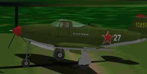
Analysing and modifying the AFX file with QBasic.

Hello Aleatorylamp,

Aleatorylamp said:
The Spinner in the Paul Matt drawings is 1.38 ft long.

The measurements I am getting from my version of Paul Matt's P-39Q drawing are a little different.
There is a noticeable gap between the back of the Spinner and the Fuselage.
I am getting 1.35 feet to the back of the Spinner and 1.42 feet to the joint at the Fuselage.
This is one of the strange parts of this drawing.
I have never seen another like it and photographs and films do not show this gap.

Aleatorylamp said:
Initially I (we) scaled the length to 30.16 ft from spinner to tip, and that has now changed to 29.92, or 29.91 ft. In my case I have the spinner tip at the same position as you do, and the rearmost point at just 0.01 ft more.


Keep in mind that we are discussing rounding errors here.
30 feet 2 inches = 30.16666666 feet which I initially rounded to 30.17 feet.
From looking at other drawings, I believe that the actual object was about 1/16 inch shorter which is why I rounded it down to 30.16 feet.
Now the difference between the Datum and the Spinner Tip is 3 inches or 0.25 feet thus 30.16 - 0.25 = 29.91 feet.
Of course if you start from 30 feet 2 inches - 3 inches = 29 feet 11 inches = 29.91666666 feet, you might round differently.
I made a choice based on what information I had.
The relevant drawings are all in the Airacobra thread.

Aleatorylamp said:
After re-scaling the model with the QBasic Modifier, if one were to re-scale the drawings, all the elements of the plane would by logic perfectly fit the new drawings, so the re-building work I have done is not wasted by any means. I don´t know how this could be different.

Incidentally, as vertical and horizontal scales on the drawings are the same, the height also has to be scaled down, otherwise shapes distort. I hadn´t got round to that yet, but I´ve just done it, and the wheels are perfectly round, which is a good indicator. The topmost canopy height went down by 0.03 ft, so it was necessary to do this.


I guess the difference here is that you are working entirely from proportions from drawings and I am throwing in actual measurements from the aeroplane whenever I can.
As an example, the Propeller Diameter of my AeroProp is 10 feet 4.5 inches or 10.375 feet.
This is rounded to 10.38 feet in the model. (An even number is good because it is really the Radius we will be using and not the Diameter.)
Radius would be 5.19 feet
As soon as we go through your multiplier, the new Radius would be 5.19 * 0.991932 = 5.14812708 which rounds to 5.15 feet.
My Propeller just lost about 1/2 inch off the Tip of each Blade!

Regarding AIR files:
I tried to pull some dimensions from the Monografie drawings and use them in the AIR file and that was a mistake.
The scaled dimensions do not agree with the documented dimensions, so I am going with what I can infer from the documented values.
I will need to undo most of what I put in at some point.

- Ivan.
 
Hello Ivan,
The best would be to visit a museum and take along a tape-measure...
The rounding off of plus or minus 0.01 ft is not really so important to me, so that will be fine! Thanks for explaining it, though.

Any drawing has to be scaled, and that will give the proportions if you need them, mainly to be able to check if they coincide with reality, or what one supposes is reality! You have to start off with some tangible piece of data though, and if that varies, then you have to re-scale the drawings and the model. One advantage of Paul Matt´s drawings is thankfully that you don´t need a different scale for the wingspan as for the fuselage.

Update - added paragraph:
I don´t know why I wrote that - it must have been the headache, because it´s not true: the fuselage/wingspan proportion is not 0.88, so the scale for the wingspan is different.
I have at least four different sets of drawings, with different fuselage/wingspan proportions: 0.867, 0.0882, 0.8917 and 0.8995.
The first two are by Paul Matt, and have different proportions - one of them is a bit close to your Polish drawings.

This has happened to me on other aircraft drawings, with the result that you don´t really know which of the two scales then applies to the height. Usually it´s the same as the length, but not always. Sometimes it´s not even the scale on the wingspan drawings, and then you can only compare from photos.


I got the propeller diameter measurement from the diagram on your Airacobra thread, which was very close to what I had been supposing.
Now that you mention it, I still have to check that all the blades have the same measurement after the vertical re-scaling.

Big favour: Out of curiosity, but mainly to double-check on my side: Could you tell me the number of pixels on your Polish drawing for the Fuselage+Canopy height, measured vertically from the top of the narrow canopy cross-spar above the pilot´s head, (just ahead of the wide canopy-frame arc), down to the belly? The point on the belly is about 1.5 ft ahead of the lowest point on the belly curvature.

Anyway, I was able to get some screenshots after importing the plane into FS98, that allows to choose screenshot angles better, after I´d managed to rig up the on-board graphics in tandem with the discrete graphics on the computer. As both graphic drivers work together, FS98 hardware accelleration now works.

I regulated texture-spread better after all the re-stretching and re-fitting to the "new" dimensions and CoG positions, and also took out the blue background from the red star, which seems to have only come with the units rejected by the English.
Then, I haven´t yet corrected the rear-fuselage texture, in order to make the aft wing-fillet fix show better.

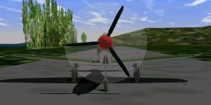
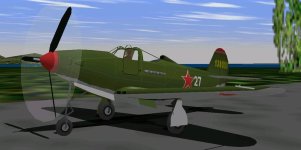
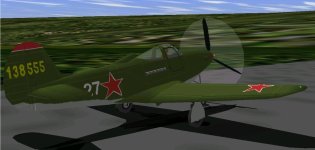
Here are some screenshots.
I haven´t re-done the Nose Glue-sequence yet, and that is next in the line now.
I also have to fix the filled-in triangles in the main landing-gear braces. They always happen after the re-scaling for some reason.
I´ve also just seen how the pitot bleeds through the wing in the rear-view.

Cheers,
Aleatorylamp
 

Attachments

  • -front.jpg
    -front.jpg
    42.7 KB · Views: 0
  • -frontside.jpg
    -frontside.jpg
    42.6 KB · Views: 0
  • -rearside.jpg
    -rearside.jpg
    43.5 KB · Views: 0
Last edited:
Hello Aleatorylamp,

Maybe a Museum example would be a good thing. Maybe not.
I don't happen to own a tape measure that is anywhere near as precise as the numbers I am getting from these drawings.
Precision would be about the same as scaling from a 1:48 scale Plastic Kit.

Regarding the Big Favour:
Instead of scaling one measurement for you, I sent you the Monografie drawing I am working from. Check your email.
You can determine whether it is useful or not.
I may have a large resolution photograph of a P-39, so I will check.

Be careful about pulling numbers from the diagrams I posted.
Note that the Aeroproducts Propeller (AeroProp) on my P-39F is probably listed as 10 feet 4 inches in diameter.
The manual that was distributed by the manufacturer claims the actual diameter is 10 feet 4.5 inches.
I haven't found the Curtiss Electric manual yet.

Your model doesn't look bad at all.

Tonight I need to write some more spreadsheets to calculate control effects.

- Ivan.
 
Last edited:
Hello Ivan,
Excellent! That´s an even bigger favour! It will help me contrast the other diagrams I have.
Then, I think there are some orthogonal photos in some of the manuals I downloaded, so those will probably also be useful.
Many thanks, also for your good words on my model!

Update:
I´ve just measured the area I was asking about before, and it seems that my original calculations and subsequent re-scaling

to correct length and height, have been surprisingly close. I have 5.85 ft height for that area on my model, and the scale on
the very high resolution drawings you sent me indicate 1.777 metres there (I drew in 10 more lines into the smallest division
of the
metric scale on the drawing), and that gives 5.83 ft. Very pleasing indeed, I´d say.
OK, I´ll be on the lookout for more accurate propeller data. For want of further information, at the moment I have it
at 10.4 which actually gave me the best fitting performance curve compared to smaller or larger diametres.

More tomorrow.
Cheers,
Aleatorylamp
 
Hello Aleatorylamp,

You can see by the size of the email attachment why I did not just post it here.
I may post a low resolution version here though.
I don't know if the P-39F drawing will be as good as the one for the P-39Q I was working with earlier because I am not done with the edits yet.
My scaling from the drawing gives 5.89 feet which is a bit higher than what you are getting.

Did you notice that although the drawing is a P-39F, the Cannon Barrel looks more like a 20 mm?
By the way, the Monogram P-39 is also a 20 mm armed version. The weapons bay is detailed with a removable panel and the magazine for he cannon is a drum rather than the circular ring magazine for the 37 mm. The external cannon barrel is also long and thin.

I believe your handling of the Propeller is a bit strange. Normally it is a matter of using the proper dimensions and adjusting the ret of the parameters. You seem to be doing it in reverse.
I almost have my AIR file set back to where it is supposed to be.
Maybe it can be tested again tomorrow.

- Ivan.

- Ivan.
 
Hello Ivan,
I just spent an hour answering your post, but it timed out and I forgot to do a backup and lost the whole thing.
Here´s a summary:

The wing/fuselage proportion between the new P39F drawings and the P39Q is the same, and putting in 10 extra lines into the metric scale and carefully pasting it, gave 9.08 metres, i.e. 29.79 ft, which is good enough for me. I´m not going to go crazy over differences of 1.44 inches.

The 20 mm Hispano cannon could perhaps be the one with the saddle-shaped drum containing 60 rounds? The Russians also fitted their 20 mm SchVAK cannon to the Airacobra, returning a number of cannon to the Americans. The SchVAK had 96 oz rounds.

The reason I fitted the 1.4 ft propeller before doing anything else after it was clear that the 11.5 ft one was only for later models, was because it was the simplest maneuever, and gave the best results so far. I also tried the BV.141 propeller as well as simply dropping the P51d propeller-graph slopes to zero, but this gave slightly less performance and would have required further adjustments elsewhere, which I wasn´t up to at the time, but which I may do later on.

Anyway, I´d say it´s going very well with the dimensions and shapes.
So... I hope this message doesn´t get lost.

Cheers,
Aleatorylamp
 
Last edited:
Hello Aleatorylamp,

I believe you will get better precision if you scale the drawing differently.
Determine one measurement as absolutely correct and see how everything else calculates out.
Depending on the drawing, I have picked different measurements, but the result has been amazingly consistent.
I have not been using the little scale marker in the drawing because even one pixel difference causes pretty substantial errors overall and it is hard to draw something more precisely than one pixel!

On the original P-39Q drawing, I wasn't sure about the overall length of the Fuselage, so I scaled the drawing based on the Wing Span at 34.00 feet. On the latest P-39F drawing that I sent to you, I scaled based on the Distance between Spinner Tip to Rudder being 29.91 feet.
I have not yet tried looking at the Plan View of the P-39F yet, so I can't tell you if things will measure out as consistently as everything else has.

I picked this set of drawings because it has an extended Landing Gear, but now that I check the dimension, I am pretty sure that the Landing Gear is pretty much Garbage and I will have to adjust the drawing by moving things around so that they all line up.

Note that if you rotate any of these drawings so that the Thrust Line is level, the Main Gear Struts are at an angle and from photographic evidence, this appears not to be the case on the real aeroplane.
Note also that the EJ model has the Main Gear Struts perpendicular to the Thrust Line and when the Thrust Line is inclined as when in a static position on all three wheels, the Main Gear Struts are also inclined but in the opposite direction.

Last night, I did a very cheap calculation instead of a full spreadsheet with graphs and it appears to be good enough for now.
Eventually I will want the better tool though.
I also tried swapping in the Propeller from the Kawasaki Ki 61 and performance got REALLY bad.
Speed at 500 feet went from 314 MPH to 288 MPH.
I will need to do a few calculations to see what the differences are.
These Propeller Tables were obviously not intended for this aeroplane but I am certain things can be adjusted.
All I was really looking for was the Table Structure which seems to be a good math cfor this model of Airacobra but probably won't fit another model because of different propeller pitch limits.

- Ivan.
 
Last edited:
Hello Ivan,
Normally I always draw scales to known values, but there was some hassle in the house under the stairs where I have my corner yesterday and today, and I couldn´t get the time I wanted, so for the time being I thought I´d be really smart and take a short cut for some quick checks.

However, I agree with you that cutting and pasting the on-plan metric scale to measure things has its shortcomings!

Not to worry! I´m scaling it now to put it into serious use to double check some areas.

I have also rotated a copy of the P39F side-view plan to get it into flight attitude, and I noticed the walk-ways on the wings that I haven´t
put on yet. I´ll check the landing-gear angle. Thanks!

Regarding the propeller tables, to use the graphs that drop down to zero, I remember now that I was a bit thwarted because I didn´t know
where to start the adustments. That was the reason I didn´t feel up to it, so I had to give it a miss.

Must rush now.
Cheers,
Aleatorylamp
 
Scales and measurements...

Hello Ivan,
I scaled the P39F drawing and with 34 ft wingspan I got a length of 29.85 ft instead of the previous 29.91 or 29.92.

At the end, I believe trying for this kind of precision depending on which drawings one is going to use, can be a bit of a nightmare.

Quite apart from the more "normal" discrepancies I (we) have already found, for example:
A) A document called P39D Flying Qualities.pdf, that has a diagram showing 30 ft 2 inches measured from the spinner tip to the tail.
This one also gives a measurement from spinner tip leading edge, which is of course a bit different too!
B) Another technical document called P39_draft.pdf, giving 30 ft 2 inches measured from the tip of the cannon!

Anyway, using the newly scaled P39F diagram, the height at "my" cabin/fuselage vertical distance reference point is 5.87 ft, and
measured with the on-plan metric scale, this gives 1.79 metres, the correct equivalent. So in this case, one could say that the
metric scale is quite accurate.

As I mentioned before, my model measures 5.85 ft at this reference point, so it´s still fine. My previous measurement here was
unfortunately incorrect because I measured to a part belonging to the bomb-clamp, not the belly undersurface.

So fortunately, I have been able to confirm that no fuselage/canopy height changes will be needed on my model!
Cheers,
Aleatorylamp
 
Last edited:
Hello Aleatorylamp,

Thanks for the warning.
The drawing I had scaled for proportions was actually a P-39F on another page.
Although the Plan scales out, the Profile does not. It works out to 29.97 or something around there if the Plan is correct.
The reason I had not use that drawing is that it did not have extended Landing Gear and also because the Plan view was of the underside.
Most of the interesting stuff is on the top side.
I had made the assumption that all their drawings were the same precision.
In any case, I probably have spent enough time chasing drawings, so I will probably go with the marked up version that I sent to you and make corrections as needed when I know the proper stated dimensions. I will also do comparisons against the P-39Q which may be better.

I will also do a non-proportional stretch on the plan view before I use it.

My next task will probably be working on the Propeller Tables which should probably cover in the Airacobra thread because the information doesn't really match your P-39D-2 anyway.

I actually thought I had posted this several hours ago, but it does not show.

- Ivan.
 
Hello Ivan,
OK then, it seems that slowly enough reliable material has been collected so as to be useful for your purposes,
...and mine!.


I recently came across an interesting .pdf document: The Pilot´s Flight Operating Instructions for Army Models
P-39K-1 and P-39L-1. Although of course it doesn´t refer exactly to the P39D-2, it does contain the
Specific Engine Flight Chart for the V-1710-63 engine!

I suppose this would be more exact as to the operation of the V-1710-63 engine on the P39D-2, than the
Allison Factory Engine Specification Document, that includes all kinds of other engine capabilities which were not
put into practice on the P39D-2. Probably it would be a good idea to limit WEP to the maximum of 51 Hg MP instead
of 57 or 60 the engine was capable of.

The document also contains the Take-off, Climb and Landing Chart, Flight Operation Instruction Charts and Weight and
Balance Charts for the P39K and L versions, which may be a good guideline. Let me know if it would be interesting to
post snapshots of those pages.

Cheers,
Aleatorylamp
 
Last edited:
Hello Aleatorylamp,

I actually have that manual as well and have had a copy of the SEFC sitting by my Development Computer along with the SEFC for the P-39D.
The reason I have not suggested using it is because it does not account for the War Emergency Rating that other sources describe.

No need to post snapshots of the other page since I also have the manual.
Note that the weights may not be quite the same as for the D-2 that you are building so be careful.

Last night I did quite a bit of editing for the Record 512 - Power Coefficient Spreadsheet to correct it to my best guess of where it should be for the P-39F. Today I made a slight modification to the Zero Lift Drag and also made a slight tweak on the Record 511 - Propeller Efficiency Spreadsheet.

Results thus far are
311 MPH @ 500 feet
369 MPH @ 12,500 feet

I would have wanted the speed to be about 3 MPH higher at 500 feet but am not dissatisfied with the results thus far.
I may revisit the Power Coefficient Spreadsheet to see if I can improve things a bit.

- Ivan.
 
Hello Ivan,
Now it´s my turn to say thanks for the warning!

I won´t change WEP in that case, and OK too about the weights - I was aware about that.

The performance achieved with your new propeller tables looks very good!
Cheers,
Aleatorylamp
 
Hello Aleatorylamp,

I wasn't quite satisfied as you can tell, so I did some more tuning.
First, I edited Table 512. The edits were quite serious but really only resulted in about 1-1.5 degrees change in propeller pitch.
With that, the speed at 500 feet came up to 314 MPH which is where I wanted it, but speed at 12,500 feet was somewhere over 371 MPH.
I made a few manual edits to Table 511 (only about a 1% change in two entries and speed was back down to a more appropriate 369 MPH.
I actually made changes to two other entries but that was to smooth out the curves and also are beyond the maximum level speed, so really were not necessary.

There may be a few more tweaks and adjustments, but from a level speed standpoint, I believe I am done.
Next step is to test and adjust the Service Ceiling and Climb Rates.

- Ivan.
 
Hello Ivan,
Very interesting indeed!
I´ll have to have another go at the propeller tables, if only because of the shape of the default P51d Table 511 graphs.
There are so many of them compared to the 2-pitch-position propeller, that I´m still skiving...

Then, on your P39F drawings, I measured the distance from the spinner-tip to the leading edge, and I´m about 2 inches short.
This will allow room for an improvement on the now vertical leading-edge parts. As a result, the 4 air-intakes can be placed more
correctly, and the textures for that area will correct themselves as well.

I´ve already moved the landing-gear parts into the Nose Group, with a little rear section of wheel-well and doors in Gear Centre,
and it seems to work quite nicely! As per your glue-sequence list for that area, I separated the long brace from the strut because
it was bleeding through the doors, and fitted it into the glue-sequence, and it also worked as soon as I´d figured out how to put
in the corresponding glue template.

Now I´m getting a strange vertical light grey "V" shaped trianglular artifact between the two parts of the wheel-well.
Update: It seems to be the Nose-part of the black insignia Wheel-well that is not covering all of the lower nose panels,
so I´ll revise the glue-sequence. It wasn´t working very well with a complete nose component because of the number
of parts involved, and I had tried a separate lower-nose component again, but it isn´t working here either. I´ll see...

Cheers,
Aleatorylamp
 
Last edited:
Hello Aleatorylamp,

The Split Nose Wheel Well also leaves a little gray part of the underside of the Nose visible from the front.
I believe this is unavoidable unless other measures are taken to eliminate it.
The problem is that the "other measures" are likely to cause problems as well and to me, this is a small consequence because from most angles it appears fine.
It comes from a Flat Nose Wheel Well being Glued to a peaked underside. Now you can make the Nose Wheel Well into a Component, but to me that is a waste and it certainly won't do as a single mostly planar Part. You could also split it into a Left and Right Nose Wheel Well, but that seems to me to be more complication than it is worth on this model.

Regarding Propeller Tables:
This is a pretty big can of worms. Be prepared for things looking pretty crazy when and if you decide to swap out the tables.
I have a pretty good idea of what I am doing and have a made a lot of tools and programs to work on this specific problem and it still took me about 5 tries to get things the way I wanted even though I could easily tell where the problems were.

- Ivan.
 
Hello Ivan,
Thanks for the advice and opinion on the Nosegear department! It pretty well seems that upto now, several
different maneuevers including my previous one with the elements in Body Main, all leave one or two flaws,
and as you say, there could be additonal solutions but they would be complicated, with debatable results.

Nevertheless, your observant comment on the origin of the problem being the flat wheel-well glued to the
peaked undersurface, has given me an idea:

I´ll try and flatten out the lower nose area, adding horizontal panels so that the area is flush with the wheel-well.
This would start with a triangle at the lowest point on the spinner disc / front nose, and continue aft as rectangles,
hopefully merging with the flat undersurface at the wingroots... I´ll see how it goes!
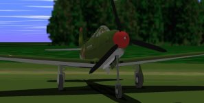
Update: It worked! I still have to clean up some cracks and some joints, and fix the textures a bit better, but it did
go very well! Here are some pics. Now for the inboard air intakes and the leading edge!

Regarding the implementation of a Propeller Efficiency Table 511 with a more correct graph shape, i.e. dropping down
to zero after the crest (like on your BV-141): The short tests I have done upto now, gave an all-round loss in performance,
so perhaps a first try to remedy this could be to slightly raise the point on the graph just prior to the drop.
Perhaps I can avoid having to alter the graphs in table 512... and only ONE worm will come out!! Let´s see how that goes!

More later,
Cheers,
Aleatorylamp
 

Attachments

  • Front1.jpg
    Front1.jpg
    37.2 KB · Views: 0
  • Front2.jpg
    Front2.jpg
    33 KB · Views: 0
Last edited:
Hello Aleatorylamp,

Regarding the Nose Wheel Well, I am just going to leave it as it is for now.
There are worse things that are still wrong in my opinion.

Regarding Propeller Tables:
My belief is that in general, all the Record 511 - Propeller Efficiency Tables will be very similar in appearance with just some small variation in peaks and slight adjustment in slopes. The real difference will be in Record 512 - Propeller Power Coefficient which needs to match the Engine and Propeller characteristics with the Efficiency Graph. I won't say it is easy or really that difficult, but it IS tedious and don't expect to get it on the first try.

My next task is actually to edit the Propeller Efficiency Table to bring the Climb Rate down a bit.

- Ivan.
 
Hello Ivan,
OK, I´m warned about the graphs! Let´s see if I can manage something along the performance lines I´m looking for.
Perhaps the reason it´s working more or less OK at the moment is because of the strange rather incorrect slopes on the graphs...

Well, as I got other shapes a bit better, I suppose that improving the nose-gear was good in my case, and the leading edge shape
improvement is progressing quite well too. Now there´s even less of the original model in it!!
Probably only about 7 and a half vertices... per side, at most!

With all the panels added all over the place, the numbering is quite obnoxious - I just added letters to the panel names of
adjacent panels, and it is not totally logical. Anyone trying out the AFX would most probably have a fit.

Cheers,
Aleatorylamp
 
Hello Aleatorylamp,

Just be warned also that for me to figure out a workable pattern for the Power Coefficient Graph took more time for the first successful result than we have spent thus far on the P-39 visual and flight model together and the process is still being refined. Perhaps I might have gotten there more quickly if I had a better background in the subject.

In my opinion, you are correct. The reason the P-51D Power Coefficient Graph works is BECAUSE it is pretty messed up.

Let's see:
7 1/2 Vertices unaltered per side.
You still have a crazy Parts naming scheme.
The Wing Cross sections are probably still messed up.
The original mislocated pieces are probably still mislocated because I suspect you did not attempt to move pieces to their proper locations.

These factors coupled with the fact that it still is someone else's AFX from a copyright standpoint is why I decided not to take that path.
Then again, you are about done and I haven't even started mine yet.

- Ivan.
 
Back
Top