Analysing and modifying the AFX file with QBasic.

Hello Ivan,
The Curtiss Electric Propeller used on some of the Airacobras seems to be the most elusive of all pieces of information.

Some of the different performance tests mentioned on http://www.wwiiaircraftperformance.org/P-39/P-39.html, make
reference to propeller pitch, or blade angle range, and blade design number, but if they are going to be useful to you is
another matter.

I´m looking now, and this information is mentioned for the -C, the -D, -M, -N, and -Q variants, but unfortunately there
there are no -F or -K versions mentioned, I´m afraid.

However, the -M version is mentioned as having a V-1710-83 engine and "a three-bladed Curtiss Electric constant speed
propeller, blade design No. 614-1C-1-5-21, blade angle range 26º to 56º, at 42 inch radius
."

This is the only piece of information detailing numbers for a Curtiss Electric Propeller that I´ve come across. I believe the
-M version was a derivative of a more commonly named other version, but off-hand I can´t remember which.

One relationship between Tables 512 and 511 that I do realize, is something you mentioned some time ago, and is clearly
visible on your BV-141B propeller tables, namely that for any given pitch angle, the curves on both tables drop to zero
at the same "J" Factor.

Now: Were I to
1.- give, in Table 512, the 35º pitch-angle Graph (and perhaps move it to be 34º), at "J" Factor 1.77
(or 1.8, to round off), a Power Coefficient of 0.1422, then
2.- even out the rest of the graph curve shape for J=1.8, and after that
3.- put all the rest of the graphs to zero at the points coinciding with the propeller efficiency table, and finally
4.- "sculpture" the rest of the graphs to fit the surrounding shapes.

...perhaps that would not be so meaningless, and would have a good effect. Then next step would be to do
something similar for the 40º pitch graph and finally for the 25-30º one, but not at the "J" Factor positions you
mention for your P39F, but for the "J" Factor corresponding to the calculation of the P39D-2 propeller 1.4 ft
approximation with 2:1 gear ratio I´m working with.


I wonder...
Cheers,
Aleatorylamp
 
Maybe more meaningful.

Hello Ivan,
I just did this and tested for S.L. performance, without yet adjusting Torque or anything else, just Table 512 to match the Zeros on Table 511, and smoothen the graphs after putting in Power Coefficient 0.1422 at Advance Ratio 1.8 for the 35º pitch graph.

The perhaps significant result was that at 314 mph, the simulator selected 34.8 pitch, albeit with 78% WEP to obtain the 1220 Hp it needed.
With as yet unadjusted Torque/Drag, Normal 44.2 Hg Military Power gives 1082 Hp (as before), but only does 285.6 mph, with 29.8º pitch.

Perhaps this is now becoming meaningful. Probably now would be the moment to adjust Drag and Torque to get some more power into Military power setting. As 1220 Hp would expectedly be a bit high, by reducing Drag and increasing Torque the aim would be to get 314 mph with about 1150 Hp, graduating it so that 1550 Hp would be available with WEP at S.L.

This probably sounds a bit more coherent with the objective.

Cheers,

Aleatorylamp

P.S. By the way, I recently read that later Airacobra models had a power limitation for take-off, around 1100 Hp.
I would suppose this would have been for due to the better altitude performance achieved with greater supercharger
capacity, perhaps on later -Q versions, so at S.L. the supercharger would not be used, in order to protect the engine.
 
Last edited:
Further adjusting

Hello Ivan,
Instead of the two updates on my last post, I decided a separate post would be better, so the Updates are contained in this one:

I had noticed that it was better to adjust only Propeller Efficiency, also making fine adjustments in the Power Coefficient table, instead of changing Torque and Drag.

Changing Torque upset the 1550 Hp WEP setting, so I discarded that.
Then, only adjusting Drag corrected S.L. performance to 314.0 mph with 44.2 Hg Military Power 1083 Hp, and 34.3 degrees propeller pitch.
However, engaging WEP caused speed to shoot up beyond 370 mph, so the Drag adjustment didn´t seem much good either.

However, with normal military power now, 44.2 Hg, speed is only 290 mph.
Maintaining 314 mph at S.L., requires 45.2 Hg and 1120 Hp, and propeller efficiency is already very high. Nevertheless, Propeller pitch is 34.4.

Later I also regulated performance at 13000 ft by adjusting the 40 deg. pitch graphs around J=2.
The result with 44.2 Hg Military Power, is 372.7 mph with 40.0 degrees propeller pitch. This would seem quite good, I believe.

Now it is a matter of seeing how S.L. performance can be ironed out.
Perhaps the Power Required Coefficient at J=1.8, where you suggested an entry of 0.1422, was only an approximately calculated value to start off with, and could now be decreased a little?


Cheers,

Aleatorylamp
 
Hello Aleatorylamp,

Aleatorylamp said:
The Curtiss Electric Propeller used on some of the Airacobras seems to be the most elusive of all pieces of information.


I am asking because the AIR file for your P-39D-2 needs this data and I am curious as to what you are using.
You seem to be somewhat vague on the Propeller Diameter and have not mentioned Pitch Ranges, both of which are important for what you are doing.

*I* don't need the data because the P-39F and P-39K both use propellers by Aeroproducts and not Curtiss Electric and I have all the specifications I need for the models I need. The P-39D and P-39D-1 information is also not hard to find even though I don't need it for what I am building.
Incidentally, the Aeroproducts "Aeroprop" was actually a Hydraulically controlled propeller in a similar manner to the Hamilton Standard Hydromatic but obviously without the piston in the center where the Cannon would go. I haven't actually spent the time to look for the data myself because I am not building that model of Airacobra and the propeller for the P-39D-2 was probably quite unique which is why you need it.

Aleatorylamp said:
One relationship between Tables 512 and 511 that I do realize, is something you mentioned some time ago, and is clearly
visible on your BV-141B propeller tables, namely that for any given pitch angle, the curves on both tables drop to zero
at the same "J" Factor.


This is what prevents the feedback / Perpetual Motion business. In reality, the Efficiency would drop to zero slightly ahead of the Power Coefficient because of Frictional losses in the system.

Aleatorylamp said:
I just did this and tested for S.L. performance, without yet adjusting Torque or anything else, just Table 512 to match the Zeros on Table 511, and smoothen the graphs after putting in Power Coefficient 0.1422 at Advance Ratio 1.8 for the 35º pitch graph.

The perhaps significant result was that at 314 mph, the simulator selected 34.8 pitch, albeit with 78% WEP to obtain the 1220 Hp it needed.
With as yet unadjusted Torque/Drag, Normal 44.2 Hg Military Power gives 1082 Hp (as before), but only does 285.6 mph, with 29.8º pitch.


Hmmm.....

Aleatorylamp said:
Some time ago, I did write two QBasic programs along the lines you suggested in your post, but for the moment,
the whole issue is a bit cumbersome to handle, I´m afraid.


It seems to me that you should actually use those QBasic programs you wrote.
You do realise that 1220 HP instead of 1082 HP will significantly change the Propeller Power Coefficient, right?
By my calculations, this puts the new Power Coefficient at 0.162.
I can't actually help you much without actually doing all the calculations you will need and I don't have the data for that.

My advice to you if you really want to pursue this is to:
1. Build a listing of Power versus Altitude for the Engine you want to use.
2. Use your program to calculate the Propeller Power Coefficient at Each Altitude.
3. Graph Table 512 BUT along with Advance Ratios, list the corresponding Level Speeds.
4. Do a quick test of Power Coefficient at War Emergency Power just to get an idea of the extreme values but tune for Military Power only.

This is the basic background work I believe you will need to get a feel of what is going on.
I did this before ever starting work on the P-39F Propeller Tables because without it, I can't visualize the relationships.
I do this with Spreadsheets, but you can do this with any tool you want though I suggest you have at least a good pocket calculator.

My Children have the Texas Instruments Ti-89 and Ti-84, and I have a Ti-83 Plus which are all Graphing Calculators but I don't actually know how to use any of them..... (Mine actually cost me about $5 at a Thrift Store.)
One of these days I will ask them to teach me.

- Ivan.
 
Hello Ivan,
There are several as yet unknown factors which require speculation, and consequently cause problems.
I don´t know what the characteristics of the Curtiss Electric Propeller were.
It appears that the D-2 had one of these, but many sources don´t even bother to say.
The -L version was a -K version (with a -63 engine) with some modifications, which included a Curtiss Electric Propeller.
The -M version had a Curtiss Electric Propeller too, but with a -83 engine, and then for the -M1 version, the propeller
was changed to an Aeroproducts one.


So, being the 1200 Hp -83 engine, with a "a three-bladed Curtiss Electric constant speed propeller, blade
design No. 614-1C-1-5-21, blade angle range 26º to 56º, at 42 inch radius
.", I wouldn´t know what to guess for
the propeller on the 1325 Hp -63 engine.

Using my general-approximation 1.4 ft propeller, I could of course incorporate the 26 to 56 degree angle range,
but I doubt that it would make much difference for the reading of 35 (or 34) and 40 degrees.

At the moment, the progress I have made so far seems to indicate that I am getting somewhere after all, and
I have identified the J-factor positions needed to regulate the Power Coefficients.

The 1220 Hp needed to get to 314 mph at S.L. were only at the beginning when I was regulating Table 512 at
the 35-degree pitch graph, with position J=1.8, without having regulated anything else,
for example Propeller Efficiency
(because Torque and Drag adjustments seriously messed other things up).
Also, 1220 Hp for
Military Power is totally erroneous anyway, as Military Power is 1150 Hp as per specs.
After raising Propeller Efficiency, it only required 1120 Hp to reach 314 mph.

There is a possibility that 314 mph is too fast anyway for the D-2. Some sources state "306 mph near the ground."


The problem with putting in 1150 Hp, or even 1120 Hp for Military Power, is that WEP goes out of control, and to
keep WEP at 1551 Hp,
Military Power has to stay at 1083 Hp.

Now, a really strange problem:
Trying to get to 314 mph with Military power is impossible, because it won´t go beyond 290 mph if it is accellerating
from a slower speed,
but if one reaches 314 mph with WEP and disengages WEP, then Military Power strangely accellerates
further, to 320 mph or more.


At 13000 ft, however, it is perfect: 372.2 mph with 1232 Hp at 44.2 Hg Military Power, with 40.0 degrees propeller pitch.

Anyway, it seems that there are still too many unknow factors to be able to do anything concrete other than speculation
and/or trial-and-error experimentation to try and regulate performance at 500 ft.

Cheers,
Aleatorylamp
 
Hello Aleatorylamp,

Aleatorylamp said:
Using my general-approximation 1.4 ft propeller,

You do realise of course that a 1.4 feet Propeller would be so small it would actually fit entirely inside the Spinner, right?
I was thinking that this was a mistake when I first saw it, but it has shown up a couple times, so you must really mean it.

Aleatorylamp said:
The 1220 Hp needed to get to 314 mph at S.L. were only at the beginning when I was regulating Table 512 at
the 35-degree pitch graph, with position J=1.8, without having regulated anything else,
for example Propeller Efficiency
(because Torque and Drag adjustments seriously messed other things up).
Also, 1220 Hp for
Military Power is totally erroneous anyway, as Military Power is 1150 Hp as per specs.
After raising Propeller Efficiency, it only required 1120 Hp to reach 314 mph.


Your reasoning really has me confused here.
The 1220 HP would raise the Power Coefficient well above the value you were trying to tune Table 512 for, so I don't see how that could help at all. If you change too many parameters, it is hard to tell what the interactions are (in my opinion), but if you are getting satisfactory results, then you must be following a process I do not understand.
If it works for you, keep using it. I believe I will stick with the process I understand.

Aleatorylamp said:
Now, a really strange problem:
Trying to get to 314 mph with Military power is impossible, because it won´t go beyond 290 mph if it is accellerating
from a slower speed,
but if one reaches 314 mph with WEP and disengages WEP, then Military Power strangely accellerates
further, to 320 mph or more.


I believe you are running into an interpolation problem as I described back on the "Flying Swallow" Thread last year.
http://www.sim-outhouse.com/sohforu...ying-Swallow?p=1082255&viewfull=1#post1082255

- Ivan.
 
Hello Ivan,
I forgot a zero...
highly_amused.png
It´s a 10.4 ft propeller!

Perhaps I didn´t explain what happened with the 1220 Hp very well. I had done the corrections on Table 512 to get the same columns crossing the zero line as in Table 511, smoothening them out as well. Then I had adjusted the graph for J=1.8 to a coefficient of 0.1422, giving that graph a smooth shape as well, and I didn´t do anything else for the first test.

Just with 44.2 Hg 1083 Hp Military power I only got about 285 mph. To get to 314 mph, I had to apply WEP, and adjusting the throttle, it needed 1220 Hp to reach 314 mph. The propeller sets itself to 34.4 degree pitch at 314 mph, so that must be correct.

Then I increased propeller efficiency at J=1.8 for the second test, and it now only required 1120 Hp to get to 314 mph.
With only Military Power I´m getting 290 mph. Of course I tried regulating Torque and Drag, but that seriously messed things up elsewhere.


Thanks for the indication on the interpolation problem. I had a look at last year´s "Flying Swallow" Thread, and it seems to be a case of the sim not selecting the pitch it should, probably because it interpolates insufficient power to get there.

Update: I fiddled around with the graphs, both the 30 degree and the 35 degree ones, to give a little more power and speed in the 290-310 mph range. This made the sim select a better pitch, which now at 314 mph is a little higher than before, 34.6. Speed goes a little over 314 mph, to 316, but it is unavoidable as otherwise it will fall short again.

Not very easy, this one, but it worked.

Thanks again for pointing me in the right direction!
Cheers,

Aleatorylamp
 
Last edited:
Hello Aleatorylamp,

For the Kawasaki Ki 61 Flying Swallow, the Propeller Pitch Selection seemed to be working as it should.
The problem as I stated was that it was an interpolation issue.
In other words, there are only Specific entries for 30 Degrees and 35 Degrees.
If the actual pitch happens to be 32.5 Degrees, there is no direct Graph, so the computer averages the values that it has for the 30 and 35 Degree curves. Look at the Dotted Line that is plotted there and you will see what happens.

For your Military Power test, you are focusing your concern at J=1.8 (319 MPH) but the problem that you are encountering is not there.
You got stuck at J=1.6 (284 MPH).
This is why I suggested that you label your Graphs with actual MPH as well as the Advance Ratio.
Please observe that I did that with the Graphs for the Ki 61.
I don't see those numbers very well without a converter either.

The other thing worth discussing is: Why are you using 0.1422 for a Propeller Power Coefficient?
Is it because that is what I stated a few posts back? Are you sure my number is correct?
What do your own programs tell you the Power Coefficient should be?

I can tell you that I have two or three spreadsheets that all do some calculations with Propeller Power Coefficient.
They don't all agree with each other. The error is around 1% which I believe is due to differences in conversions and precision for Air Density but there might simply be an error in one or more of the spreadsheets.

By the way, messing with Engine Torque and Aerodynamic Drag is a really bad idea when you are trying to tune the Propeller Tables.
You are trying to tune specific areas of the Tables to have a very local (in speed) effect and the Engine Torque and Drag have a general systemic effect at ALL speeds.
Use it later for fine tuning if you absolutely need to but by that time, things should be pretty much under control and you are only trying to tune a couple MPH over the entire speed range.

- Ivan.
 
Hello Ivan,
Well, it worked out quite well, and I quite soon found out that Torque and Drag were best left alone!
It´s not perfect yet, but I´m tired so I´ll continue tomorrow, although 316 mph at S.L. is just about acceptable for military power.

You are right, with the 35 degree graph, I had to work on the J=1.6 column, but also bring down the J=1.8 column from your 0.1422 to 0.135
because 0.1422 was really meant for J=1.77, and mainly because it was (and still is slightly) overshooting the 314 mph mark.

Then, I not only had to regulate the 35 degree graphs, but also the 30 degree ones, because the pitch I was getting at 285 mph or 290 mph, was 31.1 and 31.6 degress. Of course, that required ironing out the graphs at J=1.4 as well. Giving a bit more power and speed with the graphs got me over the kind of "wall" there seemed to be between 290 and 312 mph.

Anyway, I found it very interesting indeed - not only fixing the interpolation problem, but the whole activity of working on this kind of propeller.
The pennies started dropping when I saw the graph tables of your BV141B, and remembered that the graphs in table 512 had to go to zero as well as those in table 511. After that, I could visualize a kind of pattern, and things started falling into place.

So, thanks very much again! Cool stuff!
cool.png

Cheers,
Aleatorylamp
 
Propeller Division of Ivan's Workshop

Hello Aleatorylamp,

Have you thought for a moment that I, as Chief Engineer of Ivan's Workshop, give an impression that I know what I am doing but if you look at what has actually been accomplished, perhaps it is a bit overstated.

The Propeller Division of Ivan's Workshop is very new.
We have only designed 4 Propellers and perhaps provided Technical Support for another 2 Propeller projects.
Of those Propeller Designs, only TWO are in Production. (FW 200, and BV 141B)
The Kawasaki Ki 61 remains stuck for various reasons.
The Airacobra is still in the Development stage.

There is a lot of Research happening, but not a lot actually leaving the Workshop.
The main objective when creating the Propeller Division was to be able to produce Aircraft that could not be built properly with Propellers that are available, but that objective seems pretty far off at the moment.

- Ivan.
Lead Engineer,
Propeller Division.
 
Hello Ivan,
Aren´t there three propellers that came out of your department? There was a wooden fixed-pitch propeller,
I believe based on your Eindecker one, which I was whittling away at and sanding off with technical support
from your workshop.

Then, in my propeller department, there were two adaptations of the 2-pitch-position FW200 propeller, one
for the Stearman and one for the Electra.

This one is my first try at a CV propeller, with technical support from your department of course.
I´m sure that without your comments along the line, I would not have managed by any means. I admit I did not
understand everything you said, and I have arrived at some results following a slightly different path, but
everything does tie in with all you were saying.

Although level flight performance is perfect at Critical Altitude and acceptable at 500 ft, the propeller is not
by any means finished yet. The sustained climb test is still outstanding. I think I´ll do it with 50% fuel and full
ammo ( as it is lighter without the wing guns).

The other thing is trying to get the 316 mph down to 314. Here, there is a side-effect, (understandably):
The more I manage to lower this, the slower the speed progresses from 290 to 314 mph, upto a "danger point"
where it stops accellerating before getting there.

Interesting too, I thought, and resulting from overcoming the interpolation "wall" between 290 and 314 mph,
was that this
required performance improvements also on the 30 deg. pitch graphs, but thinking about it,
it seems logical I suppose.


Another strange thing is the rather low 1083 Hp setting at S.L. that the sim seems to stubbornly be demanding
for its 44.2 Hg Military Power. I´d be much happier with at least 1100 hp (the take-off limitation I read on one
source, seemingly for later models, although that wasn´t clear), and preferably 1150, which is in the specs.


It also comes along with a side-effect: Full 1551 Hp WEP can´t be set with 60 Hg, because power goes wild,
and WEP
must be kept to 57.35 Hg. For the moment, adjustments on these two items don´t seem possible.

Nevertheless, the differences lie within acceptable limits, and performance is behaving itself rather well, I´d say.

Incidentally, another improvement along the way: WEP at S.L., or rather 500 ft, is now giving a more logical
speed: 134.5 mph, not the excessive 158 mph I was getting before!

OK then, now for the sustained climb test!

Update:
And here is the sustained climb test, without any additional adjustments as yet:
I had to slew down to 1000 ft and let it travel to beyond 2500 ft several times, but finally, after the porpoising
settled down (under Learjet Autopilot), at 2500 ft, it appears to be able to maintain 2700 fpm at 180 mph,
with 1103 Hp and 23 degree. Pitch. Pitch and Hp are a bit lower than you had indicated, but seem OK to me.

The question is whether this would be OK with your understanding too... I wonder!

Cheers,
Aleatorylamp
 
Last edited:
Curtiss Electric Propellers

Hello Ivan,
On the War Department Performance Test page, it is apparent that, as I mentioned before,
it mentions the P39-M model with the 1200 Hp -83 engine had a Curtiss Electric Propeller,
reference number 614-1C-1-5-21, with a pitch range of 26-56 deg. and unknown radius,
which for the moment I had placed at 10.4 ft, i.e. 10 ft 4.8 inches.

The same page also mentions the -D Model with a -35 engine, and the propeller, although not
mentioned as Curtiss Electric, has reference number 614-1C1.5-21, suspiciously similar to the
previous one, but for the point instead of the hyphen in the number sequence, and gives pitch
range as 21.5 to 51.5 degrees. Radius is also unknown.

There is another document I´ve mentioned, P39DFlyingQualities.pdf, which has a rather broken
typewriter type-face, making it quite difficult to read. It covers the P39D-1 model with its -35
engine, and mentions it as being equipped with a Curtiss Electric propeller, but gives no further
details on it, except for an airplane diagram showing propeller diameter at 10 ft 4.5 inches.

Perhaps it is possible from this information, to piece together the Curtiss Electric propeller for
the D-2 model with its 1325 Hp -63 engine, with radius being 10 ft 4.5 inches, i.e. 10.3750 ft,
and pitch range being 26-56 degrees.

For the moment, it´s the closest I have managed to get, so I entered this data into the .air file,
and was able to establish that at 500 ft, the slightly excessive speed further increased to 320 mph.

Applying finer adjustments to the propeller graphs at J=1.6 and J=1.8 it has now been possible
to curtail the excessive level speed to 314.1 mph, and it will not go above that under military power.

The resulting fine-adjustment of the propeller radius has also increased sustained climb speed
to 191 mph, which would also be plausible compared to the figures you were giving for your -F model.

Slowly the picture seems to be getting more complete, which I find very satisfying!

One drawback with cutting 0.025 ft off the propeller is that at high speeds went, as the sim only selected
39 deg. pitch. So,
S.L. WEP was 1.5 mph slower than before, and at 13000 ft, top speed was 22 mph
slower!
However, tiny adjustments on the 40-degree propeller graphs at j=1.8 and J-2 fixed this very well.

Now I can continue with the textures on the fuselage.
Cheers,
Aleatorylamp
 
Last edited:
Hello Aleatorylamp,

Aleatorylamp said:
Aren´t there three propellers that came out of your department? There was a wooden fixed-pitch propeller,
I believe based on your Eindecker one, which I was whittling away at and sanding off with technical support
from your workshop.

The Eindecker Propeller really doesn't count. It is basically a modified Stock Propeller because I didn't know any better at the time.
There actually have been a lot more adaptations than mentioned thus far. The Bombers you were working on from the Great War had a few Propellers that had some influence from my shop.

Be careful about using specs for a Propeller from a different model Allison Engine. They tended to be significantly different in Diameter and Pitch Ranges and also in Reduction Gear Ratio.

I fixed another minor bleed in the Tail section of the EJ P-39D last night. It was an easy fix.

- Ivan.
 
Hello Ivan,
Well, as I commented before, without specific data one can only speculate, so there´s room only for educated (or uneducated...) guesses.

Unless you were to have a better suggestion for the Curtiss Electric Propeller, I would be inclined to use the 10.375 ft diameter propeller
I have now, with its correspondingly
fine-tuned Propeller Tables 511 and 512 to meet the conditions for the three test situations established.
It also seems to work better in the problematic interpolation "wall" area around 300 mph for military power, so perhaps it is another reason
to go for this diameter and 26 deg. minimum pitch.


Summarizing possibilities:
A) 10.375 ft is 10 ft 4.5 inches. I´ve seen this in other sources as well, not specifically for the D-2 version, but rather the D-1, or unspecified.
The 26-56 deg. pitch range of the propeller for the -63 engine also seems more in line with the -83 engine I got the pitch data from,
than the 21.5-51.5 deg. D-1 Propeller of the -45 engine, although it seems that the diameter was the same.

B) 10.4 ft, which I was using for want of anything else. This is 10 ft 4.8 inches, nowhere to be seen, thus presumably less probable than A).
C) The Aeroproducts Propellers on later versions produced shortly after these, I think were larger, so this size can be discarded.
I believe that on -Q versions diameter could be over 11 ft.


What size is the Aeroproducts Propeller on your version?


Re: the model itself:
Wings and wing-fillets now have a number of extra panels to make the surfaces less flat and angular - a bit more rounded - and also to
triangulate further disappearing panels. Fuselage textures now also fit the area better. I think there´s still one more disappearing panel
in the nose area that needs triangulating, but should be easy.


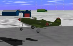
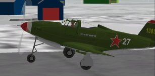
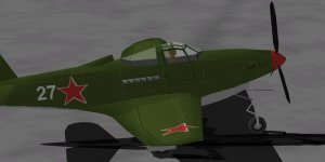
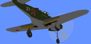
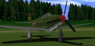
Here are some screenshots with a kind of Siberian ambience, although it is really the Danish Station Nord in Greenland.

Cheers,
Aleatorylamp
 

Attachments

  • Russia1.jpg
    Russia1.jpg
    46.3 KB · Views: 0
  • Russia3.jpg
    Russia3.jpg
    38.3 KB · Views: 0
  • Russia5.jpg
    Russia5.jpg
    26.1 KB · Views: 0
Flaps, and Curtiss Electric Propeller.

Hello Ivan,
I see you are making headway with the first phases of your new Airacobra Models.

A while back you were asking about how I´d solved the flaps-bleed problems, and I´d answered that wheel-wells were still bleeding through the extended flaps seen from behind.

Well, fortunately I´ve just managed to fix this by taking the wheel-wells out of Gear-Centre, eliminating the wheel-door glue there, and placing the wheelwells into Wing-Low left/right, together with a duplication of the animated flaps, and including a vertical glue template between them. Now it all works perfectly!

Only moving the flaps out of Gear left/right into Wing Low left/right is not enough, as they will allow the landing gear in Gear left/right to bleed through.

Another thing on the flaps: The inner flap section will perhaps have to be corrected, as long as it doesn´t interfere with the wing-root.
It seems not to be square, but should be more angular, nearing the fuselage centre on the flap trailing edge.

Re: Curtiss Electric Propeller, cont´d:
After finding the 10 ft 4 in. (10.375 ft) diameter of the Curtiss Electric Propeller used on early Airacobras, I noticed it was the same as indicated on several diagrams in documents on the airplane with Aeroprotucts Propeller. You had also had mentioned it in one of your posts a few days ago.

So both propellers were the same diameter, with differt mechanisms as can be seen on an exploded-view drawing showing both propellers simultaneously. The inner part near the hub can be seen as built differently.

I noticed that the same reference number is indicated for the blade design of the Curtiss Electric Propeller for different aircraft models, but the pitch range varies. Nevertheless, the movement is always a total of 30 degrees: 26-56, 21.5-51.5 or 21-51.

This would lead me to believe that the Curtiss Electric Propeller used on early models was always the same one, same diameter, same blades, but with a mechanism that allowed pitch-range to be set depending on the engine, so that the 30-degree movement could be made to start between 21 and at least 26 degrees.

The Aeroproducts Propeller on a -Q version had a range of 28-63 degrees, and I know -Q versions had larger diameters, and possibly -N versions as well.

In my last post I asked about the diameter of the Aeroproducts Propeller you were using, meaning the one on your planned P-39Q version, as you had already mentioned the diameter for your earlier P-39F version, but I forgot to mention the -Q version specifically!

Cheers,
Aleatorylamp


Last edited:
Flaps and radio

Hello Ivan,
The small correction in the shape of the inboard flap edge unfortunately (and expectedly) interacts with the wing-fillet,
so it´s not worth fixing and best left alone! I will, however, correct the inboard flap-line on the wing-texture underneath.

Update:
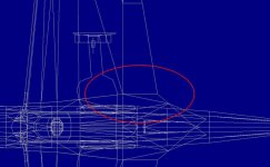
Unless of course, one were to modify the wing-fillet shape, bringing the outer edge of the component inwards,
along the red line on the screenshot, at that part parallel to the fuselage. Then the inboard flap edge would be flush with
it, and the inner part of the wing would
have to have a wedge shape added. ...All much too complicated, perhaps...
Update2: The best way is maybe an in-between correction: Make the flap-edge parallel without adding a wedge fillet to
the wing as per the screenshot with the red circle.
It isn´t a very obviously visible correction on the model, ...only a small
improvement,
but at least I know it´s better and it´s there!

Incidentally, I noticed that on earlier versions, the radio was placed inside a small compartment in the aft-fuselage.
Unfortunately, I haven´t been able to find out as of which later model it was moved to the aft-cabin.

Slowly the model is getting to a finished state, although I´m still checking for possible flaws, glitches and bugs.

I´ll also probably darken the grey landing-gear struts, to increase the contrast with the under-wing light-grey.

Cheers,
Aleatorylamp
 

Attachments

  • Top-view.jpg
    Top-view.jpg
    51.6 KB · Views: 0
  • Newflap.jpg
    Newflap.jpg
    63.2 KB · Views: 0
  • NewFlap2.jpg
    NewFlap2.jpg
    23.2 KB · Views: 0
Last edited:
Virtual Cockpit

Hello Folks,
Thanks to help from Ivan´s Workshop on different issues, everything seems to have come out pretty well,
better that I´d expected.

This applies to all aspects of the work involved in extensively upgrading and updating this model
from the original 1998 Eric Johnson AF5 AFX files:

- More accurate dimensions according the most recently found more accurate documentation.
- More correct positioning of the model´s centre of rotation.
- More rounded shapes all around.
- Corrected height of aft-fuselage and tail-empenage, belly-curve and nose-gear.
- More correct shapes for leading edge, wing, wing-root, and tailplane.
- More efficient glue-sequences to keep bleeds at an absolute minimum.
- Transparent Cockpit with pilot.
- Improved engine and propeller tuning in the .air file.
- SCASM-corrected Virtual Cockpit Chase-Mode View.

Then, the panel I´m going to use for the upload is a CFS panel by Dan Griffin, which was included with one of
the Airacobra uploads in 2005.
In my opinion it looks quite good and does the job.

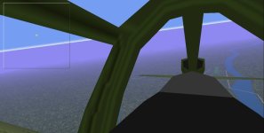
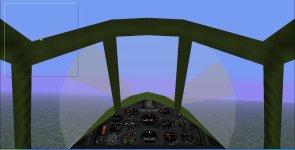
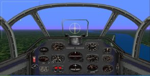
Here are some screenshots, also including two Virtual Cockpit views.

Now comes checking that everything is OK in the Dp files, writing the checklists and the readme texts,
and then the model will hopefully be ready for upload!

Cheers,
Aleatorylamp
 

Attachments

  • VCview1.jpg
    VCview1.jpg
    32.2 KB · Views: 1
  • VC-view2.jpg
    VC-view2.jpg
    37.8 KB · Views: 0
  • V-panel.jpg
    V-panel.jpg
    67.2 KB · Views: 0
  • Screenshot.jpg
    Screenshot.jpg
    42.4 KB · Views: 0
Last edited:
Not quite there yet!

Good morning!

As often happens, last minute adjustments were required.
Ivan´s latest post on his Airacobra thread mentions a more accurate fuselage width than the one I had,
which came in very handy indeed! Thank you once more, Ivan!

I had already corrected the original AFX´s fuselage width as per data obtained from the previous drawings
I was using, and it turns out that my fuselage was still just under 2 inches too narrow. This also led me to
check the tailplane span on the new drawings, and mine was still short by 3 inches per side!

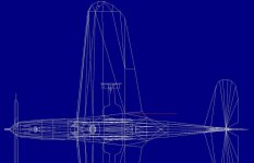
Thus, I made a copy of my AF99 build, took out everything except the nose, fuselage, cockpit, and tail empenage,
packed it into an AFX file, and ran it through my QBasic Modifier with a multiplier to get the fuselage width exact.

Then I unpacked the new parts into my regular build, adjusted the front nose panels to be flush the spinner,
manually fine-adjusted the tailplane span and re-compiled the build.

Admittedly, the corrections on the visual model are not noticeable, but I know they´re there, which is satisfying,
as one of my main aims with this model is to get shapes and dimensions as accurate as possible.


Now the only thing remaining is to re-SCASM the model for the virtual cockpit. This should be straight forward,
b
ecause expectedly, parts order will not have changed.

It turns out that the QBasic Modifier is certainly worth its weight in gold!

I was even dreaming of writing a QBasic Program to make custom-made Propeller Tables 511 and 512, so that this
will automatically and instantly create these tables accurately, instead of having to go through manual adjustments
on individual points on the different graph lines. ...No harm in wishful thinking, I suppose!

Cheers,
Aleatorylamp
 
Hello Aleatorylamp,

Aleatorylamp said:
As often happens, last minute adjustments were required.
Ivan´s latest post on his Airacobra thread mentions a more accurate fuselage width than the one I had,
which came in very handy indeed! Thank you once more, Ivan!

"You're Welcome" for the data. I was pretty sure you already had the data though because you posted a link to a PDF from the "Legends in Their Own Time" site in a much earlier post which I quoted in the Airacobra thread.

http://www.sim-outhouse.com/sohforu...-with-QBasic?p=1148142&viewfull=1#post1148142

For information content, this is the same as the "Design Analysis" article I am using but just in a less pretty and more readable format. The "Design Analysis" article is where I found the data I just posted and you clearly had that if you were posting a link to the PDF.

- Ivan.
 
Hello Rami,
In view of recent developments, it may be a good idea to delete this thread.
Thank you very much,
Aleatorylamp
 
Back
Top