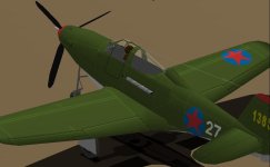
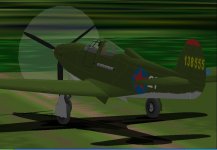
Analysing and modifying the AFX file with QBasic.

Hello Aleatorylamp,

For what it's worth, I am still noticing a few things but won't comment because I don't really want to start another discussion that is likely to end badly.

Aleatorylamp said:
It´s the result of the definite
nose-up attitude on the ground thanks to the long nose-gear, contrasting with the different
normal flying angle - nothing to do with the P51d .air file though!
The only way to avoid it, appears to be to rotate sooner.


My belief is that you have a different problem here.
The Ground Angle is few degrees less than the angle for maximum Coefficient of Lift (Stall) which means that it isn't really the Normal flight attitude you should be comparing to at Take-Off (in my opinion).

Aleatorylamp said:
I thought perhaps it is a matter of trying to get a more nose-up attitude at normal flight speed,
but manipulating the CoG Offsets in the Main Wing section, the Pitch parameter offset for the
tailplane in the main Aerodynamics Section, and the angle of incidence in the Tailplane section
didn´t bring any results.

The next thing to try, is to maybe reduce change the angle of incidence in the Main Wing section for this, which will need re-adjustments of Zero Lift Drag, but OK.


It sounds to me that you are about to do a mess of tuning and go through yet another tuning cycle for Maximum Speed.
That is why I have been suggesting to leave the speed and EXACT power tuning until after other factors are addressed.
This was the kind of thing I was working on when you were on your first pass in tuning for Maximum Speed and Engine Power.

- Ivan.
 
Hello Ivan,
I doubt this will lead to an argument... at least I hope not!
Thank you for your quick reply and clarification, confirming the futility and negative consequences of an angle of incidence change! I was more or less expecting and fearing that, and hadn´t proceeded.

I understand that it is really only a matter of trim, and that settings at the moment are best left alone.
From what you are saying on ground, stall and normal flight attitude angles, then the most logical conclusion I would arrive at is that the aircraft requires take-off trim, so that it takes off either by itself or only with slight rotation at about 100 mph. I just did a slow test at 600 Hp and this seems to be trick for the model.

The comment I´d read about nose-wheel suffering on the real aircraft also mentioned that one had to ease back on the throttle lever towards the end of the rolling run before rotating.

Hence, it would also seem that full 1325 Hp T.O. Power (or 1150 Hp on the -35 engine) was only a technical specification, and would not be used in reality other than for accelleration at the starrt of the T.O. run.
This would also automatically eliminate my previous WEP/T.O. power dilema, I suppose.

I agree that exact speeds and tuning are in this case really only a deduction exercise, so this time I concentrated my efforts on achieving a curve shape in-between the curves of the P-39D-1 and the P-39-K, a shape which would more or less fit the P-39D-2´s behaviour described or deduced from the texts.

The shape fell into place much better with the smaller propeller! The larger one had failed as it was more for later models with a different supercharger for higher altitudes.

The results are developing in quite a pleasing fashion! Thank you for your helpful comments!
Cheers,
Aleatorylamp

P.S. I had a look at your Messerschmitt 109E Trop just now, and you did put in a transparent canopy!
 
Last edited:
Hello Aleatorylamp,

You are reading something that I didn't state. At least I hope I did not.
I actually have no idea where your current AIR file stands other than a bit about Engine Power so I can't really have useful information about what might be wrong with it.
Angle of Incidence of the Wing is pretty well defined in the specifications.
Angle of Incidence of the Stabilizer is not so well defined not because it isn't in the specifications but more because the specifications define a static condition and do not account for relative air flow.
I don't know where the actual Center of Lift should be but that would open up a long discussion that is way beyond the scope of this project.

I actually HAVE seen the Nose Down pitch on take-off. It was on a A6M2 Zero.
I never actually spent the time to figure out what was wrong because that would not have gained me anything.
If I wanted a better flight model, I would have just used the one I had already done.

Regarding how this aeroplane was flown, you would have to read the flight reports.
It sounds like you already have to some extent.
There are a lot of them and not all are in agreement, so you need to figure out which ones to believe.
I CAN tell you that the Nose Wheel WAS lifted early in the take-off run to reduce wear on the Tyre.
The Nose Gear Strut also was not terribly robust, so....

I was actually thinking of a Transparent Canopy for my edit of the EJ P-39D that we are both working on.
It won't be any challenge to yours. I have no intention of making ALL the changes for things I believe are not quite right.
The Messerschmitt 109E Trop had a Transparent Canopy before I started messing with it.

It is funny how we have different responses to working with someone else's AFX.
I do it and vow not to do it again because the results don't seem to be worth the effort expended.
You seem to want to go after yet another one.

- Ivan.
 
Hello Ivan,
OK, I just discovered what you didn´t say, so I should have said: "Thanks for warning me against an angle-of-incidence change that will require renewed performance tuning". You didn´t say it would be futile with respect to getting a more nose-up normal flight attitude. I just deduced that such an endeavour would be futile - or even counterproductive (details further down).

Then, you are actually assuming something I haven´t done - i.e. to assume there is something wrong with the .air file. It doesn´t necessarily have to be wrong. I was only trying to get a more nose-up flight attitude, to avoid the nose-gear issue during the take-off run.

My deduction after our discussion, and from the texts on the take-off procedure, is that there is nothing wrong with it: The model only needs to be trimmed for take-off.

At the moment, the angle of incidence in the .air file is only 1 degree, and I know that the real aircraft specification states +2 degrees. The tailplane also seems to have had a positive angle of incidence.

However, in my experience with .air files, what happens with higher angles of incidence on wings can be iffy. Further adjustments mainly to Drag parameters would be the least of the evils, because it will probably only worsen the nose-down attitude at normal flying speed.

So in my opinion, and more so after this short exchange on the subject, I believe an angle of incidence adjustment is best avoided!

OK on the transparent canopy! I didn´t understand which plane you were referring to. I know you would have a different way of doing one with components, and I am by no means worried about it being any kind of challenge to mine, should you put one on your improved version.

I don´t see this as a competition anyway - I find it interesting to exchange information regarding different ways of doing things, because the exchange can give rise to further new ideas.

Regarding the livery, I scrubbed off the informal graffitti type markings, and lightened the dark-green khakhi a bit, to prepare the model for a Russian livery with a red star.

Regarding re-working other people´s AFX, I myself had also vowed never again to do any, after having done quite a few rebuilds for different people years ago, and wasn´t even interested in the Airacobra. I had developed a kind of fobia.

However, after looking at what you started doing with it, I began to see how much better it was looking with the few things you were applying. The QBasic experiment also added some spice to the experience!

All this enticed me to continue trying with a bit more effort, because a) the model would come out better still, and b) I could perhaps eliminate my irrational fobia.
It appears both things are working.

OK, then.
Cheers,
Aleatorylamp
 
Russian Airacobra

Hello again!
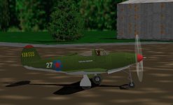
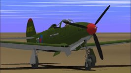
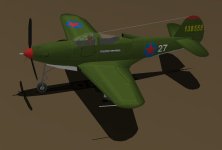
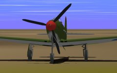
Now we have a Russian Pilot in an early Russian P39D-2 without wing-guns, on
which they thankfully overpainted the graffitti!
Now I´m calculating all the weight
they saved.
Parts count is still at 94%, leaving ample room for improvements, and bleeds are
are still cowering everywhere...
Cheers,
Aleatorylamp.
 

Attachments

  • Russian Pilot-.jpg
    Russian Pilot-.jpg
    50.6 KB · Views: 0
Hello Aleatorylamp,

I believe it is possible to get the Airacobra to fly reasonably well even with the correct Wing Angle of Incidence.
There are a LOT of factors that can affect this and I can tell you that I had to mess with most of the ones I know about to get mine to behave the way I wanted it to.
The level speed on mine is still a couple MPH lower than I would want but pretty correct according to "The Book".

I know my approach to "creating" an AIR file from the stock P51D and believe it works pretty well.
You seem to be working with a different process, so I don't really know enough about your current status to give useful advice when you run into problems except to tell you to check the basics and go through the steps I would follow.

This applies to both the AIR file and the MDL because I would have suggested going after the Bleeds first so that there are not so many Parts that might need to be changed if you find something is build in a non-optimal way.
So far, that is what I have been doing but I am also much less ambitious than you on this project.

In case you are wondering, the thing that is holding up my own visual model is that I found what I believe to be a discrepancy between drawings that I can't explain and it makes a difference of a couple inches.

I see you now have a Pilot. Pretty good progress.
If you want some Cyrillic writing on the side of the aeroplane, Google Translate can help.

- Ivan.
 
Hello Ivan,
Well, you know a LOT more than I do about .air files. That is evident every time I fly one of your planes - Me109e Trop, Warhawk, the corrections you did on the .air file for the AT-9 Jeep, whatever...

My approach to "creating" a new .air file from the P51d is much more primitive than yours, and I know very little of the more advanced way you go about it.

"My way" involves only basic and perhaps more obvious aspects (that´s why I tend to ask questions about things I don´t know or am uncertain about), putting in all the specification details, i.e. dimensions for fuselage wings and tail, the weights, the tanks, the fuel, adjusting the engine, propeller as far as I can deal with it, the landing gear, the scrape points, maybe the MOI´s, maybe the control effectiveness, and then I tend to leave other things I don´t understand alone, because that often creates havoc.

Anyway, now I´m going after the bleeds. Basically the model is just as complicated or uncomplicated as it was before, except for the canopy, because the basic elements are still the same, except for having a few pieces added to make their shapes better.

I´ll see if I can add some Cyrillic text somewhere! It´s always a good detail.
Cheers,
Aleatorylamp
 
Last edited:
Hello Ivan!
I think I solved a couple of things going through the .air file a bit more systematically this time, comparing some of the stabilty, control and maybe attitude parameters to entries in a couple of your .air files.
Why I hadn´t done so before, is a good question. Perhaps a case of not seeing the trees because of the forest, or the forest because of the trees... I suppose it´s just impossible for the brain to retain everything that has been picked up over the years without getting a memory expansion, or a new one, for that matter.

Regarding the engine being visible through the rear canopy, I further analysed some pictures, and saw that it varies. Some show what looks like the engine, and others show a surface with a box of equipment on it.

Anyway. Once I have the main bleeds licked and everything is more or less presentable, and IF you were to be interested, I could attach the model to a post, maybe even with the AFX. But, as I say, only if you are interested and/or have time, because I know you are busy enough with your own projects.

Cheers,
Aleatorylamp
 
Hello Aleatorylamp,

Sorry about not getting back to you sooner.
I have actually been quite busy with some research and discussions about the Airacobra and with non computer projects.
We also had some guests in town.

The Thunderbolt has also been a slight distraction from a research standpoint.

I believe you will care most about the Airacobra discussions.
I ran into a fellow on a forum that used to own a P-39D-2.... with a 37 mm cannon installation.
It seems like the references I was using were not correct. Some aircraft may have had the cannon replaced with a 20 mm in the field because early 37 mm guns were not reliable, but they were equipped with a 37 mm from the factory.....
Another fellow commented that the backfire screens on the Allison engines were typically removed in the field because of their effect on performance. Thus the performance test without the backfire screens installed was probably representative of the in-service configuration.
This also would mean that the critical altitude on my own P-39F is too low.

I guess that shows how reliable my "research" actually is.

The last known mistake (thus far) was that my scaling of Eric Johnson's P-39D was probably incorrect.
I still have not pinned down the details yet, but the aeroplane was probably not quite as long as I had thought.
The 30 feet 2 inch dimension is correct but the reference points were not correct.
The set of drawings really cannot fit together with ALL of them being accurate because they contradict each other.
I am also most likely going to switch to a different set of working drawings from those by Paul Matt.

You can post your project if you wish, but I won't look at it in detail until I have my own version of the AIR file closer to a finished state. If you really are done, why not release it? It would easily be the best one out in the CFS world.

- Ivan.
 
Progress Report

Hello Ivan,
A P-39D-2 must have been a nice thing for that fellow to be able to own!

Well then, that data would coincide with the comments that the 37mm gun was put back on the factory model after the -D1. Only 30 rounds, but great punch, and more weight in the nose, which was better. The cannon seem to have been pretty well interchangeable on-field, so that would perhaps account for both being seen on photos of the -D2 model.

I think I´d be inclined to stick to the 20mm gun on my extensively re-worked model, for playability reasons, unless of course I wouldn´t... I don´t know.

I have been very busy in the bleed-battle.
Some of the building-style on the original FS5 model, e.g. the top and bottom half-components for wings and wingroots, the several itterations of wing intakes amongst other things, were most probably work-arounds that worked at the time.

After the QBasic re-scaling job and correcting the aft fuselage angle, while I was putting in more parts to make everything rounder, I checked that different reference points were correctly placed as per the plans. I did notice small discrepancies here and there between different sets of drawings I was using, but I´m not particularly bothered.

The important discrepancy to be solved one was discovering the amount by which the belly had to be lowered, and that went fine. The aircraft looks quite correct, and thank you for your encouraging words on it for the upload!

Anyway, I rationalized construction, despite the irritating non-consistency of having parts built some as "regular" on the right, some on the left, with their mirrored "opposites" also sometimes on one side, and sometimes on the other.

The wing root is now in Body Main with slanted glue as well as the wing/fuselage glue templates, and seems to work. I am still working on the trailing edge parts though - it is quite obscure how that was meant.

I made different components with the top sides of the cockpit to glue them to the cockpit floor pieces, trying to stop these from bleeding through when viewed from underneath, forward or backward. It seems to work well.

Now, the only "bad" part is the exhaust, that bleeds through from below-aft. There seems nowhere to glue it to. If I split up the mid-fuselage component that´s glued to the wing-root,
I´ll have to split up the wing-roots as well, and that will bring out more worms though. I wonder...


I got all the wheel wells and doors working well, except for very momentary bleeds here and there. The long fwd wheel doors don´t help much there.

I´ll post some screenshots soon , as I´m not quite done yet. It´s coming along... and I got the .air file another little bit better, and it feels just right! Performance for full WEP (spec. 1550 Hp S.L.) is also as good as it gets, despite the usual CFS1 peaks resulting here and there.

P.S. There one unwanted peak of 382 mph at 10000 ft with 54.9 Hg and 1562 Hp, but trying to curb that will ruin everything else.
I don´t know if it is worthwhile or a bore to post the numbers for peak performances here. Probably not.

Well, now it´s the nose back on the grindstone!
Cheers,
Aleatorylamp
 
Last edited:
First, the good ones.

Hello again!
As promised, here are some pictures taken from good angles, to enjoy.
I´m still putting together the pictures of the bad sides, to post later.

Even if the good ones overshadow the bad ones, I´m not satisfied quite yet.

It´s more difficult that it seems - I must see to the propeller, the aft wing-root
and a large, lower wing-panel.

Cheers,
Aleatorylamp
 

Attachments

  • Pic-OK-2.jpg
    Pic-OK-2.jpg
    45.8 KB · Views: 0
  • Pic-OK-6.jpg
    Pic-OK-6.jpg
    28.4 KB · Views: 0
And now the bad ones

...and now the problems that still have to be worked on.
Cheers,
Aleatorylamp
Update: There´s an extra two: The pilot/nose-top bleed, as he is in Canopy High wing. I´ll have to get him out of there, or at least his torso... Then, the fore-wheelwell is misbehaving too, shining through the wheeldoo, the Brat!
...apart from the strange auto-arrangement of the pictures in the post.
We´ll get it licked though! ...said the optimist... :nevreness:

Cheers again...

Aleatorylamp
 

Attachments

  • Fault-1-prop.jpg
    Fault-1-prop.jpg
    39.4 KB · Views: 0
  • Fault-3-tail-low_aft wingrt.jpg
    Fault-3-tail-low_aft wingrt.jpg
    35.2 KB · Views: 0
Last edited:
Hello Aleatorylamp,

The P-39D-2 that we were discussing was a crashed and presumably stripped airframe.
I haven't asked him much about it so I really don't know its condition.

Your project looks pretty good so far.
I can see a couple details that aren't quite right, but that is nit picking.
I don't know that a new build model would be any better.

Even with the updated data on the P-39D-2, I am still continuing the P-39F and P-39K.
I was doing some work earlier today with reworking a P-39F profile drawing to use as a reference.
The drawing does not have Landing Gear, so at some point, I will need to edit the drawing to add those pieces.
I do not know the drawing is completely accurate, but it is close enough that I can build from it with reasonable confidence.

It will be interesting to compare our reworks of Eric Johnson's P-39D at some point, but I don't really want to do that until I have finished a few more things on my rework.
The bleeds on mine are not all gone either but I don't think I want to spend a lot more time on fixing those unless they will help me with figuring things out on my own project.

If I feel up to it tonight, I might do a bit more tuning for general handling and possibly edit the Moments of Inertia again.

- Ivan.
 
Hello Ivan,
I thought it could have been a flyable P-39D-2...

Yes, it will be interesting to compare our two models when they are done!
I still have to work out a better way of dealing with the cockpit area, but that´s part of the fun, and
it would be happening on a scratch-build too.

The drawings I´m using are by far much better than what was available for Mr. E.J. when he built his model. They are still around! ...but I threw them out as quickly as I could.

The other, better sets I found, all show small discrepancies, and this seems to be what you are working out at the moment. I went for what seemed most reliable, but it is difficult to say.

One thing I noticed was for example the cabin area: Those drawings seen from above, show a rather long parallel central section and rounded off ends, and others, with discrepancies elsewhere, show the rear cockpit section in a more elongated oval fashion, which seems more correct judging by the photos. I got it more or less in-between, fitting into AF99 possibilities.

Then the cockpit slants fore and aft, seen from the sides: I had a more curved "cockpit-base" areas there, but I had to make them straighter to make the "floor" feasible.

Anyway... let´s see how it goes on!
Cheers,
Aleatorylamp
 
Hello Aleatorylamp,

Actually whenever I work on a single engine fighter, the Cockpit Area is where I begin, so the planning and layout takes a lot of the potential bleeds into account.
Retro fitting a Cockpit is a bit more of a chore because other Components may need to be redesigned if the original author had not planned for Cockpit, Pilot and Glass as is the case here. I had not really wanted to go there, but the Transparent Canopy on your model looks nice enough that I think I should install one in my EJ Model also.

Are you still using the Paul Matt Drawings? Those came out in the 1960's with in the "Historical Aviation Album", so they were in existence even if they were not as easy to find as today.
I do have quite a bit of experience working with drawings that are not the best quality. A few of my early model suffer as a result: The Corsair, Thunderbolt, Hellcat, and my early Warhawk are ones that come to mind.
That is why I spend so much time in looking for and in editing drawings on more recent projects.

I have only been editing Profile drawings thus far, so the rear Canopy Glass has not yet become an issue.

- Ivan.
 
Feasible cockpit

Hello Ivan,
I did notice how you started your Lightning, I think it was, with the pilot´s head and then the canopy glass and frame, for the reasons you mention.

In this case it wasn´t too hard to fit a cabin floor to the existing opaque canopy component, changing that into a structure and then fitting that to the later modifications on the fuselage.
Now I´m just fighting bleeds...

As you know, the canopy is a top-half alpha transparency structure, but now in front and back sections to display the central thick frame part better. That´s why there is a longish vertical pale triangle on front part there, as it´s only possible to chop dome-structure ends vertically. The rear chop coincides because it´s vertical.

I haven´t had much time these days for the Airacobra due to some silly health issues, but I´m going to re-distribute the cockpit wall, frame, and floor parts.

The drawings I´m using are still the Paul Matt ones, which seemed to be the most accurate ones. There´s now sense in changing drawings now that everything is in place.

I had to sacrifice some of the curved slopes in the forward and rear cockpit area for obvious reasons - I had a concave floor with 8 parts... now only 4.

Inspecting the AT-9 Jeep cockpit more closely, I saw it hardly slopes up at the front, although there it has an instrument console, and the back is vertical, not slanted, but I´m going to try to follow build. The Aircobra also only has one crew member, not two, so it should really be easier.

At the moment, I´m wasting a lot of components having 4 floor sections glued to 4 components made of narrow top-cabin-wall parts to stop the floor-panel bleeds. That may be OK for the front and back cockpit slope, no doubt, as it includes the top metallic parts fore and aft of the canopy, but not for the 2 central floor panels.

So the parts are shaped correctly and good for AF99 to use, but I´ll try to distribute them more intelligently.

We´ll see!
Cheers,
Aleatorylamp
 
Hello Aleatorylamp,

I see you are still having fun with Eric Johnson's AFX.
I looked a bit more at it late last night and saw a few more bleeds I should have addressed.
Some of those were caused by my rework of the Flaps.
I don't know if my Canopy will be nearly as ambitious as yours. It will certainly need another texture file.
I might also need to rework the Flaps to be "Deployed" rather than "Retracted" because there are just too many limitations with the current arrangement.

In your Screenshot, I am seeing that the "spur" on the Pitot Tube appears to be missing. What Happened?

I was actually extremely busy last night.
I had planned to do some tuning for general handling and came across something that actually required that I revise my notes.
In addition, the spreadsheet that I had made up for plotting control response does not appear to be adequate.
(I actually should have figured this out long ago, but had not because the order in which the tuning was done made a difference.)
I had adjusted the Roll Rate and then adjusted the Control Response which affected the Roll Rate.
I have a theory as to how it works, but I will need to see if my theory as to how the numbers are calculated is reflected in the testing within the simulator.
I will also need to get a bit smarter in graphing with MS Excel.

Afterwards, I did some poking around with a Weights and Balances sheet that I have been using and finally figured out that I was misreading one of the numbers because the quality of the image was so poor. I had thought there was an error in calculation on the document but it turns out it was a combination of misreading one digit and a slight rounding issue.
The result is that I am now moving the CoG of the model just under 2 inches from where it was before.

This part sounds pretty simple, but that little tiny error reaches into many other places.
The DP file needed editing because the Gun Stations moved by a corresponding amount.
The Fuel Tanks also moved (only 1 inch though).
The Landing Gear contact points also moved about an inch.

The final result is that as of today, I have a Flight Model that handles like Garbage and probably also will need to adjust the level speeds yet again. That adjustment was expected but just not so soon after I last adjusted them.
I think I need to re-order my check list so that this doesn't happen on the next project.
Before that though, I need to edit my spreadsheets to predict how much some of those factors need to be adjusted.

- Ivan.
 
Hello Ivan,
Well, the fun continues, absolutely!
The main thing is that it´s going where I want, and that´s motivating. My iompression is that the shapes on the model are now quite close compared to those of the real plane, so I don´t think it will be worthwhile for me to change to another set of drawings.

Even though my transparent canopy is quite ambitious, as well as the whole modification of the aircraft, (it was my original intention anyway), your project is altogether much more ambitious as far as accuracy is concerned. It requires much more intricate research in all aspects, for which I wouldn´t have the insight for, to be able to identify correct data so well.

It definitely sounds like you are enjoying the progress you are making, despite the extra work involved in making re-adjustments in many different places to get everything right. Everything is of course interconnected.

I have started on the easy parts of the adjustments I still have to make on my visual model. I got the tail-fuselage vertices aligned, fitting a "V" shape to the end, so as to match the bottom of the rudder. and to make the base of the fin line up correctly with the fuselage component vertices. Now it all fits, and I got the texture into position as well. Very pleasing!

Things are going a bit slowly as there are other things I have to see to, but it´s coming along.

Next comes the aft wing-root, as you can see from the screenshot.
Never a dull moment!

Cheers,
Aleatorylamp

P.S. As regards the spur on the pitot tube, I should add something to it to re-instate it. It was only a 2-D part, and the sillouhette didn´t come out correctly as the angles were filled in on the graphic. I turned it into a hexago-cross-section structure for the moment, but I have to see how to get it better.
 
Last edited:
One more clean-up

Hello again,
The aft wing-roots, or rather fairings, are clean now too.
They are glued to the central fuselage component in Body Main (not in Wing-Low any longer), which created bleeds because the fuselage section under the main air intake was a separate component, not covered by the glue sequence.

By incorporating these parts into the main fuselage component, it´s fine now, even saving a component!
However, it involved hand-stretching the mid-fuselage texture backwards, and shrinking the tailcone.
That kind of thing usually makes me cringe, and the division is just down the centre of the red star,
but it does the trick...

Cheers,
Aleatorylamp
 

Attachments

  • Aft-wngrt.jpg
    Aft-wngrt.jpg
    47.4 KB · Views: 0
Hello Aleatorylamp,

Red Star == Krasnaya Zvezda or Красная звезда

I actually had not noticed the Wing Fillet bleed before.
Seems like you took care of it reasonably well.
You mentioned the Lower Wing Group.
I believe I removed everything from that Group very early in the correction process.
I simply could not get pieces to not bleed from some angle when there was something in that Group.
(Note that I didn't say it wasn't possible; I just said I could not do it.)

I suppose I should at least get a Transparent Canopy installed in my edited EJ P-39D.
The difference in your screenshots is quite amazing.

If you were working with a constant scaling factor, I would suggest that you use the same idea as I did for the camouflage pattern on the Kawasaki Ki 61, but that won't work if the scales do not match across different major adjacent pieces.
That would make having textures that extend over multiple Components much easier to draw. Matching them otherwise is a pain.

You might want to take another look at a typical Russian paint scheme.
I believe their style of insignia is a bit different than what you have currently.

I actually got nearly nothing done yesterday. There were too many real life issues to worry about.
I did manage the first check of the Control Response graph and the results are not nearly what I expected.
In other words, at least for the Elevator, what I am seeing doesn't seem like it should be happening (but of course it is).

Over the last few days, I also did a fair amount of reading (mostly on the Thunderbolt but some about the Airacobra as well) and it seems like a Russian P-39N or P-39Q might not be such a bad idea. Much of the data I am looking at is really for the P-39Q-1 anyway.
As a related note, I believe there is one more path I need to pursue as far as confirming the CoG location: The P-39 Design Analysis article from the 1940's. With the spreadsheets I have already put together, I believe I can actually make a very good estimate for the CoG of those models which I believe is more different than my almost 1 inch adjustment is taking into account.
That problem is actually a bit more difficult than it appears.

- Ivan.
 
Back
Top