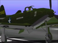
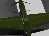
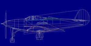
Analysing and modifying the AFX file with QBasic.

Hello Aleatorylamp,

Following your posts can be quite difficult at times. You tend to make a lot of edits to your posts.
What I saw this morning and what I see now are quite different, so I am not even sure what I should be responding to.

I figure if the drawings are accurate, I can do my best at representing the shape.
Most of the time, drawings are not so accurate. In this case, each set of drawings has its own problems but the Monografie set looks to be more accurate in general.

Aleatorylamp said:
I also notice the 2D pitot-tube spur shows up correctly on your display. Mine filled in the front-upper part. I think it´s the modern Open GL graphics that can´t do some old things that the old 3Dfx graphics were better at. The new ones obviously have better capacity for other things, although these would be unused in CFS...


The Pitot shows up correctly on my screenshots because I fixed it.
If you look closely, you will see that the shape has been changed as well.
As I have stated a few times before, our goals are different. I am not really trying to fix everything on this model. I am doing my best NOT to alter the shapes of the original unless I feel like I need to. If I fixed EVERYTHING that I saw as incorrect, there would be NOTHING left of the original. ....and it would still be someone else's model and not really mine.
That is why I am just using it to test ideas.

Aleatorylamp said:
Regarding the mid-fuselage/exhaust subject:
For the moment, have you kept the original wing-fairing / wheel-well distribution?
I remember you said that there didn´t seem to be much point in having the wings as upper and lower component halves, but that apparently didn´t include the fairings.


I rebuilt each Outer Wing into a single Component.
The Lower Wing Group proved to be the cause of many problems so I removed everything from it.
The Main Gear Wells had a lot of bleeds, so I rebuilt those and tacked them in place with Glue.
The Wing Fairings (Upper) are still in the Inner Wing Groups.
The Belly pieces include the underside of the Wing Fairings and seem to be a reasonable solution though they do have problems because they are in the Center Gear Group.

So far, I haven't used much Glue on the Fuselage pieces but that is likely to change very quickly when I put in the Cockpit pieces.
I actually may have to rebuild substantial parts of the Fuselage in order for the Pilot and Canopy to fit without bleeds and I really didn't want to do that.

- Ivan.
 
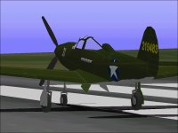
Transpare Canopy Updates

....Almost forgot:

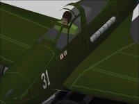
Here is an update for the status of the Transparent Canopy.
The first screenshot shows the Canopy Frame only.
The second screenshot shows my attempt at creating another pilot for the Airacobra.
The goofy thing is that to get the shapes the way I want them, the Parts expenditure was nearly the same as for my regular Pilot.
The Messerschmitt Pilot just did not seem to fit as nicely as I wanted.
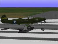
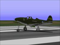
The third screenshot shows (more like Doesn't show) the Canopy Frame and Glass but hides the fact that there isn't even a Cockpit Floor. The P-39 is certainly not flyable in its current state.

- Ivan.
 

Attachments

  • P-39D_CFrame_Version2.jpg
    P-39D_CFrame_Version2.jpg
    50.2 KB · Views: 0
  • PilotTraining.jpg
    PilotTraining.jpg
    64.2 KB · Views: 0
  • NoGuts.jpg
    NoGuts.jpg
    49.1 KB · Views: 0
Hello Ivan,
Sorry about the edits to my posts, and I´ll try to reduce them. Instead of adding a comment in a separate post afterwards, I thought editing it would make it simpler, but I see it doesn´t, so I´ll change my habit.

OK on the pitot tube - the spike is now added. I´ll have to do the same to mine, even if I have to glue it on!

Your model is looking very clean, I must say! ...even if we have different objectives!

At the moment, what is left of the original model is just about only in the wings... and even if it is not completely my model, I don´t mind. Naming whose model I´ve re-worked, is no problem for me either.

When I was re-shaping the lower fuselage to make the curvature stonger, I saw that the lower fairing halves in Gear Centre and the wheel-wells weren´t doing such a good job there - the inner parts of the wells never went black. So, I joined the top and bottom fairing halves and grouped them differently.

Many things went better, especially with the extended gear seen from underneath, but brought along a chain of consequences that took a lot of fixing, one of which was that the exhaust could no longer be grouped where it was.

Now it seems fine, but depending on how it goes on inside the cockpit, I may revert the simpler, previous grouping. I´ll see.

At the moment I´ve rounded off and textured the exhaust component a bit better, so it won´t look like such an oblong. I know the benefit of this is debatable, but it does look a little more rounded off now, and with the shading on the textures, I´m trying to separate the images of each exhaust port a bit, so I expect it will have been worth while.

I´ll try and not edit this post later... I just did now to chage some prepositions.
Cheers,
Aleatorylamp
 
Last edited:
Hello Aleatorylamp,

The reason the edits were bothering me is because I browsed this thread with a mobile device fairly early in the morning to see if you had replied. I wasn't about to answer on the mobile though. Typing is very slow and screens are small.
When I came back later, the post was quite different and it any consideration about the earlier post wasn't useful any more.

I just finished doing some edits to the Nose section and the front of the Mid Fuselage section to eliminate an intermittent bleed that was happening there. There were a few polygons that were not even close to planar. That section will need to be cut up for a new Component for the Cockpit area.

I believe you must still be using the Mid Fuselage texture for your new Canopy Frame. I was getting the same kinds of patterns earlier.
It might be a good idea to copy that particular texture file to a new one. I called my new file Canopy.pcx but of course any name will do. If you do that and fill in the window areas of your new file with regular paint, the Canopy Frame will look less distracting.

My Canopy Frame seems to be amazingly expensive in terms of resources. Many Parts needed to be triangulated because they were displaying when they should not. Are you having the same problem? It appears that some of your Canopy Frame is visible out the front window.

- Ivan.
 
Hello Ivan,
I think you´re right about edits. As a post is editable for 6 hours, I thought it was more practical to include corrections or additions by editing it, instead of adding further small posts later, which would in turn also make it cumbersome to answer to.
Both ways have their drawbacks. The only really good solution is to space out posts more, with more concrete, final information, less speculation, and less volatile information, i.e. without writing about developments in "real time", as it were.

In my case, some nose section panels needed triangulating after splitting the cross-section from 8 into 12. Some were severely corkscrewed. The area under the cockpit also needed extra parts for the transition between round to flatter.

Initially, I filled in the grey on the original cockpit windows, but kept the drawn cockpit frame lines on the texture, as a reference, as in your case, but it is not definitive yet, and all that area needs texture corrections as yet. As the texture spread covers the whole fuselage and canopy area, this area is quite workable, so I thought it wouldn´t really matter if the canopy gets its own texture or not. Also, a new canopy texture would of course not necessarily imply a complete re-map of all fuselage textures.

The canopy frame component halves are tagged as "Collection", so as to be visible from inside, and so that the opposite side can be seen through the windows from outside.

The drawback is that there are bleeds through the metal from the opposite side, from the front and from the back, which could be stopped by tagging it "Smooth", at the cost of the opposite side being invisible, of course.

In fact, it´s not only the frame that bleeds through, it´s the pilot´s body as well. That´s what I meant when I said "depending on how it goes on inside the cockpit, I may revert the simpler, previous grouping.". Now, I don´t know if a different grouping of the lower mid-fuselage area will leave more room for some decent glue sequencing in the cockpit or not. I´m still procrastinating here too!

Right now, the Canopy Frame has 14 parts per half - I tried to keep pieces planar, so none needed triangulating in my case. Perhaps it is a bit more rudimentary, but it all fits for the moment.

Well, the Battle of the Bleeds rages on.
Cheers,
Aleatorylamp
 
New exhaust

Hello again,
Here´s a compound screenshot of the new exhaust, which could be argued
as looking better, although perhaps not necessary!
Anyway - it´s a bit more rounded off.
Cheers,
Aleatorylamp
 

Attachments

  • Exhaust.jpg
    Exhaust.jpg
    21.3 KB · Views: 0
Hello Aleatorylamp,

As usual, our purposes are different. One of my "Requirements" is that the original textures be altered as little as possible.
I want to be able to plug in any texture set that was done for the original EJ model and have it work.
That is why I am doing the Canopy Frame in another texture file.
Since that one did not exist in the original, I can alter it as much as I want.

I don't believe the original texture mapping is ideal and the naming of files is on the assumption that only one piece of the model inhabits each file. I believe I could do much better than that, but that gets into a texture remapping exercise which I hate.
I am already running into this problem with the Pilot.
I lifted the textures from the Me109E Trop even though the 3D model underneath is pretty different but there are enough alterations needed as to make the mapping job pretty tedious.... And I haven't even gotten to the Pilot's Shoulders yet.

There will be at least three (or four if you count the Interior Canopy Frame) items that still need to be textured, so it would be silly not to share the texture files between pieces.

Naming the File after a single piece of the model is misleading.
In the case of the Me109E, the Supercharger Intake shares the same file as the Pilot but the file is called Pilot.PCX....

Just as a comparison, my Canopy Frame has 23 Parts per side.
Actually each side only has 18 Parts, but the Left Component has 5 extra Right side Parts so there can be a slight overlap to avoid bleeds from inside the Cockpit.

Regarding edits to the model, I would strongly suggest that you review photographs of the real thing when working on pieces of the Aeroplane. Sometimes what looks reasonable in AF99 isn't reasonable when one considers how big the actual Part would be if scaled to real world dimensions. That applies to shapes as well.

Here are a few screenshots of my edits from last night.
The Canopy Glass has been removed so that the interior is more visible.
The Pilot's Head looks to be a bit too narrow still, and the fellow need to requisition a set of Goggles and a proper Uniform.
As a Company test pilot, he is fine, but Army regulations would need to be followed before this project is completed.

- Ivan.
 

Attachments

  • FamiliarPilot.jpg
    FamiliarPilot.jpg
    45.2 KB · Views: 0
  • PilotCloseUp.jpg
    PilotCloseUp.jpg
    36.8 KB · Views: 0
Last edited:
Hello Ivan,
Of course... our purposes are different. In my case I have to alter textures quite a lot because of the re-adjusted shapes and re-positioned, re-grouped elements, but that was to be expected.

I also not only look at different sets drawings all the time, but constantly look for different details on all possible photos iI can find. Incidentally, I found an interesting Russian article by one of the pilot trainers on how early Airacobras were crated over from England, inventoried, assembled and used for training, and later models were flown over from the U.S. I also read that they sent back some of the cannon, to use their own ShVAK 20 mm ones wqith which they were more familiar, and that one of the reasons they really liked the Airacobra was that after landing flip-over accidents the pilot could come out unscathed, as opposed to a lump of flesh as happened on other models. Howevcer, the article didn´t go into any technical details.

Back to my headache: The canopy-frame, pilot´s head and body, and cabin floor are still causing bleeds. This is because the cockpit is sunk into the fuselage a little, so the front and back parts bleed. Then, the "floor" pieces, together make quite a concave shape, so I had them glued to partial cabin components, which seemed OK, but wasn´t perfect.

I suppose it would be safe to assume that the canopy-frame would be in Canopy-High Wing. Initially I had the Pilot there too, so that the cockpit "floor" parts could be tagged as insignia-above, but that still created problems with the angular parts.

On the other hand, if the canopy were also in Body Main with everything else, perhaps that would allow a decent glue sequence with slanted triangles between canopy halves and the head.

Thus, I would like to ask you, only generally, about how you would plan, at least initially, to group the parts for your transparent canopy.

Cheers,
Aleatorylamp
 
Hello Aleatorylamp,

Aleatorylamp said:
Of course... our purposes are different. In my case I have to alter textures quite a lot because of the re-adjusted shapes and re-positioned, re-grouped elements, but that was to be expected.

As it turns out, I may need to redo some of the texturing myself. The existing textures don't line up well with the new Transparent Canopy pieces. I CAN adjust the pieces to fit the textures, but I can see a distortion problem if I choose to do that.

Aleatorylamp said:
I also not only look at different sets drawings all the time, but constantly look for different details on all possible photos iI can find. Incidentally, I found an interesting Russian article by one of the pilot trainers on how early Airacobras were crated over from England, inventoried, assembled and used for training, and later models were flown over from the U.S. I also read that they sent back some of the cannon, to use their own ShVAK 20 mm ones wqith which they were more familiar, and that one of the reasons they really liked the Airacobra was that after landing flip-over accidents the pilot could come out unscathed, as opposed to a lump of flesh as happened on other models. Howevcer, the article didn´t go into any technical details.

That must be a very interesting account. If you can flip a Nose Wheel Aircraft, then things must be bad.
If survivability in a Razorback Yak or Lavochkin is worse than the Airacobra when the aircraft flips, then life is REALLY bad....

I commented about the need to look at photographs because I noticed a couple errors in the Paul Matt drawings.
I actually included one of those errors in my own edits but now that I know about it, I will be sure not to include them in the actual project aeroplane.

I also noticed that the Canopy frame segments in your model appear to be much too narrow.
Look at the area of the Door and Door Frame.
There is both a Fuselage piece and a Door piece that come together.
My own estimate is that with two pieces coming together with a seam in the middle, the combined segment width is at least three or four inches which means it should be at least 0.25 feet across and probably much more.
Some of the frames appear to be much wider than that.

Aleatorylamp said:
Back to my headache: The canopy-frame, pilot´s head and body, and cabin floor are still causing bleeds. This is because the cockpit is sunk into the fuselage a little, so the front and back parts bleed.

I believe I am actually getting a pretty clean assembly with no obvious bleeds at this point. (Arrogant, aren't I?)

Aleatorylamp said:
I suppose it would be safe to assume that the canopy-frame would be in Canopy-High Wing. Initially I had the Pilot there too, so that the cockpit "floor" parts could be tagged as insignia-above, but that still created problems with the angular parts.

On the other hand, if the canopy were also in Body Main with everything else, perhaps that would allow a decent glue sequence with slanted triangles between canopy halves and the head.

Actually your assumption isn't "Safe". I actually have NOTHING in the Canopy / High Wing Group in my Assembly.
I am not really sure what you mean by "angular parts".
I found that my regular Glue sequence worked out pretty well with most of the major pieces in Body, Main Group.

Aleatorylamp said:
Thus, I would like to ask you, only generally, about how you would plan, at least initially, to group the parts for your transparent canopy.
[

If you are only looking for a "General" description, then perhaps you might want to quit reading at this point.
This description is about to get pretty detailed with illustrations.
.
.
.
.
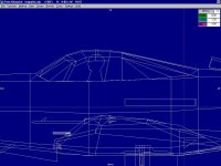
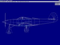
The First Screenshot shows the way that I sliced up the MidFuse Component into three pieces.
From the center section that I now call FuseMid, it is pretty obvious what was sliced off the front end and the back end.
The ends were sliced off into separate Components because each end had a section that created a concavity that was difficult to avoid. Note that this kind of concavity exists in just about all single seat Aeroplanes, so the treatment here is pretty similar.

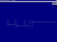
The Second Screenshot shows what each side of the Canopy Frame looks like. This Component is CFrameL which is the Left side Canopy Frame. Note that this Component extends past the mid line with one extra Part at each frame segment thus it overlaps the Right side which also extends past the center line.
Note that I have posted Screenshots in the past that have the left and right sides coloured differently to show the overlap, but I can't remember which project this was for. I tend to use this technique for just about every project.

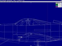
The Third Screenshot shows the GlueCFrameL Part which aligns with the Port side Cockpit sill on the bottom and the peak of the Canopy Frame at the top.

Hope this helps.

- Ivan.
 

Attachments

  • FuseMid_Component.jpg
    FuseMid_Component.jpg
    42.8 KB · Views: 0
  • CFrameL_Component.jpg
    CFrameL_Component.jpg
    18.6 KB · Views: 0
  • GlueCFrameL.jpg
    GlueCFrameL.jpg
    64.2 KB · Views: 0
  • QuarterView.jpg
    QuarterView.jpg
    51.4 KB · Views: 0
  • TopView.jpg
    TopView.jpg
    35.3 KB · Views: 0
Hello Ivan,
OK, very interesting! Thanks. Very explicit screenshots and descriptions.
Eliminating concavities by dividing the fuselage this way was one of the things I noticed would be necessary, and this re-arrangement was next on my list, after different other maneuevers of debatable benefit! It is also surprisingly simple, and accounts for the success you have had with it!

OK, I´ll study the matter and act accordingly, and also make the canopy spars wider!
By angular parts in the glue sequence I meant irregularly shaped triangular glue templates, placed at angles.

Very well!
Cheers,
Aleatorylamp
 
Phase 1: Nose component

Hello Ivan,
The new position of the division between the nose and mid-fuselage components did its job successfully. There is no longer any pilot or canopy frame interference through the metal in front of the windshield.
Here´s a blueprint screenshot - I still have to thicken some canopy-frame spars.


This would be the first part of the operation. I see you have an instrument console - at the moment I have the dashboard bitmap directly on the forward inclinded "floor" panel, but that can change!

Now for the second part, the mid fuselage, going aft up to the beginning of the aft-canopy slope:

If the mid-fuselage is a whole component from canopy-sill to the bottom, then the wing fairings can´t be glued to it in one piece, as they portrude aft. Neither will the glue sequence be able to include the exhausts. The Pilot, floor and canopy frame also need glue at the top, so it´s a bit difficult. Would it require further splitting up the mid-fuselage component?
For the moment it´s not working very well.

Of course... unless it is done like on the original model. Presumably you still have it this way:
Exhausts in Mid Wing R/L, upper Wing-Fairings in Inner Win Mid R/L, and lower Fairings in Wing Low R/L (correction: ...in Gear Centre), with the consequent issue of the wheel wells and their debatable display characteristics in Wing Low/LR and duplicated in Gear Centre.

Interestingly enough, the cockpit "floor" between the two canopy slopes is an entire part, which despite being slightly bent in a concave way, still displays correctly without disappearing.

Incidentally, in case you were to be interested, the .pdf article about the AiraCobra in Russia is here:

http://lend-lease.airforce.ru/english/articles/romanenko/p-39/
http://lend-lease.airforce.ru/english/articles/romanenko/p-39/part2.htm

The before-last paragraph of the second part mentions the virtues of the aircraft as per Russian pilots´opinions.

Cheers,
Aleatorylamp
 
Last edited:
Hello Aleatorylamp,

My Assembly sequence is much worse than yours because I am trying to retain the original texture layout.
The MidFuse Component was split into three Components as I described earlier:
FuseMidFor
FuseMid
and
FuseMidAft

The reason for this was that the Nose Component had a different texture and I could not add to that Component without having to remap the texture because it would have extended too far.
Along the same lines, I divided the TailCone Component into two with a new Component that only has the two bays that were removed from the original TailCone. Again, The TailCone had a different texture and I wanted to retain that.

At this point, I am finding that I am basically spending time refining and adjusting shapes for what I consider a throwaway model.
I probably have gotten as much as I ever will from working on the EJ AFX, so it will getting a lot less attention.
I still should not leave a patient on the operating table and I do want a model for comparison to my own project at some point, so I will at least fix the things I have broken with my modifications.

Along those lines, the Instrument Console will get adjusted a bit because the shape isn't really the way I think it should be and I was the one that put this in the model. The Flaps need fixed. I will probably leave the Exhausts alone even though they are pretty easy to fix.

Aleatorylamp said:
If the mid-fuselage is a whole component from canopy-sill to the bottom, then the wing fairings can´t be glued to it in one piece, as they portrude aft. Neither will the glue sequence be able to include the exhausts. The Pilot, floor and canopy frame also need glue at the top, so it´s a bit difficult. Would it require further splitting up the mid-fuselage component?
For the moment it´s not working very well.

Of course... unless it is done like on the original model. Presumably you still have it this way:
Exhausts in Mid Wing R/L, upper Wing-Fairings in Inner Win Mid R/L, and lower Fairings in Wing Low R/L (correction: ...in Gear Centre), with the consequent issue of the wheel wells and their debatable display characteristics in Wing Low/LR and duplicated in Gear Centre.


I wasn't really sure how I should respond to your statements here.
I believe you are forgetting the basics of how to use Glue in Aircraft Factory 99: Order Matters....
Try this sequence:

PilotHead
Glue
PilotShoulder
Glue
<I have a LOT more stuff here.>
CockpitFloor
Glue
FuseMid
Glue
FuseMidAft
Glue
FuseMidFor
Glue
TailFor
Glue
CFrameL
Glue
CFrameR
Glue
Exhaust
....

I think with this is enough that you can get the idea.
My actual sequence isn't quite the same but I have a lot more pieces in the sequence and I am also not going to bother with the Exhausts which are still in the Inner Wing Group.
If you want to see a much more difficult situation, look at the Supercharger Intake on my Kawasaki Ki 61 and figure how that can be made to work.....

I actually came across the site that hosts the links you posted but I was looking for cockpit photographs at the time and didn't read any of the stories.

As it turns out, I don't think I will be using the Paul Matt drawings even for a print reference.
I believe a different Monografie set is easier to clean up and use. It also happens to be for a P-39Q though....

- Ivan.
 
Hello Ivan,
Many thanks for your instructions.
Evidently there were a couple of things I didn´t quite understand in your post #149.

I thought that the components sliced-off the front and rear of the original Mid-fuselage component, would be stuck onto the Nose and Tail-fuselage sections, leaving a reduced-length mid-fuselage component, but I see now that this is obviously not the case.

OK, I understand what you are trying to do and why, and I can easily return to the old Nose Component and Texture, and include the front "slice" into the mid-fuselage sequence.

With the glue sequence you describe, it is obvious now that the exhausts are not in Wing Mid L/R, but incorporated into the glue-sequence covering the cockpit and mid-fuselage elements.

So, I may deduce from this, that my problem of trying to keep the new distribution of wing-fairings in Body-Main, glued to the lower mid fuselage would then be discarded, and it would be necessary to revert to the original distribution of having wing-fairings and wheel-wells in Gear Centre.

...unless of course the "...." at the end of your described glue sequence means that the wing-fairings are to be included at the end of this Body-Main glue-sequence. I´m not sure if the glue-sequence can cope with all this, but I´ll try it out.

This was precisely the reason for my question in the first place.

I don´t believe I was at all "forgetting the basics of how to use Glue in Aircraft Factory 99: Order Matters....".

I know Order Matters - but I also know that it is a matter of discovering exactly how to put that order together in AF99 in order to to achieve the results one is looking for.


I´ll see how it goes.
Cheers,
Aleatorylamp
 
Last edited:
Hello Aleatorylamp,

If you are reworking the textures, then you CAN put the sliced off segments onto the Nose and Tail.....
Well, Sort of.... You wil =l have to think of scaling changes if you do that.
The Problem is that the the sliced off segment at the back along with the forward segments of the Tail must live in the Body, Main Group or you are likely to have problems with bleeds with the Wing Fillets.
That is why I had to slice off a couple segments from the TailCone as well.

I kept the sections sliced from MidFuse as their own Components because they did not share textures with the Nose or Tail Components and I wanted to retail the original textures. My own project will be designed with these divisions worked out in advance and figuring out where the separations need to be is part of the benefit of working on this "throwaway" project.

There are enough different options possible for the Wing Fairings that I am not that concerned about making them work on this model yet.
I just believe it is necessary to put the Wing Fairings and Exhausts into the same Group and they will PROBABLY be in the Body, Main Group to avoid issues with interactions wit the underside.

You are right, the "Order Matters" comment was Not very nice.
I had the idea that there would be a lot more issues with this project than it appears that there are. (More Famous Last Words!)
So far, it looks to be more tedious than really difficult.
The general arrangements are looking very much like a cross between a Spitfire and a Bubbletop Thunderbolt!

The AIR file is actually proving to be the most difficult part thus far. I worked out a bunch more numbers last night and tonight I will see if things fit together.

- Ivan.
 
Last edited:
Quite amazing!

Hello Ivan,
Yes, your comment was very nice.
Now, to what extend I was forgetting the basics of AF99 glue sequencing, is debatable...

Anyway, the result is quite amazing!

It has worked, by simply fitting your sequence into what I already had!

I just incorporated your glue sequence into my Body-Main section, observing the necessary modifications to achieve the newly corrected order for the elements in your list: Pilot, floor, mid-fuselage, C-frame and exhausts.

For the moment, I didn´t change what I already had, just as an experiment, i.e. my newly modified Nose still including the "slice" cut off the forward mid-fuse section, and I kept the horizontal division of top and bottom mid-fuselage component halves, and the fuselage-tail sections. The exhausts this way still ended up glued to the top mid-fuse component half, and the bottom half continues successfully having the Wing-fairings glued to it, with wheel-wells also there.

Then, I also kept the aft-cabin upper section (on which the air-intake sits) which is separated from the fuselage tail and mid-fuselage sections.

The attached screenshot shows the perhaps somewhat outlandish way the mid-fuselage section is divided into its three components.


Glue-Sequencing is something that looks extremely simple and is completely amazing when it works.

Why it works, or how, is a different matter altogether, even though I know that in theory it is because it establishes an order for parts to be displayed. It is something I will never be able to completely visualize or understand.

OK on your comments on possible re-distributions of the mid-fuselage "slices"!

Now I will decide the best maneuever for the sliced-off sections with respect to the texture mapping. I may re-arrange them to improve scaling and distribution.

I also have to work on the canopy glass, which is not behaving itself yet because it is not included in the Glue Sequence yet - I think I´ll make components out of the structure so as to avoid the places it overlaps with the frame pieces.


Thanks a lot!
Cheers,
Aleatorylamp
 

Attachments

  • Amazing.jpg
    Amazing.jpg
    45.6 KB · Views: 0
Last edited:
Hello Aleatorylamp,

My apologies. My intended comment was that the "Order Matters" was NOT a nice thing to write.

I guess to me this Glue sequence thing is pretty easy now because just about every project I have done is a single engine fighter and this one is looking like it fits into the pattern pretty well thus far.

- Ivan.
 
Hello Ivan,
Yes, I gathered as much, and my reply was quite in line, though less incisive.
A cat is a cat, and can´t avoid its nature, and humans who have cats know that.

Anyway... A well-working glue sequence is great. It´s the pleasure of winning the Battle of the Bleeds, although there´s still a few more details to see to before it´s done.

I´d be curious to see how you would continue your version of the glue sequence towards the inclusion of wing-fairings in Body Main, although this may not happen if your model version meets your objectives without needing to be completed to that extent.

Cheers,

Aleatorylamp
 
OK, and No K.

Hello Ivan,
The main Cockpit bleed-battle (but for the cabin-glass) is OK, including a last-minute aft C-Frame spar interaction I was getting with the aft-cabin floor.

However, there´s one thing still Not OK: The same prop-geardoor interaction as before, as one you were having too some time ago, from a certain forward angle. I´ll have to revise the nose sequence again, which shouldn´t be too difficult.

Once that is done, it will be the turn of the canopy-glass component and texture fine-adjustments -
I´ve also just thickened the C-frame spars.
I don´t think it will be too long to finish the model now.
Cheers,
Aleatorylamp
 
Hello Aleatorylamp,

Humans should be as smart as Cats. We had a pair of Cat many years ago.
My Children were talking about them about two days ago, so they still remember.

My plan as always was to try out a few things to test ideas for my own project and fix the things I break along the way.
There was never the intent of fixing everything that is wrong with this model.
I suppose you figured out why I was building a Transparent Canopy.
Part of it was because it looked so nice on your model. Part of it was to test an assembly sequence.
Even the sequence that I recommended to you has issues.
You probably don't see them yet because you don't have quite as many pieces in place as I do, but there ARE issues when more pieces are added.

Where you are chasing bleeds at the moment isn't quite where I am chasing bleeds.
The Nose Gear bleed needs a lot more testing, but since it was there before I started, I will probably not attempt to address it until I have fixed what I broke.

- Ivan.
 
Hello, Ivan!
Cats are smarter. They got the Egyptians to treat them as gods, and that was long ago. In the Dark Ages cats had a hard time however. The ruling class installed witch hunts and inquisition, with the resulting anti-cat paranoia. Cats would have stopped the Bubonic Plague, but they were being killed off. Then, the same ruling class decimated native tribes and their Chaman wisdom throughout the whole New World, so now we have modern medicine to kill us off slowly while we continue being good slaves spending our money on medicines, but that´s getting a bit off the topic of cats...

Anyway... From what you are saying, when I finish the canopy-glass component, for the moment at least, I´ll leave that area as it is, and resume the bleed-battle with the propeller in the under-nose area.

Somehow, the more or less fine-working propeller and nose-gear animations don´t get on with each other. There is a nasty case of Glue-Cure Immunity between Gear-Nose and Nose groupings, and there isn´t a Nose/Gear-Nose Glue Template.

The solution may require everything to exist within the Nose Group. The body cringes at the thought. For a start, I´ll have to get the forward "slice" out of the Nose component again, to free the glued dashboard from the nose area. Let´s see what I can manage with this idea.

After that, I may even leave the Instrument Console and the Tool-Box behind the pilot for the imagination!
Cheers,
Aleatorylamp
 
Back
Top