B-S Model 75 - the visual model

aleatorylamp

Charter Member
Hello all!
This thread will be dedicated to building a Boeing Stearman-75 model with AF99 and some slight SCASMing for the cockpit view.

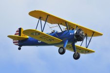
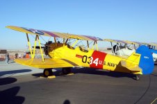
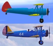
I will endeavor to supply an ARMY and a NAVY model, in colour schemes similar to those on the attached pictures.

This historical aircraft model boasts one of the highest numbers built, and thousands of pilots have been trained in them. Its sturdy construction has resulted in over half of the total produced units still to be flying nowadays, which is extremely impressive for an early 30´s design.

The flying characteristics of this notably large biplane are famous for being stable and quite forgiving, yet quite tricky on the ground, and the aircraft are renowned for its acrobatics, even those equipped with standard engines. Many were re-engined with twice the standard power or more, after a great number of surplus Stearmans became available to the general public after the war.

It was also widely used as a crop-duster, and some were even armed with machine guns and bombs, and sold to South American and African countries!


So... off we go!
Cheers,

Aleatorylamp
 

Attachments

  • Boeing-Stearman ARMY.jpg
    Boeing-Stearman ARMY.jpg
    65.5 KB · Views: 0
  • Boeing-Stearman NAVY.jpg
    Boeing-Stearman NAVY.jpg
    68.7 KB · Views: 1
Stearman-75 Work in Progress model

Hello all!
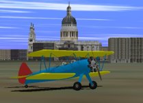
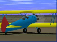
I´ve been rather busy building this week, and here is a first provisional trial model, just to get a general impression and feel of the shapes. Also, to try it out in the air, should anyone be so inclined!

It is the Army Trainer version with the Continental R-670 engine, in blue-yellow colour scheme, as yet incomplete, just for fun. The only textured parts are the wheels - texture is provisional too!

1-Engine, cabin area and the wingtips are components, in a more-or-less advanced stage, except for the dark covering panels, they are not glued properly yet. The engine still needs an exhaust ring in the rear part, and a pipe.
2-Wings and fuselage are as yet provisional structures, and will be made into components shortly.
3-Gear-struts, Wing-struts, tail-fin and tailplanes are all provisional 2D planes, and will be built out in due course, or course!

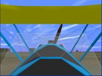
Provisional Panel with Gauge distribution loosely based of a photograph, plus some extra convenient gauges, and an Autopilot.

Cheers,
Aleatorylamp
 

Attachments

  • Army Stearman.jpg
    Army Stearman.jpg
    32.1 KB · Views: 3
Engine and central fuselage shapes

Hello Folks,
A short note on present engine and cockpit shapes:

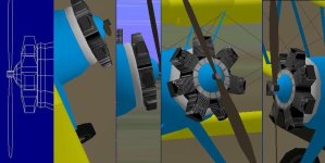
The main engine component, not counting valves or front cone and axel structures, for the moment only has 30 parts. The square-shaped cylinders prevent any texturing for cooling fin lines, as the front and back are flat, star-shaped surfaces,making the texture bleed into the between-cylinder spaces.
This should however be corrected as soon as cylinders are hexagonal, and the front and back flat cylinder-surfaces no longer exist. So, engine texturing is planned!

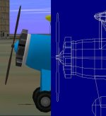
Then, the cabin component parts fit the provisional round fuselage shape. In the future, cockpits will be narrower because the general fuselage shape is narrower at the top, and the bottom a bit fatter - in fact, the fuselage bottom surface is flat in the lower wing wing (hence the space at wing-roots at present). All this will come in due course, as soon as the central lower fuselage section no longer a structure.

I like working with a complete general shape of the model, so I can get an overall impression while I´m building. This way, sections I haven´t started working on, all remain as template-shapes, either 2D or 3D Structures until their turn comes. I know this is not the more orthodox procedure followed by most modellers, who usually model with progressively finished sections.

Anyway, more later, as things take shape.
Cheers,
Aleatorylamp
 
...busy building, indeed.
and you're off to a great start.
i look forward to watching your progress.
have fun
 
Hello Smilo,
Yes, thanks, it´s going fun and nicely!

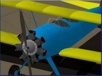
It worked! The engine now has hexagonal cylinders, and allows texturing - now it needs a decent texture, though! Including the myriad of between-cylinder covers, there are 65 parts in the main engine component, apart from the front cone and axel. Parts count is still at a low 97%, so I should be able to keep the complicated engine without having to go for the previous simpler one. We shall see.

The hexagonal shape made the pushrods stand out too far, but I was also able to bend them back a bit without having to make them into individual parts. Also, they won´t be in the engine texture, which looks a bit better perhaps. I also managed to curb Cylinder-bleeds a lot by having outward facing insignia-lids on them.

So, it´s going quite well, and now we´re off to the farmer´s market.
A bit of a cloudy day today... it will be nice for a walk in the country.

Update - Correction:
I think I goofed on the frontal pushrods for the Continental R-670 Series engine - they were at the rear!
Only Lycoming and the Jacobs radials had them at the front. A pity, because I thought they looked rather good.
Never mind...

Cheers,
Aleatorylamp
 
Last edited:
Cylinder shape

Hello Folks!

Although the texture-bleeds into the space between cylinders was solved by making hexagonal cylinders, this made them look even narrower, and the already too wide gap between the cylinders at the base looked even larger.

The Continental 7-cylinder radial cylinders are wider than the ones the on the model upto now, so, widening the cylinders was vital to correct the engine shape. However, as they ended up closer together, this increased cylinder-wall transparencies from side-views.

An experiment with octogonal cylinders proved to be even worse in this aspect. A thought on the octogonal-cylindered engine would be to perhaps have front and rear facing engine halves...

Hexagonal or octogonal cylinders did not look right either, because of the rocker boxes on the real engine.
Thus, square-shaped cylinders would be more correct after all! So... it´s back to the square cylinders.
The texture bleeding into the spaces on these was solved by separating the forward facing cylinder surface from the star-shaped front and rear - an easy fix to that problem!

Then I experimented further, with cylinders wider at the head than at the base, as the real engine has bigger cooling fins at the cylinder heads. Also, the real engine has a left portrusion on each cylinder. However, trying to shape these features on the engine not look convincing at all, both on hexagonal and on square-shaped cylinders, and of course only added to the bleed problems.

As a result, I´m afraid at least for the moment, it will be necessary is to stick to simple, square-shaped cylinders, albeit somewhat wider, and of course textured.

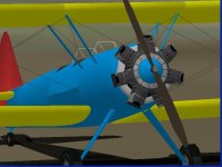
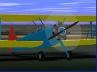
Here´s a screenshot of the engine - I´m trying to get the texture better so that there´s a grey band on the cylinderheads for the rocker boxes, and not all black. I might also make the propeller a little wider at the base, come to think of it!

Cheers,
Aleatorylamp
 

Attachments

  • radial-7.jpg
    radial-7.jpg
    49.7 KB · Views: 3
Possible improvement

Hello all!
Studying the Continental engine shape to best reflect its shape on the model, slanting the front and back cylinder surfaces a bit may improve the visual impression.
Here´s a compound screenshot - I have the feeling the effect is better.

I´ve also included the exhaust ring behind the engine, and the main exhaust p¡pe on the right of the ring will soon follow, but I´m not sure how possible cylinder-to-exhaust-ring pipe sections will come through, though, so perhaps they are better left out. Nevertheless, I´ll give it a try and see what happens.
Cheers,
Aleatorylamp
 

Attachments

  • engine-slant-2.jpg
    engine-slant-2.jpg
    57.5 KB · Views: 3
Hello again,
Here´s a comparison with a photo, just to check if the engine is better like this, i.e. cylinders slanted fore and aft, or with square cylinders.
...or maybe just slanting the front of the cylinders is better, like on the other screenshot added?
Cheers,
Aleatorylamp
 

Attachments

  • No44-.jpg
    No44-.jpg
    38.6 KB · Views: 0
  • Cyl-slant.jpg
    Cyl-slant.jpg
    38.8 KB · Views: 0
Last edited:
Hello Smilo,
The more I look at it, I think so too, thanks.
The cooling fin lines are almost there.
Next is the exhaust pipe on the right.
Tail surfaces and all struts are 3D now, and as soon as I
get something else done, I don´t know what yet...
I´ll post an updated model.
Cheers,
Aleatorylamp
 

Attachments

  • progress.jpg
    progress.jpg
    50.5 KB · Views: 3
Idea for the throttle gauge on the panel

Good morning folks!
I just had an idea for the throttle lever on the main panel, to make it easier to use:
I could alter the bitmap of one of the default CFS throttle gauges with conveniently
placed marks, to indicate the following:

> 1-minute (105%) max. take-off and climb power, at full 100% throttle lever position.
> 5-minute (100%) max. power at 96% throttle lever position.
> Max. continuous power at 91% throttle lever position.

The marks on the throttle gauge would be precisely placed using the Beckwith gauge stack.

This way, using F4 and F3, simmers can check the desired throttle lever position they
want. It would be better and more correct than just using the "0" and "9" keys because
this limits the selection to 100% and 90%.

Of course, one could simply put a "Minicontrols" gauge on the panel, but I feel it wouldn´t
be as practical.

Update: Bitmap alterations would involve only throttle and perhaps mixture levers, but not pitch control.
In order to avoid having to repeat a complete series of gauges in any of the default CFS1 sets, there are 2 choices in the FSFS gauge sets:
a) Fix up gauge bitmaps in FSFS Lear_45 .thrust_levers.1.gau, which only has a throttle lever.
This would be the "cleanest "option.
b) Fix up gauge bitmaps of FSFS Generic.controls.1.gau, erasing the central propeller pitch control lever.
However, this would leave a wide gap between the black throttle and red mixture levers.

Thus, for aesthetic reasons, I´d prefer going for the first choice.
Mixture could be controlled with kestrokes CTRL-SHIFT F1 to F4.
Would this be a good idea for simmers?

Cheers

Aleatorylamp
 
Last edited:
Hello again,
Another Idea would be putting in the extra 1-minute power as WEP, which in a way is what it really was, so I haven´t decided yet. The difficulty in this case is keeping normal power the same, so that the WEP implementation doesn´t increase it.
As WEP, abuse of the little extra power could be made to produce some damage - either to a minor degree, just losing the extra power, or on the other hand, effectively ruining the engine to leave it at a clattering wreck, incapable of producing more than half its power. The latter would be quite realistic, I expect... but maybe a bit drastic and ruthless for a game.

Update: After a few trials with the WEP option, normal performance is almost identical as before at all altitudes, and the little extra power is fine at S.L.
Higher up it is slightly high, but acceptable, and can be adjusted. So, it looks very promising indeed!


Choices, choices...
Cheers,
Aleatorylamp
 
Last edited:
WEP viable for 5% extra power.

Good afternoon, Folks!
Well, the adjustments were successful, and WEP is definitely a viable option for the 5% extra momentary power.

In my opinion, it would be a "cleaner" solution than leaving it within the normal throttle-lever travel. The reference markings on the throttle-gauge bitmap I had suggested yesterday wouldn´t be needed - although I did experiment with them and they worked.

Not that momentary 5% extra power is anything to be jumping around with joy and cheering about - it is only about 12 Hp, and at sea-level accounts for only 2.5 mph. However, the real plane did have it available for take-off and climb, so its use on the CFS model is justified.

As regards the method by which it is to be implemented, this is of course a matter of opinion, so I´m open to suggestions.

Cheers,
Aleatorylamp
 
WIP Model Version No. 2

Hello Folks!
I hope you are all well and have had a good, relaxing weekend! I have been quite busy again, and have made some progress on the visual model.

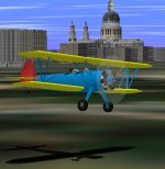
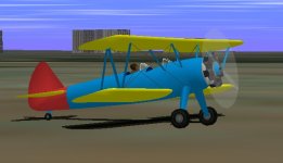
Attached is the SECOND Work-in-Progress version of the 1934 ARMY Boeing-Stearman-75 Trainer model, in blue-yellow colour scheme, as an opportunity to have a look at the progress made, and perhaps to try it out should anyone be so inclined. As eye-candy, there are also a couple of screenshots.

The main improvement is the engine and that the wings now join the fuselage component correctly! A difficult part was the semi-circular cut-out on the top wing above the pilot´s head, as it made a few concavities, but incorporating the left and right aft parts of the cutout into the main top-wing sections eliminated the disappearing borders.

Parts count is still at a very modest 87.3%.

1- Engine, Wings, tailplane, cockpit area and lower fuselage are now advanced components.
2- Nose and tail-fuselage, and fin are structures, and fuselage top sections are top-half structures.
3- Landing-gear struts and Wing struts are 3D components now.

Work which is to be done as yet:
1- The top-fuselage structure cross-section still has to be made a bit more "pointed", i.e. narrower, like the top half of an egg, with corresponding narrowing of the cockpits. This will expectedly improve the visual division between the top-half fuselage structures and the bottom half fuselage components.
2- Textures
3- General check for hairline cracks.

Flying the model:
Normal Throttle lever travel goes upto 220 Hp maximum rated S.L. power.
For take-off and climb, 105% max. full throttle 232 Hp power is available using Methanol-Alcohol Option-2 WEP (F10) for a limited period of time. Abuse will lead to engine damage involving the loss of the extra power.

As before, there is a provisional Panel, but this time it includes a custom throttle gauge, with a modded bitmap from the FSFS Lear45.thrust.1.gau throttle gauge. As before, it has a gauge distribution loosely based of a photograph, plus some extra convenient gauges, and an Autopilot.
Stearman Panel bitmap by Hugo Scanavino.

Any suggestions will of course be very welcome, (thanks in advance)!
Cheers,
Aleatorylamp
 

Attachments

  • WIP-2-1.jpg
    WIP-2-1.jpg
    46.5 KB · Views: 0
  • WIP-2-2.jpg
    WIP-2-2.jpg
    44.8 KB · Views: 0
  • WIP-2-3.jpg
    WIP-2-3.jpg
    34.1 KB · Views: 0
Tail section better

Hello all,
Now the different top-half fuselage structures have been turned into sections absorbed into the various fuselage components, giving smoother results as far as surfaces go.

Parts Count has gone all the way down to 81.1% with the elimination of all those fuselage top-half structures, and there are still 7 free components left over for any necessary enhancements. I wonder...
Of course it would be nice to get a better shape for the charismatic cylinderheads on the engine, but how to go about in an effective way requires a lot of thought.

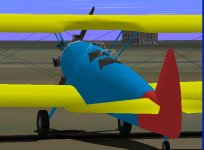
The two cockpits are also a little narrower, and now I´ve re-worked the lower rudder, which is now a part of the fuselage-tail component - this way the whole tail section is better shaped and cleaner.

Here´s a rear-view pic showing the tail area.

Now I´ll see to the windscreens.

Cheers,

Aleatorylamp
 

Attachments

  • tailfus.jpg
    tailfus.jpg
    40.3 KB · Views: 3
Last edited:
WIP-3 Attached.

Hello Smilo,
I hope you and yours are well.

Why indeed not attach WIP-3? Of course, gladly!
Here it is, with some eye-candy just for fun.
Thanks for your enthusiasm!

Progress since WIP-2:
1-The whole fuselage top section is now all done in components.
Note: Wing-Supporting Fuselage struts as yet not adjusted to the fuselage properly.
2-Further adjusted cockpit areas, with glass on the windscreens.
Note: Windscreen struts is in lines and glass is as yet in a whole component,
hence the bleeds - which will be seen to!
3-Upper tailfin is the only top-half fuselage structure.
4-Lower rudder is part of the tail-fuselage component - so it´s all in red.
5-Tailwheel still needs glue...
6-Pilot sitting in rear cockpit.
7-Parts Count is still at 95.3%, and there are only 3 free components left.

Shall we put in a student pilot? Head and torso are 2 structures, and there´s ample parts left.
I could make the head turn with the rudder...

The only textures are on engine, pilot and wheels.

If you like, I can attach AFX - I haven´t done so because it´s probably not needed yet.

Let me know what you think of the 105% top-max. power implemented as WEP. You have 232 Hp with 126.7 mph instead of 220 Hp, and 124.2 mph at S.L. for about 5 minutes. Climb is a little better too. We can decide if this is OK, or if it is better to have it included in the normal throttle-lever travel.
Note: The .rtf text document included with the WIP-3 aircraft relative to the throttle positions is not the correct one because it applies to the non-WEP equipped version. The correct doc. is included in the previous WIP-2 Version.

Cheers,
Aleatorylamp
 

Attachments

  • WIP3-3.jpg
    WIP3-3.jpg
    33.5 KB · Views: 0
  • WIP3-2.jpg
    WIP3-2.jpg
    31.6 KB · Views: 0
  • Wip3-1.jpg
    Wip3-1.jpg
    46.5 KB · Views: 0
thank you, Stephan,
all is as well as can be expected.
we take our small victories
when and where they present themselves.

i've downloaded the WIP3
and will try to have a look at her
today...in between chores.

have a good weekend
 
Some more progress

Hello Smilo,
A small victory is a definitely a victory - one step at a time. The best of luck!

No hurry with trying out WIP-3 - it should also be fun.

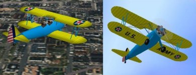
I´ve decided to make the WIP model less boring now, so I´ve adapted some very good textures that a friend, Udo Entenmann, made ages ago for a rather quaint and obscure Navy Curtiss Wright CA-1, also known as the Courtney Amphibian. Very few of these were produced, apparently only 3, but one seems to have been presented to the Navy for evaluation purposes, so we made a version with yellow wings and the old military star emblem that is also on the military Stearman´s wings. It was quite easy to adapt, although the lettering isn´t perfect yet, and the fuselage is as yet untextured.
However, it is slowly getting the look a little bit more!


Unfortunately the textures have also evidenced a bit of a concave image display problem with the cut-out borders in the wing above the pilot´s head, which has as yet to be dealt with.

I also managed to convince a student pilot to join the fun, and he´s riding in the front cockpit. Parts count only went up to 105.5 % with the extra crew member.
After I fix a few more things I´ll upload a WIP-4 next week - and fuselage and struts will also be textured!
Here are two views. Now one can say it´s a trainer...
Cheers,
Aleatorylamp
 

Attachments

  • Trainer-.jpg
    Trainer-.jpg
    54.4 KB · Views: 3
Back
Top