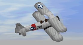
B-S Model 75 - the visual model

Hello Aleatorylamp,

I am glad you found the work on the exposed cylinder radial engine useful.
This critical assembly sequence idea was pretty much what I had been intending all along which is why I was confident it could be done in one or two Components.
I am somewhat surprised though that even with the pushrods, the exposed cylinder radial only costs two Components.
A typical cowled radial in one of my projects normally costs three Components to be bleed free.

I also saw the tail wheel bleed through the aft fuselage but thought it was just another piece of equipment that was supposed to be there.
I haven't followed your recent developments very closely but did you represent the stagger of the pushrods?
It would not be shown in a 2D texture, but pushrods to each cylinder do not enter the crankcase / gear housing in exactly the same alignment because they operate off of different cam drives from the crankshaft.

Incidentally, I just downloaded an overhaul manual for the Continental W-670 a few minutes ago. It probably has more detail than either of us needs for a CFS project.
I found the manual because I was exploring a forum and someone requested technical information on a W-670 removed from a landing craft and that was used for show on a test stand.
The unfortunate thing is that he apparently "Hydraulic-ed" the engine years ago probably from some oil that was pooled in an intake passage. I have not had a chance to go through the manual yet.

Anna Honey is in Switzerland at the moment, so I better go start making dinner. I spoke to her about three hours ago.

- Ivan.
 
Hello Ivan,
I experimented with left and right engine component halves for the cylinder area,
but found no significant improvement, so I discarded that.

As far as components go, there are the two you mention - one for the pushrods
and one for the cylinders including the central crank-case.
If cowled, I suppose three components would be needed.

Anyway, apart from the 2 components, there is
a) the exhaust ring structure behind, containing one exhaust pipe component
slanting down and backwards underneath,

b) a round crank-case "slice" structure in front, between the cylinders and the
pushrod-base, to prevent bleeds with the pushrods and the front of the engine, and
c) the dome-shaped frontal crank-case structure in front of the pushrods.

It took a while to figure out where to cut the slice stgructures and glue them, but they
were all added nicely
into the simpler sequence that the 7-cylinder engine has.

I didn´t experiment with the frontal exhaust collector ring of the Lycoming R-680-4.

Then, the Continental R-670-4 model only has one component for cylinders and central
crankcase, because the pushrods are hidden behind the engine and don´t show, and
there is one structure fewer.

The exhaust ring structure behind that with the exhaust component on the right side,
and the round dome shaped crankcase structure in front.

Looking at photographs of the R-680-11, I didn´t notice any stagger.
All the pushrods seemed symmetrical, so that´s how they went onto the model engine.

I also found the detailed manual for the W-670 engine you mention.
It even specifies all the spare part reference numbers!
The technical diagram shows all the bits and pieces inside, including the cogs that
drive the cams for the pushrods. Very interesting!

The whole radial engine concept is interesting in itself - how to pack a tremendous
number of horses into such a short space!
Good for Sherman Tanks too, and apparently landing craft as well, from what you say!

Cheers,
Aleatorylamp
 
Hello Aleatorylamp,

I was actually thinking more of fore and aft engine Components because the extra Parts for a 9 cylinder engine might exceed the limit for a single Component.

I had been wondering why the exhaust collector ring was such a different colour from the actual exhaust pipe.
Were these pieces plated or something?

Aleatorylamp said:
Looking at photographs of the R-680-11, I didn´t notice any stagger.
All the pushrods seemed symmetrical, so that´s how they went onto the model engine.

If you check closely on the top cylinder, you will find that the bottom of the port pushrod is just a bit further forward than the starboard one. As you pointed out, it isn't all that obvious from many views, so perhaps it is not such a big deal.

Personally, I don't know what these engines were used for but I believe the owner claimed it came from a landing craft.
Reading through the suggestions for diagnosing the failure was interesting.

Gotta go clean up after dinner again.....

- Ivan.
 
Rusty exhaust

Hello Ivan,
I see. A free component for a rear engine half would of course have been beneficial on the 9-cyl engine. Because the cylinders are closer together, it DOES have a slight, momentary rear cylinder panel interference when viewed from the side-front, but it´s hardly noticeable, and there isn´t a free component anyway, so...

OK, so the port pushrod on the top cylinder is further forwards, and going round successively to the other cylinders, the distance probably being equivalent to the thickness of one rod shroud. It could have been done by placing the stardoard pushrod shroud base closer to the cylinders, within the area of the engine housing "slice" structure there, and would have just been noticeable, but I´d say it´s a minor issue.

The exhaust pipe is a different colour because of the rust. The rest of the exhaust collector ring is underneath the narrow, metallic coloured area just behind the engine, which isn´t rusty.

The 225 Hp Lycoming (which I didn´t build) has a front collector ring behind the propeller, and the whole ring would be coloured in rust, without the metallic coloured part behind the engine.


Some acrobatic models have chromed exhaust pipes and frontal collector rings, but that would have been too expensive for a military trainer.

Cheers,
Aleatorylamp
 
Last edited:
Hello Folks,

I have just uploaded new textures for the 280 Hp Silver-grey Stearman PT-13B model.

The Star and Bar emblem was missing on red band on the fuselage sides next to registration
number 721, and the bars were missing on the stars on the wings.

This has now thakfully been very nicely corrected by Udo Entenmann.

As soon as Rami authorizes the upload, the new textures will be available in the library under the following link:

http://www.sim-outhouse.com/sohforums/local_links.php?action=jump&catid=20&id=23539

Enjoy! (and sorry for the bother...!)
Cheers,
Aleatorylamp
 

Attachments

  • PT13silver98.jpg
    PT13silver98.jpg
    47.5 KB · Views: 1
Hello Smilo,
Well, the bother of having completely overlooked the correct type of markings which were staring at me in the face from the 3 available colour photos!!
That existing, beautifully restored plane, which often appears at air shows, incidentally, has 7-cylinder, 225 Hp Continental engines because of FAA regulations, but originally, the serial number corresponds to one of the 257 units that were equipped with 9-cyl 280 Hp Lycomings due to a shortage of the proper engines that lasted a few months.
Anyway...
Cheers,
Aleatorylamp
 
Back
Top