B-S Model 75 - the visual model

Possible Military 280 Hp version?

Hello all, Hello Smilo,
I made a mistake before - the possible military 280Hp version, as argumented on the old Stearman thread, would not be for a Navy version, but for an Army Corps one. The Navy never had non-standard ones.

Two or three sources not only plausibly mention the existence of 255 units manufactured 1940-41 with the more powerful engine and designated as PT-13B, but also quote the exact production serial numbers of the aircraft produced with this engine. Also mentioned, are 6 Army Corps units of the PT-13A type that were re-engined with 280Hp engines and re-designated PT-13C.

Seemingly, the installation of this engine in the production line, coincided with a serious shortage of the normal engines used for this aircraft.

Now, in CFS1, using the current Stearman 16-degree pitch propeller and .air file, and entering the engine parameters of the 280 Hp Lycoming R-680-11 for the same airframe, the sea-level top speed that comes out with no further alterations is 135 mph!

This is curious, because it is the same top speed that seems to be erroneously quoted by several sources for the normal 220-225 Hp military versions, which should be 124 mph. So obviously there is something behind this error.

Anyway, it will be impossible to find a historically correct registration number corresponding to an Army Corps Stearman motorized with the stronger engine, because there were no official specifications to the production of these units. They seem to have been disguised as normal ones, with the exception of the strange 135 mph top speed that often crops up.

So, if I were to provide a more powerful Army Corps Stearman, the registration would have to be a fictitious one. On the other hand, given that a more powerful acrobatic Stearman is planned anyway, a more powerful military version might not be required. However, should anyone be interested in one, I would of course supply it!

Cheers,
Aleatorylamp
 
she's very nice, Stephan.
thank you very much.
on one hand, i say,
sure, go for it.
on the other, i say, why bother?
who will notice a few mph increase?
as for myself, i am more than happy
with what i have right now.
but, of course, the final decision is yours.
 
Hello Smilo,
I´m glad you like it!
The next hurdle will be how the 9 cylinders allow themselves to be displayed,
and actually, if everything turns out fine with the planned "Super Stearman",
there would really be no need for a hotter military version.

The increase to 135 mph is not really all that much anyway. The wooden
propeller did have its limitarions. A CV prop, even with the same engine and giving
300 Hp raised top speed already to 144 mph, which was quite a bit more.

Now, with the acrobatic version, 360 or 450 Hp, the speed difference will be
quite notorious, most probably over 150 mph top level speed, and much stronger
accelleration and rate of climb, so I think I´ll concentrate on that.

Thanks for your views!
Cheers,
Aleatorylamp
 
besides, anyone who wants
to dwell on a minor bleed
should think about getting a life.

Hey Smilo,

I resemble that remark!

With the Workshop floor now mostly clear after the BV 141B, I thought I would see what was going on with the Stearman.
The model looks very good! The textures are excellent.
I do see the cylinder head bleeds and a couple other sparklies, but would need to know more to figure out if a fix is possible.

I do see a couple minor issues which should be very easy to correct:
1. The "Army Corps" version should be called a PT-17 and not a PT-13.
The PT-13 had Lycoming R-680 engines.
The PT-17 had Continental R-670 engines.

2. The Throttle Plate needs to be adjusted for higher idle speed.
At the moment, the engine after startup will get slower and slower until it stalls.

By the way, how many Parts and Components were used on the Engine and Propeller and how many resources do you have left over?

- Ivan.
 
Hello Ivan,
Nice to see you´re back. I hope your son is fine.

Thanks for your good words on the Stearman model.
Your BV-141-B came out very nicely too!

Well... Re. Airplane Nomenclature:
It appears that early Army units were called PT-13A before normalization, when they were re-named to
PT-17. In effect, PT-17 units were all really PT-13A units equipped with Continental R-670 engines, but technically, I suppose you´re right, the PT-13A would really have had a 220 Hp Lycoming engine.

Then, the Navy called all their units differently anyway, NS or NS2 plus a number, or not.
In the case of the early one I built, it was the N2S-1.

That´s why I chose to call the models Army Corps Stearman-75 or U.S. Navy Stearman-75, except for the
name in the aircraft.cfg file i.e. aircraft index, where they appear as PT-13A and N2S-1

All very confusing. More confusing even, is to see so many different photos of 7-cylinder Continental
engines on both Army and Navy units.

This engine is identified by exhaust AFT of the engine, and non-visible pushrods, which were also placed
aft, as opposed to the Lycoming-powered Army and Navy units depicted with their typical exhaust rings and
pushrods infront, right behind the propeller.

Even more difficult was to find correct versions with wooden propellers, but both the Army 28 and the
Navy 69, had the 7-cylinder Continental engines.

Well... Re. Idle speed:
I did notice that if one didn´t give a little gas after the engine fired up, it would slow down and stop
- just like an old car. I liked the effect, so I left it in.

Well... Re. Engine type and power.
You are quite right, the Continental R-670 and the Lycoming R-680 are very similar.
There is only a 12 cubic inch difference in total displacement, a 0.1:1 difference in compression ratio, and the difference in cylinder numbers is 2.

Continental: 220 Hp at 2075 RPM
Lycoming...: 220 or 225 Hp at 2100 RPM, and 105%: 237 Hp at 2200 RPM.

When I was trying to tune the Lycoming engine, I was trying to get the 100% and 105% power and RPM
readings to tally, but they wouldn´t! 12 Hp difference and 100 RPM was impossible. The best difference I
got was around 45 RPM, so I gave up because it was making me ill.

Changing over to the Continental engine specs was easier. Normal performance was very close at 2080 RPM,
and 105% was at 2020 RPM, which sounded plausible, but for reasons of simplicity I discarded the extra 5%, which was negligible anyway.

Well... Now to the visual model:
Parts Count is at 112.1%, and there´s one free component left, and 16 structures.
Attached are the source files, should you come up with an improvement to remove some bleeds from the engine cylinders.

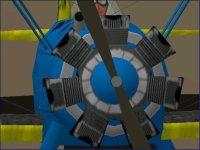
Engine build details: The 7-cyl engine block is one component made up of 36 parts with a slanted front on the cylinders, and has a rounded structure infront as a kind of cone, onto which the propeller and prop-axel are placed. Behind the engine block is the exhaust ring structure.

Thanks for your offer of looking into the matter!

Cheers,
Aleatorylamp
 

Attachments

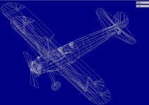
  • Blueprint-3D.jpg
    Blueprint-3D.jpg
    91.5 KB · Views: 0
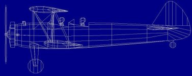
  • Blueprint-side.jpg
    Blueprint-side.jpg
    38.5 KB · Views: 0
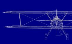
  • Blueprint-front.jpg
    Blueprint-front.jpg
    48.2 KB · Views: 0
Last edited:
Hello Aleatorylamp,

I will try to check out the engine arrangement when I get a chance. Hopefully the Development Machine is cooperative.
I had been thinking of how to go about doing a 9 cylinder engine because it would be the more resource intensive and could not get it below two Components for the engine block and cylinders and one Structure for the front of the crankcase.
The issue with the 9 cylinder engine is that there are at least 9 copies of everything.
Yet one more Component would be needed for the set of pushrods up front as well.

What I was really wondering about was why you didn't just add the cylinder heads to the same Component as the cylinders but I suppose I will find out when I go looking at the source.

- Ivan.
 
Good morning, Ivan,
I described this on the thread a while back, and yesterday forgot
to mention the 7 separate cylinder-heads. They are insignia, outward
facing parts and their job is to cover up some of the cylinder-wall bleeds.

If more components were to be needed for the engine, the fuselage cockpit
section is made up of several individual components, criteria being what is
glued on the top.

Thus, in order to cover up belly-bleeds, a head - torso - cockpitcover sequence
or a windowframe - windowscreen sequence has its own fuselage slice component
glued underneath, plus perhaps an extra adjacent fuselage-floor panel to cover up
bleeds facing forward or backward in a slant.

There is probably a better way of doing the cockpit area in one component, and
possibly glueing the crew and windscreens, cabinbacks and cabincovers in a single,
long, complicated sequence, that I, however, am unable to provide.

Anyway, I feel that the engine bleeds are not too bad though. The exercise of trying
to remedy them may be too hard and taxing, but if you are willing to give it a try, this
would of course be very welcome!

I´m still not too sure if I am interested in making a more powerful, perhaps 360 or 450 Hp
powered air-show Super-Stearman. It would need a 9-cylinder engine, simply having 2 more
cylinders in its star-shaped component, with similar bleed results to the present 7-cyl engine.

So, I´d be quite happy to leave it as it is now!

Update: Slight change in plans:
As I have a 9-cyl Lycoming engine which is practically done but just needs a little slanting back
on the front of the cylinders,
I´ll have a look at how this will display, and take it from there.

Cheers,

Aleatorylamp
 
Last edited:
Hello Aleatorylamp,

I had already seen in earlier posts that you put the cylinder heads as Insignia Parts to cover up some bleeds.
I just wasn't sure why that was necessary.

I do have a couple other questions though:

Why do you slant the cylinders backwards?
I don't believe the actual engine has that form.

Why didn't you flare the cylinders as they went out?
It would have been pretty simple to do and added to the appearance.

Why do the rear cylinder faces only go part way down to the crankcase?
If it makes no difference in appearance, you should run the rear cylinder faces all the way down to the crankcase because then there would not be any minor mismatches of lines AND it would actually make the model less complex because there would be fewer vertices needed to draw the Component.
That statement may sound counter intuitive but if you read through the SCASM code that is generated, you will see what I mean.

I debating on cleaning up the engine bleeds in your design or rebuilding the entire engine to a design I was thinking about.
I believe that either one can be done with fairly minimal bleeds though not completely bleed free.
The problem is that if I do a major redesign, it probably will not match your existing textures.

- Ivan.
 
Hello Ivan,
Thanks for your comments.
I´ll go through them in order!

- As I had been discussing with Smilo on the thread, the overall engine shape seemed better slanting
the front of the cylinders backward. This would be even more fitting in the case of the Lycoming
engine (which I didn´t use...), which has the exhaust stack in front.
I had also made trials with aft forward slants, generally including the rear exhausts in the shape of the Continental engine, but it looked awkward. Trials with forward AND backward slants together looked worse.
Perhaps the only other possibility was to keep them without slants as they were before, but we thought it looked better with the backward slant.

- Outward flaring cylinders were absolutely prohibitive because this increased bleeds to an unacceptable level.

- The cylinder backs only partially go down up to the exhaust ring behind. It prevents bleeds, because engine AND exhaust ring are grouped in Nose (vertice number increase caused no complications because the low parts count). There were too many elements in the front of Body Main to include the exhaust ring and its exhaust pipe, due to the air intake elements behind it, which are in Body Main.

Regarding my new trials with a possible 9-cylinder engine:
As happened before on my first 9-cyl engine some years ago, 9 cylinders cause worse bleeds than the 7.
This was to be expected, and I found it better (of course), if left untextured. Pushrod and exhaust details infront, compensate for this to a certain degree, so If I were to supply a Stearman with a 9-cylinder engine of my own making, this is how I would do it.

On one hand, should you decide to build a new 9-cylinder (or 7) engine, improving it with SCASM, it would of course be very interesting! Thanks for the offer.

I know that the existing texture would be no good and I would have to re-do it, even if such an endeavour for 9 cylinders is quite nightmarish.

However, on the other hand, I tend to feel that it will be too complicated, and it is questionable if all the effort will be worthwhile.

Cheers,
Aleatorylamp
 
Revised Stearman Nose Group

Hello Aleatorylamp,

I loaded your AFX last night and made a few revisions.
My Development machine was behaving rather well relative to how it has been recently.
There were only about a dozen failures over the couple hours I was using it.
The majority were AF99 crashes and the rest were CFS crashes.
One AF99 crash was particularly interesting because the task bar entry did not go away but I could not terminate it or do much else.
Even a proper shutdown was not possible and I had to use the reset button.

Description of Modification:
Your Engine looks the same but the motor.afc Component has been recreated with new Parts using your originals as templates.
This was done because I was getting confused with your naming convention with just sequential numbers.
The new motor.afc Component should have fairly minimal bleeds even with the included cylinder heads and actually takes out a couple other bleeds of the cylinder walls.

The exhaust pipe bleed has been removed but to do this properly, I had to redo the entire assembly sequence of the Nose Group.
I also needed to create 3-4 new Glue Parts to assemble in the new sequence.


I still don't quite understand why the cylinders are slanted backwards, but I guess I will need to look more closely at photographs of the Continental R-670 and see if it makes more sense.
I believe that with the current motor Component, outward flaring cylinders should not cause any prohibitive bleeds at all.

The number of pieces in the Nose Group should not cause problems if you can find a good Glue sequence.
I didn't quite finish gluing everything; I just added enough Glue to cure the obvious bleeds.
The number of Parts is not really the "complexity" I was describing earlier.
Sometimes a project can be well under the resource limits but refuse to build properly.
I believe that is because there are some internal array limits in AF99 that are not well documented and when they are exceeded, the project starts to have errors.

I do not believe that SCASM is required to have a really good looking exposed cylinder engine. I believe a pretty good one can be done with at least two Components and a boatload of Parts and Glue.

I could also see from this AFX that our responses to running out of resources is quite different.

I had not been following this thread in detail up until a few days ago when I finished the BV 141B.
I take it that the texturing process for the engine was a painful process?
I also don't like working on the engine textures for my models with radial engines.

Take a look at the changes attached and see if they make sense to you.
If not, I will try to explain further.

- Ivan.
 

Attachments

  • Stearman Modified.zip
    214.2 KB · Views: 0
Hello Ivan,
I´m glad that your development machine was working better than usual.
The work you have done on the engine is definitely very commendable!

I´m sorry about my strange numbering system and the complications it
caused, but I wasn´t counting on anyone´s intervention when I built the
engine. It does have its own logic, admittedly a rather obscure one,
and quite futile to explain!

I´ve observed how the ordering sequence of parts within the radial engine
component plays a crucial role in drastically reducing cylinder bleeds, and
eliminates the need for the insignia labelled cylinder-head parts I had to
put in separately.

Also interesting are the changes in the Nose Group glue sequence, which is
basically reversed. Needless to say, the results are very good.

The 7-cylinder cooling vanes were quite difficult to line up on the texture
bitmap, and had to be done line by line by hand, but it wasn´t too bad.

Now, a 9-cylinder engine Texture will be more difficult, but possible.
Also, a 9-cyl radial using the new building system you showed for the
7-cyl engine will yield similar good results.

This that will facilitate, for example, a new upload of a 9-cyl Lycoming
engined Army PT-13A with Number 112 registration, with now correct
performance in the .air file as per specification.

Another thing it will facilitate, should I be that way inclined, is the
creation of an acrobatic Super Stearman with a colour scheme as yet to be
decided.

Then, the existing Army PT-13A upload would be updated with the new almost
bleed-free 7-cyl engine, correctly re-named PT-17, as it has a 7-cylinder
Continental engine.

Anyway... now we have the same cumbersome situation as what happened with
a couple of my previous models, where improvements cropped up after a first
upload and required updates, which I always find rather untidy.

I always try to avoid thes things by posting WIP attachments, but as my father
always said:

"Firstly, things happen differently, and secondly, from what one expecs!"

The simplest way would probably be to just make a new model directory
for each of the 2 Stearmans, send them to Rami, and ask him to slip them into
the 2 existing upload zips, and indicate the update in the presentation text.

>sigh< I´ll see what I do.
Cheers,
Aleatorylamp
 
Updates to Existing Upload

Hello Aleatorylamp,

For what it is worth, I actually downloaded your latest WIP5 ZIP file and loaded it and even went back to see what the discussion was about before I started commenting here.
There was not enough information in the thread or in the as-built model to come to any conclusion so although I could see a few problems, I had no idea why they were happening.

The technique I used on the 7 cylinder Continental rebuild was also used a few years ago when Hubbabubba and I were discussing building in AF99 versus building in SCASM and again when I was first trying to build an engine cowling for my B-26 Marauder project.
It is actually possible to build a single Component engine cowling with minimal bleeds even with the two air filters included.
The problem comes when attempting to texture the single Component which is why I did not pursue it further.
(But it WAS amusing to look at something that complicated as a single Component.)

I know that both of those discussions were very old because the images I posted for both discussions were lost in one of the visits by an attachment eating monster, but I still have them around on a flash drive somewhere.

Back to the Subject of this post:

If you need to update an upload, you actually do not need to bother Rami at all because you can do it yourself.
Note that on your own uploads, you have the ability to "Edit".
That ability even goes as far as to substitute a new ZIP file.
I know it works because I have done it a couple times.
Please note that my P-40N Warhawk is not version 010 which was the initial upload but was changed very shortly after it was uploaded and is now 011 which corrected the description in the AIR file. I had listed the Length specification as that of a Short Tail P-40 in version 010. The description of the download was also changed at the same time as you can see.

I also hate having to go back and fix things which is why I do so much testing before any release.
In your case, it wasn't so much an error as a different way of doing things so it would not have helped.
With the BV 141B, I actually put together the ZIP file three separate time because each time I found something that wasn't quite the way I wanted. At least two issues were simple spelling errors and I am still not convinced I got them all.
Fixing little stuff like that is not fun!

- Ivan.
 
Hello Ivan,
Well, granted - I hadn´t included any AFX in the WIP files because
I wasn´t expecting any interest for it. Next time, just in case, I´ll do so.

OK, I´ll try editing my own upload as you say.
I´d thought it was only possible with the text files.

As far as I can see, in an un-SCASMed semi-complex textured component such
as a radial engine, the expextedly least visible parts are listed first. I have watched
the sequence in the Component editor.

Applying this system, a 9-cylinder engine without the tween-cylinder crank-case
parts, which would just be ommitted, would have its parts following the same ordrely
pattern, but including 9 instead of 7 cylinders.

I´ve built the engine, so all I have to do is rename the parts in a similar fashion to the
7-cyl one you so skillfully "re-built".

As it is a Lycoming engine, the front slants will be left in as they "include" in their volume,
the shapes of the exhaust pipes leading into the collector just behind the propeller.
The valves, can actually just be one 2D light grey spider-shaped part where rods slant
backwards, and this is glued to another 2D part, an orange ring shape, also just behind the
propeller, but infront of the rods. This should do the trick.
The texture will be difficult, but I´ll manage.
When done, I´ll post a screenshot.

Anyway, if all goes well, I can
a) correct the existing uploads, including the re-naming of the Army PT-13A to
PT-17, and then
b) for the 9-cylinder engine, add a new upload with a PT-13D Army unit Nr. 112
with a 225 Hp Lycoming R-680-17 engine. (125 mph Vmax).

...But I can also be wicked::a1089:

I could turn the new 9-cyl upload into a PT-13B with the controversial but historically
documented and hushed-up 280 Hp Lycoming R-680-11 engine with a wooden propeller,
giving following plausible test results :
100% power: 281 Hp, 135.2 mph, Vmax, 16-deg wooden prop, 2260 RPM.

Other additional options for fancy-coloured aerobatic hot-rods, should anyone
be interested, could be:

Lycoming, with plausible test results:
100% power: 360 Hp, 154.1 mph Vmax. CV Prop, 2300 RPM.

P&W R-985 Wasp Junior, with plausible test results:
100% T.O. power: 450 Hp, 164.4 mph Vmax. CV Prop, 2300 RPM. (Max. Cont. 400 Hp at 2200 RPM).

But the problem is that Udo can´t do the textures, as he´s busy until well into the new year.

Well, we´ll see what we can do.
Cheers,
Aleatorylamp
 
Windscreen frame colour change?

Hello folks,

I hope the Halloween party last night was nice!

There´s a small question on the windscreen-frame colour:
Photos show them in metallic grey and also in the colour of the
plane, so it would be in AF99 medium yellow or medium blue.

After Udo textured the plane he asked me for yellow and blue
frames, for the FS98 upload at Flighstim.com he´s undertaking.

Personally, it makes no difference to me as I like both, but as we
are updating the machines, I could change the windscreen frame
colour, if desired.

Any opinions? If you say "as you wish", I´d leave them in light grey,
but as this is more of a joint effort and I´m always bouncing ideas off
others, I like to take everyone´s opinion into account.

I´ll also adjust the idle speed so that the engine won´t stop if you
don´t accellerate a bit, even if I prefer it that way... like a badly
regulated old car, ha ha!

OK then! Cheers,
Aleatorylamp
 
in the early morning fog
of just waking up,
i'm with Udo,
regarding the windscreen.

at first, the engine stalling
after startup was annoying.
but, in time, i grew to like it.
it keeps me more involved
in the startup process.
i say, keep it.
don't for get to make a note in the readme.
as if anyone really reads them.
 
Now, flared cylinders, but how strongly?

Hello Smilo, Hello Ivan,
Thanks for the prompt response!
Very good - I´ll take your suggestions into account.

Funny, the thing with the idle-speed, that it should be
appealing instead of annoying!

I was just waiting for the confirmation on the windscreen
colour mod in order to SCASM for the Virtual Cockpit.

Anyway, Ivan´s engine improvement is definitely a big plus point!
Apart from eliminating cylinder bleeds, the new parts configuration,
that
now doesn´t need the insignia cylinderhead panels, now allows
the engine texture to
display the cylinder heads much more correctly.

Before proceeding any further, though, I´ll re-try the outward flaring
cylinders that
didn´t work before. There seems to be a strong possibility
that it will work now.
Let´s see...

Update a while later
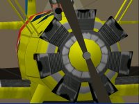
:... It worked! Now I´ll adjust the textures, but before:
There are two flaring "strengths". The blue plane is less flared, the yellow one,
more. Which looks better? Would the stronger flaring be overdoing it a bit?
Here´s are 2 screenshots.


Then, once I´ve rectified the texts I´ll replace the existing uploads
with
the revised versions.

The next step after that will be to clean up my 9-cylinder Lycoming
engine with Ivan´s improvement system, and prepare a new Army
Corps version Nr. 112 with it, and a possible acrobatic hotrod.

Because Lycoming R-680-17 performance with 225 Hp is virtually identical
to the existing 220 Hp Continental powered Stearmans, I do think it will be
justified to go for the 9-cyl, 280 Hp Lycoming R-680-11 for the new upload,
as it IS historically documented, and will make the new release a little more
attractive, with its 11 mph speed increase.

It will also serve as a convenient in-between comparison to a possible later
release of an acrobatic model - the 164 mph hotrod!!

If you have any preferences as to the colour scheme of an un-cowled hotrod,
do let me know.

Cheers,
Aleatorylamp
 

Attachments

  • Flared_cyls.jpg
    Flared_cyls.jpg
    46.1 KB · Views: 0
  • Flared+_cyls.jpg
    Flared+_cyls.jpg
    54.2 KB · Views: 0
Last edited:
To flare, or not to flare, that is the question.

Hello Gentlemen,
I rather missed the more obvious question...
Does the shape of the cylinders flaring outwards really look that good?

I´m not too sure, and perhaps on the model, the previous shape looked
more harmonic. I don´t know... Wouldn´t the cylinder-head edges look
a bit too sharp now?


What´s your feeling about this? I´ll keep either the softer or stronger
flaring type in, should you like it more than the un-flared version.
(as shown in Posts #44 and #46 show).


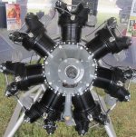
Here´s a photo of the original for comparison purposes.

Cheers,
Aleatorylamp
 

Attachments

  • ContinentalW-670.jpg
    ContinentalW-670.jpg
    102.4 KB · Views: 1
using the photograph as reference,
i held a protractor to the crankcase
at the top cylinder base.
the line to the outside edge
of the left valve cover
is roughly 80 degrees.
therefore, i would be more inclined
to vote for the more flared example
on the navy version.

just my opinion, of course.
 
Hello Smilo,
Wonderful! Thanks for your prompt and ever
useful assistance and opinion.
Will do! :encouragement:
Cheers,
Aleatorylamp
 
Flared and blurred!

Hello Folks,
The easiest was actually shaping the flared cylinders, and the nice
part was seeing how the cylinder walls did not bleed through at all.

Then, fitting the cooling vanes in the texture was the hard part,
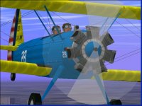
but it went well. I even managed to blur the bitmap a bit - Udo calls
it "soft-washing", and here´s a screenshot.

Cheers,
Aleatorylamp
 

Attachments

  • Flared!.jpg
    Flared!.jpg
    63.8 KB · Views: 1
Back
Top