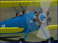
B-S Model 75 - the visual model

Hello Aleatorylamp,

Aleatorylamp said:
The easiest was actually shaping the flared cylinders, and the nice
part was seeing how the cylinder walls did not bleed through at all.

;-)
Sometimes it isn't a matter of things being impossible.
It is just a matter of not knowing how to do them YET.

I have something similar working on AIR files, so maybe one of my very old projects may be revisited soon. That one has only taken me a few years to finally see a solution.

Your cylinder textures look good. The way you did things gives me an idea for my next project and a way to improve other textures I have used for radial engines.

- Ivan.
 
Hello Ivan,
"Sometimes it isn't a matter of things being impossible.
It is just a matter of not knowing how to do them YET."

...Because the AF99 manual is meagre and its explanations frugal.

The assembly sequence within the engine component appears to be crucial for complex components. I remember you saying so before, but from there to understand how a logical placement would run, is another matter. Thus, concave areas between cylinders don´t disappear because parts order is listed inversly to the visibility priority.
Update: I´ve just finished the 9-cylinder engine component and it worked out very well too! :encouragement:

Thanks for your good words on the engine texture.
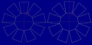
The thing is, the square shaped area in where the engine sits on the model is covered by a rectangular 256x128 bitmap, so cylinders must not only be rotated by a given angle starting with number 1, but also stretched sideways depending on their position.

A lengthy trial and error, l/r cylinder pair by pair process, to get the cooling vane lines right.
...AND pixels can form quite irregular zig-zags when lines are not orthogal.
This time it was for 7 cylinders, and now we start all over again for 9-cylinders...
:eagerness:

I think I´ll start by making a 9-line kind of spider or star, and try to get the centre lines lining up with the cylinders on the model, and then place lines at right angles for the cylinder-head gasket, to get my bearings before fillinf in the rest of the lines for the cooling vanes.

Can you believe that with all the engine tuning confusion, I got the correct Continental engine performance with the wrong engine?!!: I ended up using the Lycoming 9x75.55 cu.in. with 5.5:1 compression ratio instead of the Continental 7x95.44 cu. in. with 5.4:1. But it´s OK now.

It required an ever so slight Torque adjustment, and the revised and improved version has the correct cylinder/piston parameters. Performance is identical except for idle power, which no longer conks out!! I´ll have to reduce the idle setting a bit so that the engine will stop if you don´t give some gas quite soon...

Well, I think I can start preparing the 2 revised versions now, to replace the uploads.

Cheers,
Aleatorylamp
 
Last edited:
Hello Aleatorylamp,

This is another one of those situations in which a LOT could be explained visually over a long lunch meeting but it is hard to do this via words in a forum post. Let's try anyway....

Aleatorylamp said:
The assembly sequence within the engine component appears to be crucial for complex components. I remember you saying so before, but from there to understand how a logical placement would run, is another matter. Thus, concave areas between cylinders don´t disappear because parts order is listed inversly to the visibility priority.

You are about half correct in your paragraph:
Component assembly order is crucial - True.
Concave areas don't disappear - Whether concave areas disappear has nothing to do with assembly order.

Explanation:
Aircraft Factory 99 is either too stupid or too smart for its own good.
A COMPONENT has a "Central Point" or "Center of Gravity" which is calculated from the polygons or vertices from which it is comprised. I have my theories as to how this Central Point (CP) is calculated but won't get into details here because my ideas are not so rigorous yet.
Each polygon of the Component can have a ray drawn from the CP to its center which then determines the facing of the polygon: All polygons face Outward.

If Smilo is reading along, he is probably thinking AD 2000 does it in a much smarter way by the order of the vertices and he is right. That IS the smarter way, but it leaves the task up to the aircraft designer.

Thus assuming that the CP is in the exact center of your motor Component, a cylinder wall will continue to display until its inclination becomes so steep that it crosses the center axis. I was pretty sure you were not going to do that which is why I told you that putting a flare / taper into the cylinder would not cause any additional bleeds.

The ORDERING SEQUENCE within the Component is what determines bleeds. All I really did to your motor Component was to adjust the order of Parts. I renamed everything because I didn't want to do math to figure out which piece I needed to find next in the sequence.

You have a couple of my AFXs, so look closely at how I name and number the Parts. It is boring but makes it really easy to locate where something is supposed to be. Sometimes the numbering looks odd but usually that is because the Parts are numbered in the order that they need to be added. This saves time when there is a need to rebuild a Component inside AF99.
My early projects were not so well organised and were a lot more confusing to follow.

As I commented earlier, none of the Parts would disappear regardless of the ordering.
The ordering is done so that the Parts which are highest visual priority (never covered by anything else) are listed last, followed by the ones of lesser priority and so on.
That is the "big secret" not that I ever intended it to be a secret.

In fact, there are still bleeds in the motor Component. Some of the cylinder walls are bleeding through others but that is impossible to avoid. I just ordered things so that the bleeds are hidden as much as possible.

Aleatorylamp said:
The thing is, the square shaped area in where the engine sits on the model is covered by a rectangular 256x128 bitmap, so cylinders must not only be rotated by a given angle starting with number 1, but also stretched sideways depending on their position.


Why are you using a 265 x 128 texture when it would look the same with a 128 x 128 texture and be much easier to draw?


Aleatorylamp said:
Can you believe that with all the engine tuning confusion, I got the correct Continental engine performance with the wrong engine?!!: I ended up using the Lycoming 9x75.55 cu.in. with 5.5:1 compression ratio instead of the Continental 7x95.44 cu. in. with 5.4:1.


Sounds like pretty good proof that these two engines were not that far apart in performance and that if something works for one of them, it works for the other.
There are obviously other design characteristics that make it possible to hotrod the Lycoming but not the Continental engines.

- Ivan.
 
Hello Ivan,
OK, Understood! I´ve just increased the taper on the 9-cyl engine a bit more to fit the photos a bit better, and it continues to display fine - obviously, when one takes into account your explanation for this fact!

The texture fitting is going slow but OK too.

I always use the full width bitmap, as fitting the 1/2 width of the bitmap is too confusing for me to figure out.

Regarding the 2 Lycoming and Continental engine types, both seem to be quoted at 220 Hp or at 225 Hp, seemingly depending on the suffix number. That was part of the confusion, but not the serious one.
Both can be set for 220 Hp at 2075 RPM (well... 2080), and 225 Hp at 2100 RPM.

They really do have virtually identical performance, also in the Sim.

It took me a while to figure out though, once I had discarded the 105% power and its misleading information as to RPM increase, which was about twice too high.

The difference in number of cylinders, cylinder displacement and compression ratio cancel each other out.
Their performance curves even show how they were pushed up to 240 Hp at higher RPM, with a higher compression rate (6:1). I believe these also had better cams.

Then the Lycoming, of course, could further be made even more powerful by adding a supercharger and possibly 7:1 compression ratio. This way they got up to 360 Hp out of it. Interesting technology!

Cheers,
Aleatorylamp
 
Hello Folks,
Here are the links to the revised versions of the two Stearman 75 models.
I have just now edited the upload to replace the files. Thanks for telling me how to do it, Ivan!

http://www.sim-outhouse.com/sohforum...id=19&id=23105
http://www.sim-outhouse.com/sohforum...id=19&id=23107

Improvements include:
1) New almost bleed-free radial engine component with more realistic, and imposing
looking, outward flaring cylinders. This has been possible thanks to help from Ivan!
2) Windscreen frames are now in the colour of the aircraft. Blue for the army version
and yellow for the Navy one.
3) Idle speed adjustment now won´t let the engine die out while idling.

Thanks for your support.
Enjoy!
Cheers,
Aleatorylamp
 
Hello Smilo,
Good! Hope you like them.
I´m working on the Lycoming engine textures now. It´s never-ending...
The art program likes the 9-cylinder vane-angles even less than the 7-cyl ones.

Hello Ivan,
Correcting my comment on the higher output radials I mentioned, the
360 Hp lycoming isn´t supercharged, but had 7:1 compression, this
seems to work fine in the sim with a CV propeller.
The supercharged engine is the P&W Wasp Junior, which also sims fine.

Well, cheers then!:teapot: Time for my morning tea.
Aleatorylamp
 
Hello Smilo,
I hope you are managing to defend yourself bravely against the
ruthless onslaught of the winter. No small task.
Here we have become soft and spoilt by the hot summer, although
it did start drizzling today.
Anyway, now to the more interesting (perhaps?) stuff:

Hello Folks,
To make the next upload a bit more interesting with the 9-cylinder
Lycoming engine, I have opted for the 280 Hp R-680-11 engined
PT-13B in metallic grey colour scheme.

There is enough historical documentation to justify such a release,
as the 255 Stearman PT-13B´s delivered to the Army Air Corps with
this engine are mentioned by:


1) Aerofiles.com:
-----------------
PT-13B 1940 = 280hp R-680-11.
POP: 255 [40-1562/1741, 41-787/861].
(These S/N´s are also: 75-0847/75-0921 and 75-0119/75-0298)
PT-13C 1941 = PT-13A repowered with 280hp R-680-11.
POP: 6 modifications.

2) Book titled
--------------
"American Military Training Aircraft:
Fixed and Rotary-Wing Trainers Since 1916".
A succession of new production orders over the next four years
accounted for the delivery of... ... and 255 PT-13Bs (280 Hp R-680-11 engines)
in 1940... In 1941, after being re-powered with
R-680-11 engines, six PT-13As
were re-designated PT-13C.


3) All Aero writes: (slightly different numbers)
-------------------
...Then came 220 PT-13Bs with the 209-kW (280-hp) Lycoming
R-680-11s of which six became blind-flying PT-l3Cs...

4) Comment on Airliners net.
----------------------------
...the R-680 was used in the PT-13 variant of the venerable
Stearman, albeit at a 220 HP rating (the R-680-7) or 280 HP
(R-680-11).

5) Photo of of a metallic grey coloured 1941 Boeing-Stearman
-----------------------------------------------------------

PT-17 “Kaydet” (N55721, AF 41-806, s/n 75-866, Model A75) on
display (6/19/1999) at the 1999 Camarillo Airshow.

This Serial Number corresponds to a PT-13B model as mentioned
above, seemingly re-designated as PT-17 after Normalization, and
possibly re-engined with to meet FAA regulations of keeping wooden
Propellers for 220-225 Hp powered engines.

The USAF emblems on this colour scheme are more modern than what
corresponded to the Army Air Corps in 1940, so the aircraft in the
photo must have been re-painted later.

In 1940, emblems on the metallic grey livery were white stars with
no red circles inside) on blue roundels, without lateral blue/white
squares, and with U.S. ARMY written underneath on the lower wings.

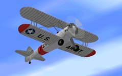
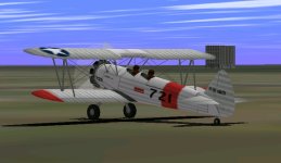
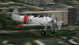
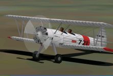
So, here is a screenshot of a most plausible version of the PT-13B.
And a WIP attachment for it.

Note: Engine textures are unfinished, but the plane flies appreciably
differently with the 60 extra horsepower!
Incidentally, everything else is identical in the .air file, including propeller tables.

I´ll try to get the textures a bit better - they look a bit too white,
maybe, although
took a light grey.

Also, there is something wrong with the propeller animation - the blur is too big.
Strange, because I used the same one as on the others - should be easy to fix though.

Cheers,
Aleatorylamp
 

Attachments

  • PT-13B-a.jpg
    PT-13B-a.jpg
    42.7 KB · Views: 0
  • PT-13B-b.jpg
    PT-13B-b.jpg
    44.4 KB · Views: 0
  • PT-13B-c.jpg
    PT-13B-c.jpg
    51.5 KB · Views: 0
Slightly better radial engine

Hello All!
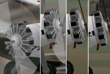
Because of the increased number of cylinders on the 9-cylinder engine, to fit them in better, I had eliminated the small crank-case parts between the cylinders at the base. That way each cylinder touched the adjacent ones, as shown on the right picture in the screenshot.

Visually it seemed over-simplified and possibly didn´t display as good, so I put these small parts back in.
As per Ivan´s instructions, these are lowest-priority parts and go into the Component Listing first.

Not only does it display better in the between-cylinder area, but it also makes the cylinders more flared, so they look more realistic.

Now I´m still working on the engine texture... It still isn´t done, it´s lop-sided in some parts, as to be seen on the screenshot, but the shape does look better than before!
BTW, valve pushrods and frontal exhaust ring aren´t on yet, as these would obstruct the view of the texture I´m working on.

Also attached, just in case, are some new source files, should anyone wish to have a look-see inside!

Update: The "new" source files were from last night - not the newest from this morning. I goofed there!
Here are the "newer" ones, correctly now, the screenshot as well...
The three top cylinders are already quite good.

Cheers,

Aleatorylamp
 

Attachments

  • Radial9-new.jpg
    Radial9-new.jpg
    41.8 KB · Views: 1
Last edited:
Hello Folks,
Further research reveals that the exhaust collector ring is not on the front part of the engine for the more powerful versions of the Lycoming R-680 radials.

I understand that on the 220 Hp engines this had a warming effect, preventing the engine from cooling too fast on approach or cruising, but did not cause overheating problems under full throttle. However, more powerful versions needed more heat dissipation, which a frontal exhaust ring would have interfered with, so they had to keep it behind. It´s just as well for me because it´s easier to build that way!

Then, the exhaust pipe was underneath - see the screenshot! - the valve pushrods are on as well now.


... of course, I still have to finish the cylinder textures... Hmmmmm, procrastinating again...
Cheers,
Aleatorylamp
 
Hello Folks,
I´ve managed to get engine textures to about 80% finished, and it´s looking better.
The cooling vanes are starting to be as I want them to be, and the engine is slowly
getting the look. The shape of the pushrods part is better adjusted, as is the front
round bit on the crank case.
Slowly but surely, without hurry or pause...
Cheers,
Aleatorylamp
P.S. I keep having to delete older pictures as they become obsolete because of my
always almost full attachment cuota. Sorry about that, but it´s inevitable.
 

Attachments

  • getting the look.jpg
    getting the look.jpg
    57.8 KB · Views: 1
Last edited:
Tailwheel bleed gone, and 3D Pushrods now...

Hello All!
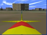
Upto now I was getting a persistent tailwheel bleed through the rear fuselage aft
of the cockpit, viewed from the virtual cockpit position, which no amount of glue
or sequencing could take away.

But of course, as often happens, it was a matter of concept and paying attention:

The tailwheel bled through the rear-fuselage component aft of the cockpits.
This component was grouped in Body Main. However, the wheel is glued to the
tail-fuselage grouped in Tail.

So, obviously it bled through! Captain Obvious strikes again!!

The only way out was to group the rear fuselage, into Tail as well.
Strangely enough there are no bleeds elsewhere, and the tail empenage
displays better from the virtual cockpit viewas well. Another small improvement...

Possibly it will warrant a further upgrade of the existing military stearmans,
for the sake of correctness.


Update:
I´m finishing the cooling vanes better on the engine texture, but also managed
something
that I didn´t think would work:

3D pushrods do indeed display properly, and t component has 37 parts, as opposed
to the previous single 2d part for all the pushrods.

Cylinders also no longer slant forwards - that had been to include the pushrods into

the engine shape, which is no longer necessary as they are now a separate component.

Here´s a compound screenshot - I think the engine gains a lot!

P.S. I ´ll try and divide the prop-axel in two to fix the propblur bleed on the axel.
A very minor thing, but
with parts count at only 121.1%, there´s room left for little things.

Cheers,
Aleatorylamp
paperclip.png
Attached Images
 

Attachments

  • Rods-3D.jpg
    Rods-3D.jpg
    72.5 KB · Views: 1
Last edited:
WOW!!!
she's progressing rather nicely.
well done...and i'm pleased to see
you're learning new techniques.
i guess, after all these years,
the stearman is still a trainer
on so many different levels.
 
Hello Smilo,
I´m glad you think so! I´m slowly getting there...
I never thought it would work out that well!

...But then Ivan HAD pointed out the possibility of putting the

pushrods into a component, and there was one last one free for that!
It looks like one never ceases to learn new tricks - the training never stops!

The prop axel is also better now, divided in two, and with the last touches to the
cooling vanes on the lower cylinders tonight, with a bit of luck, I can soft-wash the
engine texture tomorrow, correct the virtual cockpit view with SCASM, and upload
this half-hotrod at the weekend.

With so many hours, or rather days, spent on the 9-cylinder engine, to make it profitable, I´ll
paint up a REAL hotrod for it - the 400-450 Hp one, which had the 9-cylinder P&W R-985.

Some fancy colour scheme would be in order for that one. Something with sun-rays
on the wings and fire on the fuselage, perhaps. Any suggestions?


Cheers,
Aleatorylamp
 
never was much of a "look at me", flashy, hot rod fan.
i preferred the subtle, nondescript, sleepers.
you know the type, a nearly invisible dud shows up,
then, blows the doors off of the competition.
but, that's american street cars.

the brightly colored trainers were just the opposite.
for the most part, they're screaming,
"KEEP CLEAR!!! I DON'T KNOW WHAT I'M DOING"
 
Hello Smilo,
I see your point! The bragging inferred by flashy stuff could also at best conceal
insecurity,
if not incompetence.

Moreover, this being actually for a Combat Flight Sim, aerobatic hotrods would really be
somewhat out of place, I suppose, so I´d just as gladly leave it at the three military
versions we have upto now.

In a few minutes, I´ll start uploading the new silver/grey/white and red PT-13B model.
After that, and taking advantage of the improvements I´ve been able to come up with
for the PT-13B, I´ll also upload the 2nd. revision of the two previous Stearmans - the
blue/yellow Army Corps unit and the yellow U.S. Navy one.

It has been quite a lot of work, and very satisfying at that, I must say, so I think I´ll
call it a day and move on to the planned Electra Model 10.

Unless of course I have misunderstood your point, and what you are saying is that a
discrete paint
scheme would be best for a 450 Hp hotrod Stearman, if we were to want
one. Maybe one in dark
green or dark blue, with grey wings....

So, do we want one?

Cheers,

Aleatorylamp
 
U.S. Navy and Army Corps Stearman Updates, 2nd Revision

Hello All!
I´ve just replaced the upload files corresponding to the yellow
U.S. Navy Stearman-75, and the blue/yellow Army Air Corps
Stearman-75, incorporating the improvements I managed on

the latest model: The crankcase texture is centered and the
rearwards virtual cockpit view no longer shows the tail-wheel
through
the aft fuselage.

http://www.sim-outhouse.com/sohforum...id=19&id=23107
http://www.sim-outhouse.com/sohforum...id=19&id=23105

Enjoy! Thank you for your support.
Cheers,
Aleatorylamp
 

Attachments

  • Navy Stearman V2.jpg
    Navy Stearman V2.jpg
    37.9 KB · Views: 0
  • Army Stearman V2.jpg
    Army Stearman V2.jpg
    52.8 KB · Views: 0
waaay back in early august, i cited
an article in Aviation History magazine,
which helped get the stearman ball rolling.

this month in the letters to the editor,
a gentleman talked about his 1944,
primary flight training in a stearman pt-17,
"the plane with the built in ground loop"
and that he soloed in about six hours of instruction.
a few pages later, there is an article
about the reopening of the Lone Star Flight Museum.
what do you suppose is the closest aircraft in the photo?
yup...a stearman with yellow wings and black fuselage.

to answer your question, Stephan,
i'm ambivalent on the subject.
if you want to add a hot rod,
add a hot rod. if not, don't.
as always, it's up to you.
my apologies for not being more definitive.

as things are, congratulations completing a fine project
 
A nice trio!

Hello Smilo,
Well, I haven´t really found a nice colour scheme for an acrobatic version.
Many of the uncowled ones seem to be original Army Air Corps or Navy units
with their military colour schemes, either re-engined with more powerful
engines, or not... The flashy ones are all cowled, so I think I´ll leave it be.

The uploaded military trio collection is quite complete. Thank you for your kind
words. This kind of moral support is always important!

Hello Ivan,
Thank you for your help with the radial engine! I´m glad I was able to make the
9-cylinder one with the pushrod component the way you suggested.
The result was indeed quite striking.

Cheers,
Aleatorylamp
 
Back
Top