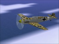
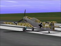
Conspicuous by Their Absence

Hello Smilo,

There is no need to move any posts. Although I may use the same images, the post itself would be different.I

believe this is a subject that requires some significant planning first.
I was thinking last night about what subjects to cover and came to the conclusion that no one single model really hits all the topics that should be addressed. Some of it crosses over to the 3D design part because a piece may need to be shaped a certain way to let it be textured.
A perfect example is the B-26 Marauder Cowl as a single component. Although the model can be built that way, there is no way to apply a texture to it that would make sense.

I also looked over the RO Me109E Trop last night and realised that it goes against almost everything I would describe in a tutorial.
What exactly do you find objectionable about the texturing of the 109E? If it is really easy to correct, perhaps I will do it.

Keep in mind also that not one of these unpainted subjects needs just a coat of paint to be releasable. The Dauntless is closest because I have what I believe is a pretty good flight model for it.

Unfortunately, *I* can't hit a thing with it on a dive-bombing run even though all the numbers seem right.
Perhaps it is a controllability issue. Perhaps it is just a simple untrained pilot. Although I can make one of these flight sim aeroplanes do pretty much what I want (or mebbe it is just because my aeroplanes have gentle flight models), I may not know WHAT I should be trying to do.

- Ivan.
 
Bungho to all.....papingo here

I believe there is a [cheats] entry in cfs.cfg that is
[cheats]
bombtrainer=1(or something like that--I'll check)
another usefull entry under[cheats] is allowslew=1
I have used it to compare combat speeds of various
opponents quick combat mode ect.
BTW what does addons=000000000 mean exactly
in missions?
papingo
ps where can I buy a decaffeinated coffee table?
(attributed to a US comic called Emo)
 
Just One Loose Thread....

Sometimes you gotta wonder....

Some folks already know that at some point I plan on building a Me 109G or K.

The tail on this 109E had a lot of issues and the more I poked, the more I was finding that should be fixed.

I figured it would be a good exercise to see if my ideas on doing the tail on the 109G/K would work because the shapes are generally similar to that of the 109E but without the bracing struts. If I could work out a method to eliminate bleeds here, it would certainly work on the later aircraft.

With that in mind, I spent a fair amount of time basically rebuilding the entire tail from the cockpit back.


I saw a few shape problems in the Aft Fuselage that did not look hard to fix. There was a bulge between the wing and tail.
As I poked further, I found that the general shape wasn't quite right either. I could just narrow things down or with a little more effort, I could change the cross section one station closer to the tail and get a much better looking result.
With improve the fuselage cross sections, the diamond shaped cross section of the rudder didn't quite blend in.
That would not need a lot of effort to fix either
As I reworked that to blend in with the fuselage (Messerschmitt's blending of the fin, rudder and tail cone is quite well done), I found that the profile of the tail was a bit off.
I reworked the profile and then found that the chord of the rudder seemed a bit short.
Adding a couple inches to the rudder chord is actually quite easy and would definitely improve the shape.

I figured I would first check the length of the actual aircraft to see how much room I had to work with.
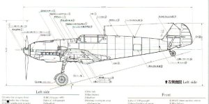
The overall length of model is 27.08 feet. A quick check of the Aero Details book shows that the length should be 8800 mm.
That works out to 28.87 feet..... which means this critter is 21.48 inches TOO SHORT!

In other words, there are a lot of things are are not quite in the right place on this aeroplane.....

Now what?

- Ivan.
 

Attachments

  • Me109E_Length.jpg
    Me109E_Length.jpg
    73 KB · Views: 0
"now what?" indeed.
options abound, right?

easiest option would be to drop it like a hot potato
and run away as fast as possible.

then, there's the rework the RO 109e afx, option.
there's no doubt, that the more you poke,
the more discrepancies you will find.
that could be a huge can o worms.

or, start from scratch and build a 109e to your standards.
then, like your P-40 project,
continue on with the f, g and finish with your k variant.
i guess, if you wanted to really go crazy,
you could start with a 109a used in the Spanish Civil War.

other than that, i don't know what to tell you.
as always, the choice is yours.
 
Hi Smilo,

Seems like you enumerated the options pretty well.

I have already chosen not to drop the hot potato. Whether or not it eventually comes out as something worth releasing is another story.
At this point, there is more stuff in this model that I have built or modified than what was original.
I believe the Tail Section is pretty much free of bleeds which took some serious doing.

The canopy frame has had some serious modifications though the general shape and dimensions have not changed very much.
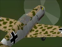
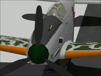
It is now textured with minimal bleeds. Note also the single frame at the top rear that replaces the earlier construction.

The spinner and extreme nose section are significantly modified. The spinner is actually 0.20 feet lower and significantly longer and wider.
The spinner is now textured and the the opening is unaffected by the texturing.

The entire fuselage behind the cockpit is rebuild with the exception of Stabilisers, the forward part of the fin. The two tailplane struts are the same dimensions but moved about 0.90 feet aft and are now separate top and bottom facing polygons.

The rudder has also been significantly reshaped in both profile and cross section.

I checked all the longitudinal locations and adjusted many of them but didn't check the vertical dimensions.

That is the current status.

I have thought about redoing the wings and landing gear, but at that point, there would be nearly nothing left of the original model.
It is a pull between fixing things I don't like and putting a lot more work into something that really isn't mine.

Regarding building the Me 109A and the rest of the line:
Although the designation remained the same, I am not convinced the 109E and earlier have much relationship to the 109F and later.
I have never been all that interested in the 109E though the amount of time spent on this model may mean that I end up doing my own version at some point because I have worked out most of the construction and assembly details even if the dimensions are not entirely correct.
Some of the techniques are transferable to the later 109 which is why I still experiment a bit.

Check your email....
- Ivan.
 

Attachments

  • Me109E_ModLFHigh.jpg
    Me109E_ModLFHigh.jpg
    56.2 KB · Views: 0
  • Me109E_ModTailClose.jpg
    Me109E_ModTailClose.jpg
    61.3 KB · Views: 0
  • Me109E_ModCanopyFrame.jpg
    Me109E_ModCanopyFrame.jpg
    53.4 KB · Views: 0
  • Me109E_ModSpinner.jpg
    Me109E_ModSpinner.jpg
    49.4 KB · Views: 0
  • Me109E_ModNewRudder.jpg
    Me109E_ModNewRudder.jpg
    29.5 KB · Views: 0
Just some Eye Candy

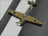
Here is a idea I had a while back. I would never have enough resources left over to do this on one of my own models, but this project has quite a lot of resources left over. Perhaps I need to learn these kinds of building methods because from an overall view, the model doesn't really look bad.
I don't like some of the construction methods but they do seem to work well enough.

I figured I would use up a few of those extra resources just because they were there. (You don't get extra credit for having resources left over.)

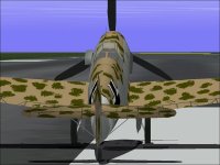
This is an interesting texturing exercise as well because although the inboard and outboard wheel patterns are both "round", they are vertically offset by 7 pixels to get the wheel centers aligned with each side. I may redraw the wheel faces if I get bored.

I also found when poking around that each wing is a bit over 5 inches too short.... The bleeds are not severe, but there ARE resources left over.

- Ivan.
 

Attachments

  • Me109E_WheelsFront.jpg
    Me109E_WheelsFront.jpg
    48 KB · Views: 0
  • Me109E_WheelsSide.jpg
    Me109E_WheelsSide.jpg
    54.6 KB · Views: 0
In the previous post, the wheels seemed a touch small to me.
Last night, I checked some documentation and found that my assumption that these were 600 mm wheels was incorrect.
They are actually 650 x 150 mm.

With the way I am building the wheels as components, the change in diameter was not terribly difficult nor was the change in width.
The change in texturing proved to be much more tedious because I took the opportunity to redo the hub textures.
There is also an odd (to me) texturing layout that I need to investigate further.

I also ended up relocating most of the texture mapping on the fuselage because I found that the part often extended up to the absolute edge of the texture file or even OVER the edge. There is plenty of overspray for the camo patterns and a bunch of panel lines just disappear for no reason.

There really isn't all that much left on this project that I haven't rebuilt other than the wing and man gear struts and doors.

I am also finding that I have quite a few schematics and drawings for the 109E but unfortunately not nearly as many for the 109F, G and K.

- Ivan.
 
Spread Your Wings and Take Flight!

Extending the wings on this bird turned out to be fairly easy with a little bit of thought and some nifty tools.
I wrote a program a few years ago called "StretchIt" that can take a AF99 part and scale it to new dimensions unequally.
It takes a X, Y, and Z multiplier as parameters. I know there is a problem with the program in that it sometimes rounds incorrectly, but the result in that case is still within 0.01 of where it should be.

The original wing is 5.80 feet from the centerline on each side. The actual wing span of this aeroplane is 9900 mm which works out to be 6.24 feet from the centerline to wing tip.

From a British document about a captured Me 109E, the root chord is 7.03 feet and the tip chord is 3.42 feet. A German Tech manual shows the dimension for "Rippe 1" (Rib 1 at the wing root) to be 2140.4 mm in length or 7.022 feet. With a little aluminum skin over the rib, these dimensions seem reasonably consistent.

The original root chord was 7.00 feet and tip chord was 3.50 feet. I found that by extending the lines of the wing's leading and trailing edge, I would get a chord of 3.40 feet by going outboard 0.40 feet (and up 0.04 feet). It should be 3.42 feet, but 3.40 feet will work well enough.

The objective here was to change as little of the wing shape as possible so that other pieces that located relative to the wing would not need to move. (Flaps, Landing Gear and bunch of other pieces.)

Taking the template of the wing tip station, I had to multiple the length and height by roughly 0.9714 to create the new tip station.
The original wing polygons were all changed to meet the new wing tip. The wing TIP polygons were all relocated 0.44 instead of 0.40 and reconnected.

The result is that although just about every wing polygon has changed, nothng that was located relative to these pieces needs to move at all.
Another cool side effect was that although the texture needed to be stretch past 6.30 feet from 5.80 feet and I chose to make the dimensions square, the texture actually looks much better with the new overlay dimensions.

There is still one serious bleed with the air intake which I am probably not going to address because it needs a much more serious redesign.
It IS possible to eliminate the bleed, but I will probably affect all the underside parts to do it and that would amount to pretty much a full rebuild.

As can be seen in the Ki-61 which has the same style of intake, it CAN be done if it is planned before the design starts.

- Ivan.
 

Attachments

  • Me109E_LongerWing.jpg
    Me109E_LongerWing.jpg
    49.3 KB · Views: 0
  • Me109E_LargerWheels.jpg
    Me109E_LargerWheels.jpg
    52.5 KB · Views: 0
  • Me109E_IntakeBleed.jpg
    Me109E_IntakeBleed.jpg
    32.8 KB · Views: 0
  • Ki-61_IntakeNoBleed.jpg
    Ki-61_IntakeNoBleed.jpg
    46.6 KB · Views: 0
this is turning out to be a nice aircraft.
granted, it is not as nice as your originals,
but, all the same, it will do nicely
as a replacement for the stock model.
of course, it will need some different textures,
but, who's quibbling?

i have to say, i am very surprised
that you are spending as much time
as you are improving the model.
very well done and thank you for the effort.

oddly, i was just reading about the first two 109F prototypes.
apparently, v21 and v22 had the wing span reduced by 61 cm (2ft).
this was accomplished by clipping the tips.
 
Hi Smilo,

I can tell you that in the case of this project, I am doing what I believe is needed but not everything that I know how to do.
It is dimensionally accurate to an "Eyeball Scale" rather than a Tape Measure Scale. The problem with this aeroplane like most other is that there are also some conflicting details. The most reliable set of information appears to be a Russian tech manual. (Glad I read Russian.)
I also have a set of drawings by Paul Matt that conflicts slightly.

The tail span was also not correct in the model. It was 4.60 feet on each side. The Paul Matt drawing labels this as 5' 1" on a side. The Russian tech drawing labels this as 3.000 meters which works out to 4.92 feet on each side.

Rather than simply reshaping all the existing polygons which had a weird construction anyway, I re-drew the shape at 4.92 feet and shaped it by comparing to a in flight photograph of a 109E. I then rebuilt the Stabiliser using my typical construction method and re-textured the new pieces with square textures.

I didn't bother attaching screenshots to this post because all the changes are ones that won't really show up in a screenshot. The landing gear doors are still gray but they are gray textured now. The Radiators are also textured. The Tail Struts are as well. There are also a few bleeds that I took out and the cowl has been reshaped a bit so it does not have as many concave sections. Those really can't be seen except when panning past a view. A screenshot won't show much at all.

Regarding the wing tips: The 109E had square wingtips which as you know means that the last rib is very close to the end. The 109F had rounded wingtips which means that last rib is some distance away from the end and removing that cap reduces the wingspan more.
Note the case of the Spitfire which could come with standard wing tips as on a Mk.I, clipped wing tips as on a LF IX, or extended wing tips such as on the Mk.VII.

Don't thank me until this critter is done and it is still not quite releasable yet.

The AIR file appears to be quite poor at the moment.

- Ivan.
 
Daimler Benz Engines and Their Copies.

All of these fighters used the same basic engine.
The Me 109E had the original Daimler Benz DB 601 engine.
The Macchi C.202 had a license-built version by Alfa Romeo that was arguably better than the original.
The Kawasaki Ki.61 had a license-built version by Kawasaki that was quite inferior to the original.

The Me 109E could reach 355 mph at its critical altitude.
The C.202 could reach 375 mph at its best altitude
The Ki.61 could reach between 348 mph and 368 mph depending on the version and the reference cited.

The supercharger's performance on the Ki.61 was notably inferior to that of the original as was the engine's general reliability so one might wonder how much better the aircraft might have performed if they had better engines.

Even so, it is worth noting the difference in maximum speed with pretty much the same installed power.
This is very indicative of the aerodynamic qualities of the different airframes.
The Me 109E was not a very streamlined aeroplane.

- Ivan.
 

Attachments

  • DaimlerBenz_DB601.jpg
    DaimlerBenz_DB601.jpg
    48.1 KB · Views: 0
  • AlfaRomeo_RA1000.jpg
    AlfaRomeo_RA1000.jpg
    44.5 KB · Views: 0
  • Kawasaki_Ha-40.jpg
    Kawasaki_Ha-40.jpg
    46 KB · Views: 0
Me 109E AIR File

Trying to build an AIR file from the P-51D is proving more difficult than usual.
I hope it isn't something wrong with the joystick on my development machine, but it seems to be flipping to different views without any input from me. Another bit of weirdness is that I had a horrible time trying to tune the longitudinal trim on this aeroplane. It would flip from going nose up pretty hard to going nose down. I changed to the game machine in the living room and it took about 20 minutes to get to where I was satisfied.

This is about the third joystick on the development machine. I guess it just gets used too much or needs cleaned.

Here's what I found out about the Me 109E:
1.45 ATA - 2500 RPM - Take-Off Rating (One Minute Maximum)
1.35 ATA - 2400 RPM - Emergency Power (Five Minute Limit)
1.27 ATA - 2400 RPM - Climb (30 Minute Limit)
1.23 ATA - 2400 RPM - Maximum Continuous
1.23 ATA - 2250 RPM - Economy Cruise

The RPM Limits are simplified. The climb and cruise RPMs are about 100 less at low altitude.

Now here is the fun stuff:
The stock Me 109E has a maximum of 1.40 ATA at 2400 RPM. There is no WEP rating.
I am debating on using the stock aircraft's limits or go by the book. ...and if it is by the book, what should the limits be?

- Ivan.
 
It's quite possible that your joystick is fine but there is an underlying problem with the USB connection, I say this as prior to the death of my Evo, the joystick would apply full right rudder gradually. I also thought that it was the joystick at first but a replacement displayed exactly the same characteristics. I would advise trying the joystick on another machine. I hope it is nothing more than dirty terminals, good luck.

 
Hi Womble55,

It actually isn't a USB joystick. It is an old SideWinder Precision Pro. I actually have a couple spares, but if this is joystick number three to go, I am quite annoyed. I will definitely check connections. Today, it was not behaving as badly.

- Ivan.
 
Me 109E AIR File

My version of the Emil was somewhat embarrassed when it met another Emil that had wheel wells and insisted on getting ones of its own.
This took a while because in doing wheel wells, it made sense to actually have gear doors that somewhat matched.
It also made sense to have a texture that lined up with the closing gear doors.
That combination forced a rather tedious editing of the parts and textures to fit them.
THAT was followed by a bit of SCASM editing to match the sequencing between gear doors and wheel wells. (I HATE that part!)

The Me 109E AIR file was developed from the stock P-51D.
The Propeller Records, CL Graph and some Engine records were pulled from the stock Bf 109E.

After a few edits, here is what I am getting for performance:
Maximum Speed at Sea Level
Target Speed: 290 mph
Tested Speed: 293 mph

Maximum Speed at Height
British Test: 355 mph @ 16,400ft
German Manual: 354 mph @ 16,400 ft (570 kph @ 5000 m)
Books: 348 mph @ 14,500 ft <---- These numbers vary quite a lot depending on the book.
Tested Speed: 355 mph @ 15,000 ft (I was aiming for around 358 mph)

Service Ceiling:
British Test: 32,000 ft
German Manual: 36,090 ft (11,000 m)
Book: 34,450 ft (10,500 m)
My Test 35,250 ft (with about 51% fuel and full ammunition. It would reach 35,400 ft with a bit less fuel.)

This is about as close as I ever expect to get with a CFS Flight model.
I am still messing with the handling which is somewhat subjective.
If the ailerons are ineffective past 400 mph, HOW ineffective were they???

- Ivan.
 
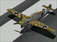
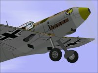
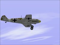
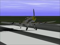
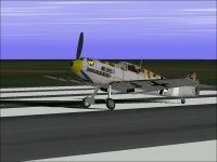
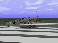
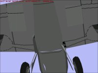
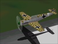
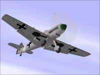
Here is what it looks like now. Note the "Openings" for the landing gear.

The process by which they are created is somewhat tedious, but the results are pretty much what I expect:

1. Take the Landing Gear Doors and rotate them until they fit somewhat aligned with the underside of the wing.
Write down the actual angles of rotation because if you do too much shuffling back and forth, you might want to restart once you have the final numbers and just do ONE rotation on each axis. Too many rotations will have the points snapping into the 0.01 foot grid and the final result may be a bit off as a result of the rounding / editing / rounding choices.
These numbers might also be useful for the Animation Sequence later.

In this case, I had to rebuild the Landing Gear Doors before I started.

2. Fill out the shape of the Landing Gear Well. In this case, I pulled another circle from the "Import Part" option and sized it to match what existed of the Gear Door. In this case, the Gear Well isn't really round because the outter edge has a flat to allow for a hinge for the OUTTER Gear Doors. I don't believe these were ever fitted in service, but the openings are still flat on the outside.

3. Using the Polygons of the underside of the Wing as a reference, adjust the points of the Gear Well vertically so they match the underside of the Wing. Sometimes you can't get an Exact match. 0.01 foot isn't very visible when the model is displayed, so an error in either direction doesn't really matter. I generally try to push the opening past flush with the wing underside because then you can't see a camo pattern move around.

4. Set this as an insignia part and glue it to the underside of the Wing facing DOWN. It should come immediately after the Wing component because nothing should be able to appear in between it and the Wing. You can texture the part if you want.

5. After Aircraft Animator, I usually change the SCASM Code to make the Gear Well and Gear Doors disappear at the same time.

- Ivan.
 

Attachments

  • Me109E_Flightline.jpg
    Me109E_Flightline.jpg
    60.3 KB · Views: 0
  • Me109E_LFHigh.jpg
    Me109E_LFHigh.jpg
    43.6 KB · Views: 0
  • Me109E_Down&Dirty.jpg
    Me109E_Down&Dirty.jpg
    41.7 KB · Views: 0
my dear Ivan....

papingo here
your me109 .air file
please check and see if the 'gyro sight' button works
(assuming that you started out with the P51.air file)
yours papingo
still busy with other stuff.....
 
Gunsights

Hello All,

I don't believe the Messerschmitt 109E would ever have been equipped with a gyro gunsight.
The typical gunsight for this aeroplane would have been something like a Revi C12 or something along those lines.

Yes, this Me 109E AIR file was derived from the stock P-51D. If the AIR file is the determining factor as to whether or not the gyro gunsight is selectable, then it is highly unlikely to work with this AIR file because I have changed the identification fields to something which is hopefully unique to this 109E.

I have no plans on making this work. Historically it would not have been accurate to have a gyro gunsight.

- Ivan.
 
Back
Top