Douglas A-20 Havoc Project

aleatorylamp

Charter Member
Hello Folks,

During an E-mail exchange with Smilo, he mentioned one of his all-time favourites,
the Douglas A-20 Havoc, so I asked him if he´d like me to make one with AF99.

His enthusiastic "Go ahead!", has prompted me start collecting the necessary information
to start building, and I found quite a variety of different versions.

So, Smilo:
You mentioned starting off with a version without the dorsal turret, so the question
here is whether there should be glass there or not. Also, I suppose you mean no ventral
gun either.

Then, there´s the question of the nose: Non-glazed with 6 machine-guns, or glazed with
no guns, or perhaps only two?

There seems to be quite a variety of possibilities on this model.

As regards engines, there´s 1600 Hp and 1700 Hp ones, so for a start we´d have to find
out which type of engines will go on the initial model. I have engines for both, from the
time we made the Baltimore series.

So, we have a plan! Great stuff!
victorious.png


Cheers,
Aleatorylamp
 
Last edited:
Hi Smilo,
Thanks for sending all that material. A great help.
What I´d managed to find is about a quarter as good!

At the moment I´m scaling the drawings, and then I´ll fire up the conveyor belt for
an initial A-20C model without the rear gun turret.

Even though it had a glazed bomber´s position in the nose, it seems to have had 4
large MG´s in the nose, two on each side, ensuring a good punch!

Cheers for now,
Aleatorylamp
 
Phase 1: Preliminary trials

Hello folks!

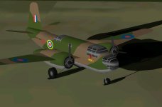
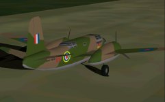
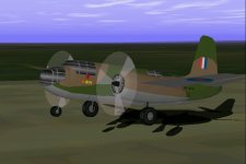
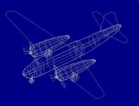
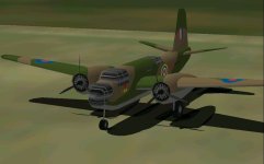
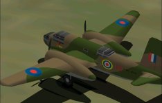
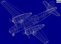
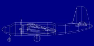
The model has progressed from the drawing board to the conveyor belt,
for a preliminary mock-up, to test for dimensions, shapes, texture spread,
and .air file performance.

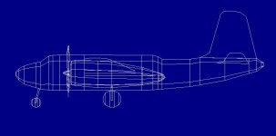
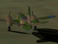
Wings and tail are as yet only 2D panels, and fuselage is still made of
structures with AF99 "oval" cross-sectiones, but will later be made of
components.

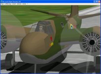
Glazed nacelle, cockpit and aft gunner´s glazed position are on the textures
for now, later to be made transparent.

However, the model has started getting the look, which is nice for building,
to get the feel.

A simple, textured and animated landing gear is also implemented, as are
engines and propellers.

According to specification, the Havoc A-20C had R-2600-23 turbocharged
engines, and with 7 machine-guns had the following top performance:

At 13000 ft: 342 mph, 1600 Hp, 2600 RPM
Sea level : 314 mph, 1350 Hp, 2600 RPM

On the model, the .air file is now giving me:
At 13000 ft: 343.7 mph, 1347 Hp, 2590 RPM
Sea level : 315.0 mph, 1602 Hp, 2590 RPM

So this seems to be quite satisfactory for a preliminary initial stage.

Now there´s at least something to show! For those interested in watching
how
the model takes shape, I´ve attached the Work In Progress model,
and included
a few screenshots. It looks like one of those coloured tin toy
airplanes 50 years ago!


Cheers,

Aleatorylamp
 

Attachments

  • Havoc prelim 1.jpg
    Havoc prelim 1.jpg
    32.2 KB · Views: 10
  • Havoc prelim 2.jpg
    Havoc prelim 2.jpg
    27.7 KB · Views: 2
  • Havoc prelim 3.jpg
    Havoc prelim 3.jpg
    38.7 KB · Views: 4
  • Havoc prelim 4.jpg
    Havoc prelim 4.jpg
    39.7 KB · Views: 5
  • Havoc prelilm blueprint.jpg
    Havoc prelilm blueprint.jpg
    65.8 KB · Views: 2
  • Havoc prelilm blueprint1.jpg
    Havoc prelilm blueprint1.jpg
    32 KB · Views: 4
A fin glu glitch, and WEP MP possibilities

Hello Folks,

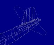
Terribly sorry, there was a glitch in the fin glu - it was a line instead of a triangle,
and caused the tail fuselage to bleed through the 2D fin ( of course)...:stupid:

Well, I fixed the fin glu, and also the fin is now 3D.
Here´s the corrected Havoc Preliminary Phase 1 W.I.P. model, and 2 screenshots!

Also, a thought about having WEP in the flight dynamics:
On the Baltimore, we had 5-minute WEP for Take-off power WEP, which was an
additional 2 inches of mercury MP over the normal max. continuous MP of 42 inches.

At the moment, I put in all the specified 44.3 inches max. MP, but I was thinking of
doing something similar as on the Baltimore, i.e. normal MP at 42.3, plus 5-minute

WEP with an extra 2 inches of MP. ...or maybe 42 plus 2.3...

Cheers,
Aleatorylamp
 

Attachments

  • Finglu.jpg
    Finglu.jpg
    32.1 KB · Views: 1
  • New fin.jpg
    New fin.jpg
    46.6 KB · Views: 0
Phase 2

Hello All,

A bit of progress: Now wings and stabilizers are 3D components, no longer made of cardboard...
I was surprised at the thickness of inner wings, and I needed several tries to get it right.

Also, the fuselage was 10% too wide, but that´s corrected now - it appears to have been quite
a slim 4 ft in width. It is still done in structures, with glazed parts on textures, but that will be seen to in the coming Phase 3.

Then, I have made a small adjustment in the engine supercharger, and have separated 100 Hp
(2 inches of mercury Manifold Pressure) to GET type-2 WEP for 5-minute Take-off power and battle, similar to what we had on the Baltimore.

This still seems a very good solution, as it makes it easy to fly with Military Power at max. throttle without WEP, and press F10 for WEP at Take-off and in battle.


Please find attached screenshots and the new model for those interested in trying it out.

Now comes the difficult building part: Fuselage conversion into components with glazed nose, cabin and dorsal gunner´s position with their corresponding framework.

Cheers,
Aleatorylamp
 

Attachments

  • Havoc-Phase2-1.jpg
    Havoc-Phase2-1.jpg
    34.5 KB · Views: 2
  • Havoc-Phase2-2.jpg
    Havoc-Phase2-2.jpg
    35.8 KB · Views: 1
  • Havoc-Phase2-3.jpg
    Havoc-Phase2-3.jpg
    36.6 KB · Views: 1
  • Havoc WIP-2 Blueprint1.jpg
    Havoc WIP-2 Blueprint1.jpg
    93.2 KB · Views: 1
  • Havoc WIP-2 Blueprint-2.jpg
    Havoc WIP-2 Blueprint-2.jpg
    33.2 KB · Views: 0
Slight improvements

Hello Folks,

I found a cleaner way of grouping/gluing the engine nacelles and wings.
Previously I´d had nacelles glued to outer wings in Wing Mid Right/Left,
and then the inner wing component in Innerwing Mid left/Right, but noticed
slight bleeds at the inner nacelle area.

It turns out that a more efficient distribution is having engine nacelles glued
to the inner wings in Innerwing Mid left/Right, where the bleed interference is
lower, and doesn´t worsen the bleeds in the outer wing/nacelle area.

Then, the stabilizer panels are now better as well, without momentary disappearances.

Also, forward engine nacelles are now grouped with the propellers in Nose Left/Right,
using the convenient Left and Right Nose/Wing templates,
and I´ve just fixed a
last-minute left spinner sequencing problem just now, which can be seen on one
of the attached screenshots...


Here´s the new Havoc WIP Nº.2 model, attached again.
I just noticed I´d deleted WIP-2 yesterday instead of WIP-1, silly mistake...
so it´s just as
well that here´s the improved WIP-2. Ever so Sorry!

Update: I noticed there´s a mistake in the engine nacelles at the upper wing
area - nacelles don´t portrude as much as I have them portruding, so that´s
the first thing to fix just now...

Cheers,
Aleatorylamp
 

Attachments

  • nacelle re-grouping.jpg
    nacelle re-grouping.jpg
    34.9 KB · Views: 2
  • nacelle grouping2.jpg
    nacelle grouping2.jpg
    38.1 KB · Views: 4
Last edited:
Wing thickness

Hello All,

With the Wing thickness problem now solved, it appears that the outer
wing/nacelle bleeds have increased.

This remided me of the Tigercat, still a WIP-model due to bleed problems.
Although the wings seemed OK, there were bleeds with wheel doors and flaps.
I´ll have to look into these again, because the model is stuck on that.

I hope things won´t get stuck on the A-20 because of bleeds, as the layout
of nacelles, wings, flaps and wheeldoors is rather similar...

Cheers,
Aleatorylamp
 
Fuselage work

Hello Folks,

Tha Havoc has now got a fuselage made of components, and just now I´m working
on the
canopy frames. The rear gunner´s is done, the cockpit now needs a floor,
and the
forward canopy frame is in the making, as you can see on the screenshots.

You can also the guide-line in the front. Then will come all the glazing work and the
glue
sequences to get the crew in. That will be a lot of fun! I like glue sequences.
It´s fun when you´ve been taught how.

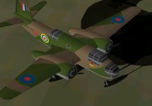
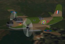
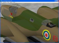
The livery is still very Martin-Baltimore-like, but the model will soon get its 5-pointed stars!

Cheers,
Aleatorylamp
 

Attachments

  • Havoc component fuselage.jpg
    Havoc component fuselage.jpg
    40.8 KB · Views: 1
  • Havoc component fuselage2.jpg
    Havoc component fuselage2.jpg
    36.9 KB · Views: 5
SSD death

Hello Folks,

Spanner in the hardwearks, I´m afraid, and it´s taking its time to put right.
At the weekend the SSD played its tedious and confusing disappearing trick
in the BIOS again.

Normally, after a few cable plugging and unplugging the hardware all got going
again, but this time it also involved OS-corruption with physical internal SSD
errors, which led to a one-way ticket into the trash-can.

I don´t know if the BIOS malfunction is the cause or the result of this hardwreck,
so things may get worse instead of better after sorting out a conventional HDD for
the OS and then retrieving development material.

At any rate, it is going to take some time until work on the Havoc can continue.

Cheers for now,
Aleatorylamp
 
Hardware Issues

Good Luck on resolving the BIOS / SSD issues.
Is it possible that you might need to replace a battery?

Sometimes hardware failures take a long time to fully manifest themselves.
It took about 3-4 years from the first sign of trouble in my old Development Machine until I had a complete Motherboard failure with smoke effects and all. During that time, there were just intermittent failures and sometimes programs didn't seem to do what they were supposed to do and sometimes the machine did not boot.

Is it possible you are having a similar problem if a drive does not detect and sometimes the drive gets corrupted? In other words, perhaps the problem is in the motherboard rather than the drive?

SSDs are fast, but I don't have a lot of faith in them. Then again, my Daughter has had a very lightweight laptop with an SSD for 5 years now and although there have been problems with the other hardware, the SSD seems to have held up.

- Ivan.
 
Hello Ivan,

It´s OK, I looked at the new battery part in the summer when the SSD started its disappearing acts after power cuts or forced shut-downs after hanging, so it isn´t the battery.

I´ve read about the older SSD´s, and it appears to be a bug in their firmware, that now has been put right for new SSD´s.

Apparently, power cuts erase the SSD SATA Port number from the BIOS, so the BIOS assigns a new one at random, and it takes quite a few SSD cable un-plugging and plugging into a different port until it coincides with the new number. Quite crazy, if you ask me - it never happens on normal HDD´s, so this idiocy has made the little faith I had in SSD´s fade away.

Anyway, I had managed to correct the problems I had this summer, but this time the SSD is flawed, even though four different SSD-scanning programs report no faults. At any rate, I´m not about to buy a new SSD, despite the improved firmware nowadays!

Now I´ve put WinXP onto a relatively new traditional big 7200 RPM HDD, and installed FS98, AF99 and AA, and things are functioning flawlessly for three days now. It isn´t as fast as before - start-up takes 58 seconds instead of 10, but so what!

The next thing is to put CFS1 back in, gather up the different add-ons like the SCASM disassembler-assembler and the special editor it needs, which will eventually get done!

Cheers, and have a nice day!
Aleatorylamp
 
Time to continue: Change-over to a solid nose.

Hello Folks,
It´s time to continue. Sorry about the long delay...

The glazed nose up front was getting very tedious, causing complications and boring delays,
so I have opted for an initial version with a solid nose, and building work has fortunately been
resumed.

Apart from the easier-to-build and elegant-looking and smooth nose shape, the tremendous
advantage of this solid-nosed version is the incredible fire power of the numerous nose
machine-guns.

The basic model itself is done, pending the rear gunner´s glass and some adjustments in the
pilot´s cabin area. When they are done, I´ll post a new WIP update.

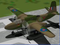
For the moment, here´s a screenshot.
Cheers,
Aleatorylamp
 

Attachments

  • Havoc-new-nose.jpg
    Havoc-new-nose.jpg
    55.4 KB · Views: 177
Hello Aleatorylamp,

Just out of curiosity, which model of Boston / Havoc is this supposed to be?

- Ivan.
 
Hello Ivan,

Here is a document I put together with the evidence for one of these models.
Apart from this one, there seem to have been some units of this kind that
served in Russia.

Note that the provisional textures on the model in the screenshots at the
moment are adapted from the Baltimore, and are not accurate for the Havoc.

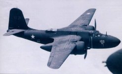
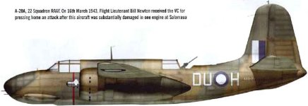
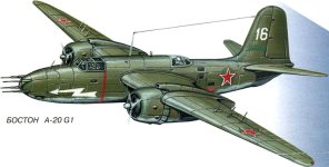
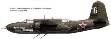
Update: Here are some screenshots of Russian and American Havocs with
solid nose and without a turret for the rear gunner, so there will be at least two
liveries available for the model.

Cheers, and have a good weekend!
Aleatorylamp
 

Attachments

  • A-20 Havoc.doc
    929 KB · Views: 7
  • havoc1.jpg
    havoc1.jpg
    21 KB · Views: 6
  • Havoc2.jpg
    Havoc2.jpg
    32.3 KB · Views: 4
  • Russian Havoc-1.jpg
    Russian Havoc-1.jpg
    64.4 KB · Views: 3
  • Russian Havoc-2.jpg
    Russian Havoc-2.jpg
    26.9 KB · Views: 4
  • Russian Havoc-3.jpg
    Russian Havoc-3.jpg
    27.4 KB · Views: 4
Last edited:
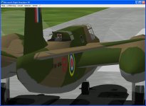
Hello Aleatorylamp,

My guess is that you probably have more choices for markings than that, though I haven't confirmed it.
By the time the early A-20G was in production, Lend-Lease had been in effect for some time and I would be surprised if some deliveries did not end up in RAF or RAAF service.

Check your service ceiling. This is not a space shuttle! ;-)
Your specifications are also for a A-20G-45 which is a much later block and equipped with the power turret in back.

- Ivan.
 
Hello Ivan,

What power would you say was correct? Do you mean those had 1000 hp engines?

I thought early units with solid nose and rear gunner position having no power turret
would be the DB-7A/Havoc II, and would have the 1600 Hp engines.

Then I found the following, so it could very probably be a "G" model:

"The A-20G, with 2850 units delivered as of Feb. 1943, had the glazed nose replaced by a solid nose with four 20 mm (.79 in) Hispano cannon and two .50 in M2 Browning machine guns. After the first 250 units, the unreliable cannon were replaced by more machine guns. Some had a wider fuselage to accommodate a power driven gun turret. Many A-20Gs were delivered to the Soviet Union. The power plant was the 1,600 hp (1,200 kW) R-2600-23."

So it appears that not all "G" models had the power turret...

Cheers,
Aleatorylamp.
 
Hello Aleatorylamp,

This is a pretty good reference:
http://www.joebaugher.com/usattack/a20_17.html

So anything in the G-5 to G-15 production blocks would match what I believe you are looking for.

I was just pointing out that the listing you had was for a G-45 which is a much later block and differs a bit in armament....
and that 725,000 feet service ceiling was just a bit too high.

- Ivan.
 
Hello Ivan,

Nice document, thanks! OK then with the 1600 Hp and the liveries on the photos.
I think I´ll provide the Russian No. 16 and the American J-DU liveries.

725,000 ft! Ha ha! For a moment I thought the .air file gave stratospheric behaviour...

I had only scan-read the text that came with the photo I found and put into a .doc file
to attach to that previous message, so I missed the Star-Wars ceiling!

OK then. I´m just working on the glue sequences for the cabin and gunner´s position.
Let´s see how it goes.

Have a nice Sunday,
Cheers,
Aleatorylamp
 
Ready for a second WIP model

Hello Folks,

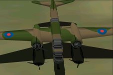
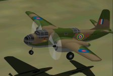
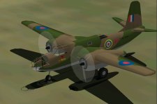
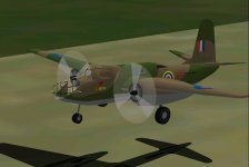
Now the fuselage has the correct shape, and there is a solid nose after issues I had with the glazed one, and I have managed transparent, inhabited cockpits for pilot and rear gunner.

It´s strange one can´t exactly replicate glue sequences for models with similar crew and cabin layouts. There are always small dimensional differences that require slight changes in the sequence.

There is still an annoying bleed from the rear cabin bulkhead that I have to see to, and some gaps at the wingroot and hairline cracks in the tail-fuselage also need attention.

Geardoors, gearwells, the deadly 6 nose-guns and ventral gun are still missing, and textures are still provisional.

Nevertheless, current progress could warrant a second WIP, so here it is, for those interested to enjoy. Comments as always, will be welcome.

Update: The cabin bleed is cured now, with re-arrangement in the glue sequence, but I have just noticed cabin-glass bleeds through wings and engine nacelles - of course, being set in Canopy High Wing, it´s not high enough to clear the wings, so I´ll have to put it into the Body Main sequence. Let´s see...

Cheers,
Aleatorylamp
 

Attachments

  • Havoc-a.jpg
    Havoc-a.jpg
    65.6 KB · Views: 5
  • Havoc-b.jpg
    Havoc-b.jpg
    51.4 KB · Views: 5
  • Havoc-c.jpg
    Havoc-c.jpg
    60.8 KB · Views: 4
  • Havoc-d.jpg
    Havoc-d.jpg
    67.5 KB · Views: 7
Last edited:
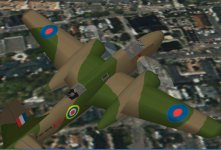
Canopy improvements: WIP Model 2a.

Hello Folks,

I managed to re-group the canopy glass for the pilot´s and gunner´s positions,
and have achieved improvements. The cabin glass is not 100% perfect yet,
but it´s much better. One Glue-template angle here played a key role.

Also, I think there was an FS98 .air file in the WIP 2 attachment I uploaded this
afternoon, but that´s now superseded by this one.

Here is a WIP 2a Havoc model version, now also including source files should anyone
feel inclined to have a look inside.

Enjoy, and Cheers,
Aleatorylamp.
 
Back
Top