Douglas A-20 Havoc Project

Update: WIP model No. 3

Hello Folks,
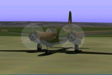
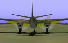
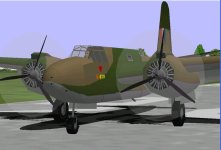
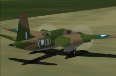
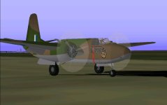
There has been some progress in the construction of the A-20 Havoc.
AF99 Parts Count is now at 145.4%, and the model is slowly approaching completion.
Now it has flaps, 6 nose guns, the ventral gun, wheel doors and wheel wells.
Attached is the WIP-3 model and 2 screenshots, and as before, it includes source files.
The following work is still pending at the moment:
> eliminate some flap bleeds
> general textures
> removal of a few hairline cracks
> adjust dp files
> ...and anything else anyone would like to point out.
Hopefully I can finish the model for Christmas or New Year.
Meanwhile, enjoy the WIP update!
Cheers,
Aleatorylamp
 

Attachments

  • A-20 Havoc.jpg
    A-20 Havoc.jpg
    38.2 KB · Views: 5
  • A-20 Havoc-2.jpg
    A-20 Havoc-2.jpg
    35.2 KB · Views: 4
Now with air-intake scoops. Update: WIP-4 Model

Hello folks,

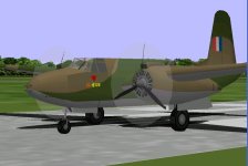
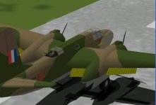
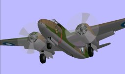
I´ve managed to complete the model with the supercharger scoops on
top of the engine nacelles, and also reduce flaps and geardoor bleeds considerably.
It´s going rather well, so here are a few new pictures, and also a WIP-4 update.

Textures, SCASMed Virtual Cockpit and hairline cracks are still pending.

Update: Oops! I just saw flaps are of the wrong type and will have to be cut out
of the wing instead of fitted beneath.

Cheers,
Aleatorylamp
 

Attachments

  • A-20 Havoc-3.jpg
    A-20 Havoc-3.jpg
    46.4 KB · Views: 3
  • A-20 Havoc-4.jpg
    A-20 Havoc-4.jpg
    46.3 KB · Views: 4
  • A-20 Havoc-5.jpg
    A-20 Havoc-5.jpg
    51 KB · Views: 4
Last edited:
Hello Aleatorylamp,

Fitting plain flaps instead of split flaps is going to be a serious pain this late in the game.
One of the nice things is that texturing will be simplified over split flaps.

- Ivan.
 
Hi Ivan,

Yes, as nicely as it was going and now it isn´t!
I thought I´d been lucky with the split flaps. What a goof!

With a parts count now of 149.4%, plain flaps are going to be, like you say, a pain.
Wheels, struts, fuselage, wings, tailplane, canopy frames, windows, have eaten up all
30 components, and none of the 28 structures left can be converted.

Flaps will have to be individual panels each, which in itself should be no problem.
Hopefully the outer wings with cut-outs now will not have textures bleeding over inner
corners with extended flaps.

I had already reduced nacelle bulkhead vertices from 12 to 10 to free parts for the
scoops, which went fine, and now I´ll have to eliminate maybe 2 bulkheads from the
nicely rounded fin structure, which is a pity.

Another bore is that on the real plane there were bits of wing on trailing edge nacelle
sides adjacent to flaps, and maybe those will have to go.

Anyway, let´s see how it goes.
Cheers,
Aleatorylamp
 
Hello Aleatorylamp,

I had figured out pretty early on when I started working on my own A-20 Havoc many years ago that it wasn't going to be a simple AF99 project with the level of detail that I wanted. My main problem was that the references didn't seem to agree in basic dimensions. Many dimensional drawings and even specifications in the manuals were simply wrong.... More on that later if you are curious. My visual model hasn't progressed to any great degree, but the amount of documentation I how have is at least 4-5 times what I was working with back then.

Remember where we started with the Eric Johnson P-39D? That project also made a pretty similar mistake in putting plain flaps in a P-39 though of course it is much easier to fix that kind of a goof than to ADD plain flaps afterward.

Good Luck.
- Ivan.
 
Plain flaps on the way

Hi Ivan,
I just had a look at my Russian Airacobra - fortunately it´s OK with its split flaps. I´d forgotten about that, although I do remember deviations from the correct proportions that we managed to so successfully correct. That was a nice and interesting project, and yours came out very well too, in the several variants you provided!

I had checked the numerous and detailed Havoc drawings Smilo had sent me, and was able to discard a few inconsistent drawings I had found at the time. Such inexactitude seems to be widespread on several sources, most probably inherited from sites 20 years ago, when information wasn´t abundant on the internet, and much was inexact.

Anyway, as regards the complications of Havoc details: I think I´ll sacrifice the details of the 4 wing-root stubs on engine nacelle sides. At 3 parts per stub, I´d need 12, and I definitely won´t have those, although I doubt the model will suffer very much from their loss. One thing I´m happy enough about right now, is that after doing the wing cut-outs, it´s thankfully not bleeding any texture triangles over the inner corners.

Update:

Main Parts for plain flaps fit into parts count very well, without simplifying the fin or the intake scoops, but triangular edge fillers on the flaps create bleeds, so they must be left out. This will cause some gaps when seen from the side, but can´t be avoided. Now I´m on the glue sequences so flaps won´t bleed through wings or nacelles. It´s not going too bad.

Cheers,
Aleatorylamp.
 
Last edited:
Hello Aleatorylamp,

The EJ Airacobra project was a serious learning experience in flight modelling. It is a great example of how things changed between FS98 and CFS AIR files. The center of lift offsets were meaningless because everything was done via moments.
It took a lot of effort to get the instability where I wanted it to be.....

Regarding the mistakes in A-20 drawings and specifications:
The problem came about because of the design of the aircraft.....
Everything is the same length from Station Zero on back, but the dimensions changed depending on the nose that was fitted and THOSE varied a lot in dimensions.
The manual would often list a single overall length but the drawing that accompanied that specification did not match the length that was listed because the attack nose and glazed nose were not the same length.
Of course as new versions were built, there got to be many more variations in length and shape.

The kind of detail I was thinking about was 3D Cowls that I could not put on the Mitchell for lack of resources.

- Ivan.
 
Plain Flaps working!

Hello Ivan,

I see. Then it´s just as well you mentioned the different lengths depending the type of nose, so I´ll check the length for the solid nose before posting another WIP. I also noticed small differences in the placing of the 4 nose-tip machine-guns, and I´ll check how the RAAF Havocs had theirs.

Anyway, I finally got the plain flaps in, and with no bleeds! I went scrounging for free components and got 4, and managed to separate outer wings into mid- and outer components, also getting outer flaps into components. As a result, the glue-sequence works very well, and the filler-triangles are back in. All rather satisfying!

Now I only have to re-map the fuselage textures, as one of the components came from the fuselage, and this has upset the original mapping. Anyway, it´s working!:wiggle:

Cheers,
Aleatorylamp
 
more free parts

Hello Ivan,

The workshop was working a night shift for the flaps corrections, and now they are busy spraying the Aussie camo scheme. This version also has shorter air intake scoops on top of the engine nacelles, which will be a help too, as it saves quite a few parts.

Re. Havoc lengths, depending on the different noses, the blueprint dept. has seen following specs:

45 ft 11 in (this one could be discarded)
47 ft 4 in
47 ft 11 in
48 ft (currently on the model)
48 ft 4 in

All quite confusing. Early glazed nacelles seem to have been shorter than later glazed ones, and also shorter than the solid ones, so probably length can stay as it is.

I´ve also seen early glazed nacelles painted over, with field adaptations of 3 and 4 nose-tip MG´s, apart from the two bigger cannons on the sides below them further aft.

More later....
Cheers,
Aleatorylamp
 
Hello Aleatorylamp,

I believe ALL of the lengths you listed are correct for SOME model of Havoc / Boston / DB-7. That is why it makes more sense to work from the station diagram than a "dimensional" drawing.

The dimensions that I had the hardest time finding was the relationship of the Thrust Line to the Fuselage Reference Line or the Mean Aerodynamic Chord and the location of the top of the Fuselage in relation to the FRL.

- Ivan.
 
Lengths clarified!

Hi Ivan,

I went rummaging in Smilo´s Havoc docs, and found two separate folders with detailed
drawings of the 2 Havocs with glazed and solid noses. It turns out the 48 ft correspond
to the early glazed nose, which was the design I originally intended to produce. Then, the
solid nosed version length is 47 ft 4 inches. No problem now, I can easily shorten the nose
components.

Further to your message just now about engine thrust-line difference to the fuselage line,
I had already noticed the 2-degree positive inclination of engine thrust-lines marked on
Smilo´s drawings, but I´m afraid that will be impossible to do because of the engine-nacelle
structures.

Parts count is at 148.8%, with 30 copmponents and 27 structures, and there´s unfortunately
no possibility whatsoever of freeing any further components for two slanted nacelle-fronts,
which would then get slanted propellers and slanted propeller blurs and discs, discarding the
AA ones, but that will hardly be noticeable anyway.

Cheers,
Aleartorylamp
 
Hello Aleatorylamp,

I would strongly suggest that you DO NOT shorten the nose on your A-20.
....Or if you feel that you MUST, then do some more research to make absolutely sure that the length corresponds to the version you are trying to represent.

Length differences between the early A-20 version and late A-20 versions are NOT the same.

I also decided not to represent the inclined thrust line because it is almost not noticeable. The question was really the location of that thrust line in relationship to the fuselage. The slight inclination gave a slight bit of flexibility but I still needed to know the location of the thrust line / centerline of the nacelle before building it.

- Ivan.
 
Good morning, Ivan!

Thanks for your words of caution. The diagrams with the 47.4ft length solid-nosed
variant refer to the A-20G. The diagrams with the early glazed nose variant are from
the 48ft A-20C.

Well... and the drawings of the Aussie DU-G, DU-K and DU-H variants are all A-20A
models, so I think I´ll follow your advice and leave the model as it is. The 6-inch
variation will go unnoticed anyway.

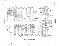
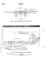
Here are 2 of the diagrams, which show thrust and the fuselage ref. lines. Hope it helps.

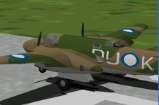
Here´s also a screenshot showing the new flaps. Ignore the lettering - I´m still
working on the textures.

A fine St. Nicholas celebration to all.
May you find some nice goodies in your slippers!

OK, then!
Cheers,
Aleatorylamp
 

Attachments

  • A-20Gmanual - Page_1.jpg
    A-20Gmanual - Page_1.jpg
    71.4 KB · Views: 5
  • A-20Gmanual - Page_2.jpg
    A-20Gmanual - Page_2.jpg
    39.3 KB · Views: 5
  • A-20 new flaps.jpg
    A-20 new flaps.jpg
    46.7 KB · Views: 5
Hello Aleatorylamp,

I have those drawings also. I believe they are from the A-20G Erection & Maintenance Manual and I have a copy of that.
The problem is that I believe those dimensions are actually not correct. I actually have much better drawings in a couple large PDF books.
Of course with so much conflicting data, one has to choose what to believe.
I would suggest if you have not already done so, you should read the "Design Analysis for the A-20".


From what I can tell, the Bomber noses were slightly shorter than the Attack noses and not the other way around.
This seems to be supported by photographs as well at least by my eyeball. There are going to be exceptions because there were several variants of each kind of nose.
The A-20C is listed as both 48 feet 0 inches and 47 feet 3 and some fraction inches. I choose to believe the shorter length is accurate.

We do not have to agree in our conclusions. That is one of the things that makes flight simulators more interesting.

- Ivan.
 
Surprise inside the slippers for St. Nicholas

Hi Ivan, hello Folks,

Very interesting, Ivan, thank you very much. I´ll go with that research information then!
My criteria is not as reliable as yours, so I haven´t changed the nose dimensions.

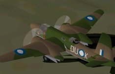
Attached is the A-20 Havoc WIP-5 model. Smilo will be rather pleased, I wager, with the
progress upto now:

Plain flaps are on, a few cracks are gone, and the aircraft now has preliminary textures for
the Aussie DU-K, which incidentally, seems to have had the longest list of successful sorties.
I´m still working on the gear-door glue sequence which presents some short bleeds from
shallow angles.

Here are some pics and the aircraft with source files should anyone be interested.

Cheers,
Aleatorylamp
 

Attachments

  • Wip-5 a-20 havoc.zip
    503.5 KB · Views: 3
  • Havoc WIP5-1.jpg
    Havoc WIP5-1.jpg
    41.1 KB · Views: 4
  • Havoc WIP5-2.jpg
    Havoc WIP5-2.jpg
    32.2 KB · Views: 7
  • Havoc WIP5-3.jpg
    Havoc WIP5-3.jpg
    29.5 KB · Views: 7
  • Havoc WIP5-4.jpg
    Havoc WIP5-4.jpg
    31.7 KB · Views: 6
Hello Aleatorylamp,

Making a mistake because YOU goofed is one thing.
Making a mistake because you depended on MY research being correct is much worse.....
You should confirm numbers rather than just accept them. You don't know how sloppy I can get.

- Ivan.
 
Hello Ivan,

At the end of the day we do what we can with what is available, and make
the decisions we feel are correct despite contradictory or inexact information.
Small differences go unnoticed anyway, so I´m not worried.

The Havoc model is at present as good as I can get it. There is still some texture
smearing under the tail in the last WIP-5 I sent, which needs correcting, and I
intend to texture the area surrounding the nose guns. That, and the hairline cracks,
and it will be done!

Cheers,
Aleatorylamp
 
Your description of design choices seems like the best guide thus far.

Good Luck!
- Ivan.
 
Hi Ivan,

After your warning of not shortening the nose, and seeing that the drawings of the solid
nosed unit (47.4 ft length) corresponded to the Havoc A-20G, I noticed the A-20A
frame-strut pattern on all pictures of the Aussie Havocs with solid nose.

This could mean that either the glass had been painte over, or perhaps more probably,
the plexiglass windows had been substituted for metal plate, arguably to offer more
protection than plexiglass for the machine-guns inside.

Update: I just got the wheel-well bleed fixed. Strangely enough, altering the glue sequence
and grouping only made it worse, and it was a matter of changing the glue angle to cover
wheel and wheelwell from the geardoor, although the wheelwell is in another group.
Then I put in the kind of skid fairing there is at the back, but only 2D as 3D "V" went
beyond parts-count limit.

Anyway, as soon as I get the textures how I want them, I´ll be uploading the model.

Cheers,
Aleatorylamp
 
Last edited:
Hello Aleatorylamp,

From what I have been able to find there actually was never a version of the A-20 that was 47.4 feet in length.

I may of course be incorrect, but the A-20A would have been 47 feet 7 inches.
The A-20C MIGHT have been 48 feet 0 inches but I believe it is more likely it was around 47 feet 3 5/8 or 47 feet 4 inch.
There is enough conflicting information to argue for either dimension.

My belief because of other conflicting evidence I have seen is that the 47 feet 4 inch length listed in the A-20G E&M manual is simply incorrect.

You are thinking of reasons that might explain how the dimension might be correct. I believe you are wasting your time and it is simply a mistake carried over from prior versions of the manual.

- Ivan.
 
Back
Top