Electro Power for small aircraft and drones

Hello Aleatorylamp,
I think you are way too worried about exact values. I am absolutely certain that if I reworked the P-40N propeller a second time, the exact numbers would not be the same. The point of the screenshots was just to show what to look for as far as problems and what the solution was. The number that you put in did not need to match exactly as long as it addressed the problem. If it were an issue, I could have just sent you the latest copy of Hubris AIR file.

The issue with the Airacobra Power Coefficient table was that the NXT is both lower powered (really lower power coefficient) but goes substantially faster down low (about 80 MPH faster). It did not have enough power to hit the 40 Degree curve with the lower power coefficient and was running out of efficiency with the 35 Degree curve.
That was the ONLY thing that really needed fixed. The rest of it was a matter of editing the Propeller Efficiency curves in such a way that the transitions between different angles didn't drop so much. As I stated earlier, ALL interpolations are bad, it is just a matter of how bad and where it is bad.

- Ivan.
 
Hi Ivan,
Thanks for explaining the screenshot thing, but I wasn´t complaining.:cool:
It´s better without your latest copy of the Hubris .air file anyway, because I wanted to see what I could do and what I would find out.

Using the Airacobra-derived Propeller Graph tables:
Strategy using the specified, off the shelf 75 inch diameter Propeller, and Boost Gain slightly reduced from 2.657 to 2.65.
1) Increase Torque graph OR lower Friction Graph - makes no difference which - to bring 500 ft Power up from 330 to 350 Hp.
2) Lower the entire 35 and 40 deg. Power Coefficient curves to raise the low S.L. and Reno altitude performance. This provides a perhaps misleading sense of success: Anything between 396 and 416 mph can be achieved easily. So, when 402.6 mph came out, I left it there.
3) Obviously, attack the 45 and then 50 deg. pitch curve in the Power coefficient table and raise them a lot, to lower the excessively high performance around C.A.
There is now a large gap between the 40 deg. and 45 deg. Power curves, which looks rather odd, I must admit. Also, now the Governor has stopped selecting the 50 deg. curve. needing only the 45 deg. curve for interpolation, which seems to work.
I suppose there is not enough power available to use the 50 deg. curve?

Update: I further lowered the 35 deg. curve slightly, and then, in the Efficiency Tables, I raised some J-factor positions in the 35 deg. and 45 deg. curves, gaining 1, 2 or 3 mph upto 5500 ft, and then I lowered some positions in the 45 deg. curve, reducing 1, 2 or 3 mph above 10000 ft.
Now there is a larger gap between the 35 and 40 deg. Efficiency curves...
The attachments show the tables with highlighted 45 deg. curve. They are squashed left-right a bit for viewing.
Latest results:
500 ft: 350 hp, 371.6 mph, 39.5 Hg, 37 pitch
1500 ft: 353 hp, 375.7 mph, 39.5 Hg, 37.3 pitch
2500 ft: 357 hp, 380.5.7 mph, 39.5 Hg, 37.7 pitch
3500 ft: 361 hp, 388.5 mph, 39.5 Hg, 38.3 pitch
5300 ft: 367 hp, 402.7 mph, 39.5 Hg, 39.3 pitch <<<< about right, I´d say, as per your suggestion.
6500 ft: 372 hp, 416.8 mph, 39.5 Hg, 40.1 pitch
9500 ft: 384 hp, 425.3 mph, 39.5 Hg, 40.7 pitch
12500 ft: 396 hp, 433.0 mph, 39.5 Hg, 41.5 pitch
14500 ft: 405 hp, 436.6 mph, 39.5 Hg, 42.0 pitch
16000 ft: 411 hp, 443.0 mph, 39.5 Hg, 42.5 pitch <<<< already getting too fast
16800 ft: 415 hp, 447.1 mph, 39.5 Hg, 42.8 pitch
17500 ft: 417 hp, 451.0 mph, 39.5 Hg, 43 pitch << Power and speed peak.
18000 ft: 407 hp, 450.3 mph, 38.6 Hg, 42.9 pitch << All starts going down.
18500 ft: 399 Hp, 448.7 mph, 37.8 Hg, 42.9 pitch

Cheers for now,
Aleatorylamp
 

Attachments

  • Screenshot (284).jpg
    Screenshot (284).jpg
    67.5 KB · Views: 5
  • Screenshot (285).jpg
    Screenshot (285).jpg
    86.1 KB · Views: 2
Last edited:
Hello Aleatorylamp,
I believe your approach was very strange, but you got about the same results as I did, so who is to say that my process is the only valid one.
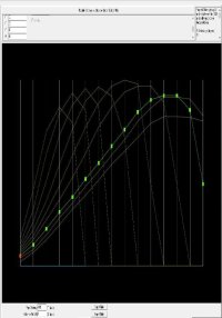
It is interesting how we took entirely different approaches to getting to approximately the same performance. I believe the Propeller Efficiency graph you are using is strange because the maximum efficiency for this propeller is achieved at 35 Degrees and is quite low after that.
I attached screenshots of the graphs for my version based on the Airacobra propeller as a starting point.

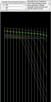
The Horizontal Red Dashed line in the Power Coefficient graph is 0.10500 which is slightly below the engine's Power Coefficient at 5,000 Feet.
The Speed at which it should have been switching from 35 Degrees to 40 Degrees was around 370 - 380 MPH which is around J=2.0.

- Ivan.

NXS-CobraV1-512.jpgNXS-CobraV1-51.jpg
 
Hi Ivan,
Yes, I do admit my approach is very strange, especially as can be seen from the large gaps between the 35 and 40 deg. Power curves and the 40 and 50 deg. Efficiency curves. I don´t think anyone would make a propeller shaped like that... it would indeed look rather odd - the mind boggles.

But... is is the best I can manage, and everyone in the workshop here is wearing masks because of the aluminium dust accumulating in mounds on the floor, and they have to wade through them because the cleaners have resigned. I hope the foundry and sanding machine workers don´t run away as well...

There is still something I can´t get my head around - sorry:
"The Horizontal Red Dashed line in the Power Coefficient graph is 0.10500 which is slightly below the engine's Power Coefficient at 5,000 Feet.
The Speed at which it should have been switching from 35 Degrees to 40 Degrees was around 370 - 380 MPH which is around J=2.0."

I can see the Governor in the Beckwith Test Gauge moving up and down the pitch angles in decimals,
Stupid question: I take it that engine Power Coefficient is not propeller Power (required) Coefficient. How is it obtained? I was looking through this thread because I seem to remember something mentioned about it, but can´t find it.

Attached is my Nemesis NXT .air file with Airacobra-derived propeller tables.
If it doesn´t put you out in any way, I was wondering whether I could ask you to make your two Excel graphs for it, so I can inspect them to compare them to your ones, to see if I can gain a bit more insight.

Thanks very much indeed... and sorry to to bother you...
Must get dinner...
Cheers,
Aleatorylamp
 

Attachments

  • Nemesis NXT .air file.zip
    3.9 KB · Views: 2
Hello Aleatorylamp,
I have had much less time to myself than usual over the last couple of days. There are a few administrative tasks such as changing our health insurance and the usual pattern that Anna Honey generally comes back from some trips a bit sick. It means I actually have a few things to do. I had to do some lunch prep before the last post I made.

My mistake, I should have written "Propeller Power Coefficient" at 5,000 Feet.
I was thinking mostly of the varying engine power which is why I wrote what I did.
That graph is always Propeller Power Coefficient though what happens depending on the position on the graph may have some interesting results. If a series goes Negative, it means that instead of the propeller driving the air backwards, the AIR is driving the Propeller. Think terminal velocity dive and propeller over speeding.

I just downloaded your newest AIR file and will generate some spreadsheets and post them when I am done. Dinner may be soon, My Son and Anna Honey are both out picking up some carry out right now.

- Ivan.
 
Hello Aleatorylamp,
Finished dinner a little while ago and generated a couple spreadsheets.
It took me a little while to look them over because I figured the idea was to provide you with some useful information that you could act on.
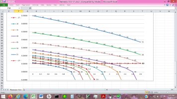
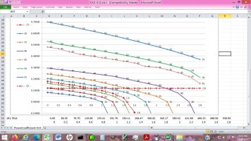
The first attachment is the Power Coefficient graph.
The Horizontal Red Dashed line represents my estimate of your NXS power coefficient at 5000 feet.
My spreadsheet for this calculation only handles multiples of 2500 Feet, so I used your HP reading for 5300 Feet. It may be 1-2 HP off but that probably is not significant.
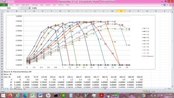
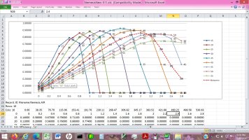
The second attachment is your Propeller Efficiency graph.
The Red Dashed line represents 42.5 Degrees.

I am not sure if this is intentional, but at the moment, your speed at higher altitudes is limited by the Efficiency curve for 40 / 42.5 Degrees and there is not enough engine power to get to 45 Degrees. I am not sure if you consider this to be a problem or a feature.

- Ivan.

XXX-512.jpgXXX-511.jpg
 
Hi Ivan,
I woke up at 2.30 a.m. and couldn´t sleep.
Thanks for the clarifications and for your efforts in providing the two graph tables for my current Nemesis NXT flight model.
I must say you deserve a medal 🥇 for your patience and a cup for your explanations.🏆
OK... I´ll print out the 2 graph tables after breakfast so as not to make so much noise, and now I´m going back to bed - I found the option to do a decent print-out in the top right hand corner of the viewer right here on this page.
So,
Cheers for now
Aleatorylamp
 
Hi Ivan,

I have some time - I wonder how much... I´d missed answering your question:
I am not sure if this is intentional, but at the moment, your speed at higher altitudes is limited by the Efficiency curve for 40 / 42.5 Degrees and there is not enough engine power to get to 45 Degrees. I am not sure if you consider this to be a problem or a feature.
Yes, it was intentional. Now, if it is a feature or a flaw, I wouldn´t know in view of your remarks... All I wanted was to lower speed at higher altitudes, and I saw that it worked, because now it would require more power to use the 45 deg. graph, which would make it faster than it already is.

My five minutes have gone, and I have to eat lunch... I thought I´d get some more time.
Thanks again for the graph tables! (y)
Update:
1) The 35 deg. curve is the highest because I wanted to pull up the 37 deg- interpolation in order to raise speed lower down, I couldn´t do it with the 40 deg. curve because that was going to affect other speeds higher up.
2) The 42.5 deg. interpolated dotted line curve peak has a strange position because I needed to bring down altitude speed as much as possible.
Anyway... not an easy thing to do by any means.

P.S. I´ll see about learning to use EXCEL spreadsheet... Also fights brain fog?
PPS: My previous message: It wasn´t the printer option but the download option that allows a decent print-out.

Cheers,
Aleatorylamp
 
Last edited:
Hello Aleatorylamp,
I had not seen anything that seem to need a response from me. As I stated earlier, you and I do things in a radically different manner. I already pointed out the issues I saw and you know they are there, and are apparently using them to accomplish a purpose, so no further comment is necessary.

Life has been interesting in other ways as well. This morning, Anna Honey was using an electric hedge trimmer and cut the extension cord that was supplying power to the device. It means I need to cut off the couple feet past the mangled section of cord and move the socket end that I installed a little closer in. This is not the first time she did this, so the socket is not the original and I can just unscrew the pieces and rewire the cord. Of course I will test it afterward.....
Now to find a bright place to work.

- Ivan.
 
Hello Ivan,

I hope you are had a nice Sunday. We went to the Farmers´s market for my much needed bio beggies, and to a handicraft fair in a village nearby on a mountainside near some the woods. We found nothing interesting to buy but it was a nice walk - rather hot for this time of the year: 33 deg. centigrade.

I was constantly being interrupted yesterday, even after lunch... So:
Re: My modifications to the Airacobra derived propeller graph tables:
Yes, I know what you mean. Reflecting on it, had I at least been able to get 5 or 10 mph difference out of such a destructive maneuver to the curves, perhaps it could have been justifiable, but this damage to the governor is hardly worth while for such a small 1-3 mph difference. 🤯

So, I´ll revert back to your attached .air file, and for a possible upload, I´d rather use one of your .air files, (crediting you for it). Which one would you prefer?
I´ll have to see about a wing-root trailing edge fairing bleed first though.

P.S. I´ll see about learning to use EXCEL spreadsheet... Also fights brain fog?
I didn´t know this was so difficult for graphs, but we´ll see.
For the moment, like for you, my FDE can´t find the path to CFS1 planes. Strange, because it does find CFDS2 planes, and both simulators are not placed inside the default Microsoft directories.
AirEd shows chart columns and lines in numbers, but they can only be copied to the Clipboard, to be used only by itself on another .air file.
Also, in the Hexadecimal display window it offers, you can only select and copy separate columns for angle-number, angle-value, and ascii equivalent.
Finally, AAM allows exporting the whole .air file in ASCII but won´t show graph table content, and also allows the entire hexadecimal display window to be copied.
However, how to get the data into a spreadsheet without having to enter each value by hand is quite another matter.
I hope you didn´t have to enter everything by hand for the two extra graph table images you kindly sent!😰

Regarding your Wifes´s adventure with the electric hedge trimmer extension cable - it´s not the first time I´ve heard that happening to friends in their gardens with their lawn mowers, but I had an unbelievable experience with a cleaner from a village ages ago: One day I got home and found the vacuum cleaner roll-out cable cut with a knife. The cleaner reported in a terrified tone, that it had started making sinister, unearthly noises, after which it suddenly exploded... quite a laced description of events on her part, of course, but poor woman, she obviously thought it was the devil´s doings, and sabotaged it.

Cheers,
Aleatorylamp
 
Hi Ivan,
P.S.
Incidentally, in my last message I wasn´t implying I now expect help or indications on the use of a spreadsheet, never fear!
It was just to indicate I´m on the way... I hope. Not to worry! I also found quite a few tutorials.
Cheers,
Aleatorylamp
 
Hello Aleatorylamp,
If you intend to use one of the AIR files I worked on, perhaps I should send you the revised NXT file that was based on Airacobra propeller tables as I modified them. I did a few other modifications as well. I was doing non-NXT / Hubris related things yesterday and also trying to do some organizing since it is fairly obvious my Development Machine probably is not coming back.
This old laptop seems to have a few problems with installing one particular Windows patch and seems to spin like mad when there is no user activity on the computer.
Power extension cord is now repaired.
I was looking over data in the Stock Power Coefficients spreadsheet and found that I should have had data to fill in some of the entries. With all the recent work on NXT, I realized that I had only spent a fraction of that time on any of my own propeller tables, so I should probably look them over now.
Did you know that the Macchi C.202 Folgore and C.205 Veltro had nearly identical power coefficients at 500 Feet even though the engine differ by about 250 HP?

As for populating the spreadsheets, I wrote some C programs years ago when I first started working on Ivan's Propeller Factory.
These programs are not greatly different from what you wrote to edit AFX files way back.
My translation programs do have a slight flaw though: They will truncate values after 6 decimal places. I don't believe this is all that important because Power Coefficients and Propeller Efficiencies are not particularly meaningful past the 6th decimal place.
Maybe I will eventually fix this and maybe I won't.

Need to join the rest of the family for dinner.
- Ivan.
 
Hi Ivan,
I´m sorry to hear about your Development Machine, and I hope the old laptop problem can be solved soon.

Thanks very much for your offer! Yes indeed, I´d be happy if you would like to send me your revised NXT file based on Airacobra propeller tables as you modified them. I´m sure your further modifications will be in order too. I often have problems defining wing aerodynamics and control surface sensitivity, so that would be fantastic for an upload after I get the trailing edge wing-root bleed sorted out.

Interesting, what you say about your Folgore and Veltro machines. I looked at their Wikipedia specs just out of curiosity. With basically the same airframe, the more powerful Veltro seems to have been 29 mph faster but considerably heavier, so the two flight envelopes would possibly be quite similar, especially at 500 ft where the air is denser.

Re. Spreadsheet: I´ll have a look at the format used to import a propeller table, and see if I can do a text file organized in decimals for the task. From what I can see in AAM, the 6th decimal place has a negligible effect on any of the curve positions.

Something interesting happened yesterday, which I must mention after my comment about J.W. Beckwith´s AirWrench program not working for CFS1. For the record, this seems to be not entirely true.

Most sites stated that AirWrench only worked with FS2002, FS2004, FSX, CFS2, and CFS3, but there was one site that mentioned it was good for CFS1 too.

All CFS1 planes I tried running through AirWrench in the past, without exception summersaulted violently in the sim, leaving nothing as reference to work on for repair. However, if the model is imported into CFS2 first, and re-worked with AirWrench there, the resulting .air file and Aircraft.cfg can be transferred into CFS1 and re-worked with AirWrench again. Then it will fly in CFS1! Most of the data in the Aircraft.cfg is of course superfluous for CFS1.

I found out because I wanted to have a closer look at the propeller tables generated by AirWrench, and put the Nemesis NXT into CFS2 to re-work with Airwrench. The generated tables looked much like the traditional FS style. Then I had the idea of putting that model into CFS1, and AirWrench generated flight dynamics which allowed the plane to fly! However, it was difficult to get the desired speeds, until I figured out how to regulate Drag in AirWrench, which is not mentioned in the manual and is named differently.

Anyhow, an interesting exercise too, although I would wager you aren´t interested in AirWrench at all, just as I haven´t the slightest interest in any (other) AI program like Microsoft Copilot or suchlike...

Cheers,
Aleatorylamp
 
Last edited:
Hello Aleatorylamp,
I never said that the Folgore and Veltro were nearly the same. I just said their propeller power coefficients were nearly the same. That explains why when the Folgore were upgraded to Veltro standard after the war, the propeller looked the same. All currently existing Veltro are actually converted Folgore.
I played around with AirWrench years ago but never had much trust in what it was doing to the Air file. I was thinking that if the tool had to be used, it made more sense to see the changes it made to the Air file and copy only those changes. I figured that for me, it made more sense to just learn how to do things the best I could. The tool is a masterpiece in any case and shows the author has a much better understanding than I do.
This is not AI and it is not magic. It is just a bunch of math formulae.

As for which Nemesis Air file is better, I believe both have their issues. Your NemesisNXT.air matches the model better (I hope) but there is some strangeness in the engine related tables and I believe there are some parameters that are outright wrong. My Hubris Air file is built for a different drawing than what you used for your model and neither Air file is well refined.
Just as a matter of comparison, note that yours has a ground angle of 10 Degrees while mine has a ground angle of 8.3 Degrees. I have no idea which is actually correct, but mine matches the drawing I scaled dimensions from.

- Ivan.

NXT_QuarterInch.jpg
 

Attachments

  • NemesisNXT-AIR.zip
    4 KB · Views: 1
Hello Ivan,
Thank you very much for your .air file! I think that it is better for an upload than mine.

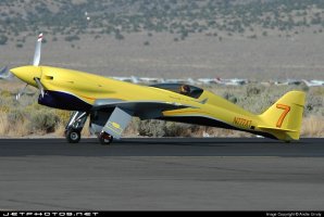
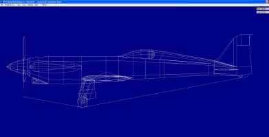
Regarding the angle on the ground, I thought this drawing showed the landing gear to be proportioned rather small compared to the photos. I couldn´t find any drawings with landing gear, so I had to use photos. Attached is a screenshot of the AF99 Blueprint side-view, and a side-view photo of the NXT on the ground, where I get the impression that the landing gear looks bigger and that the fuselage angle looks a bit greater. I´ll check the fuselage angle on the model again.

Re: Folgore and Veltro: You had asked: "Did you know that the Macchi C.202 Folgore and C.205 Veltro had nearly identical power coefficients at 500 Feet even though the engine differ by about 250 HP?", and with my answer, I was speculating on the reason for this. I didn´t know that they probably had the same propeller, but that would be the answer then.

Re: AirWrench: I thought a bunch of math formulae would qualify as AI, but of course, AI is supposed to learn things, which is not the case here. In any case, I agree that it is a masterpiece, and I´m glad I found a way to get it to work with CFS1, which seemed to be out of the question before.
I ran the NXT .air file through AirWrench, but at the moment, the Autopilot never stops porpoising, so I have to tune by hand using elevator trim. However, once it is stable, it easy to slew to different altitudes to check speeds and power. The speeds I managed to get from it are 440.4 mph at 17500 ft, 414.2 mph at 5500 ft and 393.2 mph at 500 ft. (the last two would be a bit high though...)

Incidentally, I contacted Jon Sharp, asking about speed specifications we are missing, and got a quick reply asking whether I was going to market this or if it was just for myself. I answered I never sell my models and that they are always freeware, but I´ve received no further answer, so I presume it is a case of information that is kept secret.

OK, then... Cheers for now,
Aleatorylamp
 

Attachments

  • Nemesis NXT Kit #1-Dan Wright-1.jpg
    Nemesis NXT Kit #1-Dan Wright-1.jpg
    192 KB · Views: 2
  • NXT Screenshot.jpg
    NXT Screenshot.jpg
    150 KB · Views: 2
Last edited:
Hello Aleatorylamp,
I believe what I sent you is a pretty good basis for a releasable flight model, but it still needs a LOT of testing and tuning.
I believe the handling is still not so good at this point. One of the things you should address is the Cockpit viewpoint in the Fuselage record. I adjusted it a bit when I adjusted the ground angle the model enters the simulator but I didn't try to put the viewpoint between the pilot's eyes as it should be.
I only commented on the ground angle because it is an obvious difference between Hubris and Nemesis. I sent you the profile image so you could see where I got my dimensions for the Hubris Air file. I do not claim the drawing is particularly accurate.
If you did your research, your dimensions are probably better than mine, but beware: not all the drawings out there are accurate.

Regarding Folgore and Veltro, I believe it is just coincidence that the Propeller Power Coefficients come out so close. You can actually get away with quite a large variation of engine power with the same propeller. Besides, the Propeller is actually part of the calculation of Propeller Power Coefficient.

I have never developed flight models except for FS98 and CFS1, so when I tried AirWrench it had to be with CFS1. It worked fine from what I remember, but I just did not like how it sometimes did some really unexpected things with certain tables.

You can actually come up with quite a lot of pretty reasonable information on the Nemesis NXT if you do your research and understand what is NOT being said sometimes. It helps to keep a pretty detailed data sheet if you are working on one of these projects. It makes it easier when you come back a couple years later and want to get a quick understanding of a particular aircraft.
I kept a lot of raw data on the C.202 Folgore, but never actually started a single complete data sheet until a couple days ago.

- Ivan.
 
Hello Ivan,
Are you sure that the .air file you sent in your post#114 is the one you wanted to send?
It is almost exactly the same as the one I originally posted with the HubrsHXT model, unless I am very much mistaken, of course.

These .air files, although they work fine, seem to be so flawed, that I don´t really want to use them anymore. It is all rather confusing.

I have already explained what is wrong with the drawing you showed in your post#114, compared to photos. The main landing gear is too small, that´s why my angle is greater than yours.

Ever since we started tackling the Nemesis NXT issue, I have been researching for information on the NXT on a daily basis, looking for information every day, so please refrain from always repeating yourself with "if you do your research...", "If you did your research..." , as if I didn´t do my research.

Ground angles and Pilot´s view points are minor issues that I can easily correct, not so the wing´s aerodynamics and Propeller tables.
Of course, it is logical that the Propeller is actually part of the calculation of Propeller Power Coefficient

I have the sensation that all this is starting to go round in circles, and I´m beginning to lose track.
You will forgive me, but maybe now that my AirWrench is working, I have the inclination to continue using that to get on with it, and do all the tweaking from inside there.

Many thanks for all your comments throughout this thread about propeller tables. I have learnt a lot, but at the end, it is all very confusing for me.
Cheers,
Aleatorylamp
 
Last edited:
Hello Aleatorylamp,
You are the one that said that what I sent you was a better basis for an upload. I was wondering about that because I had only done some propeller tuning and perhaps some other minor tuning, none of which would affect handling. The ground angle for the model's entry into the simulator was adjusted and the zero lift drag was adjusted. Other than that, I tried to stay out of anything that was not directly interfering with what I was attempting.
I said it was a good start but needed a LOT of testing and tuning.... And parameter matching with known data and your own model.
That last part of mismatches is why I question your research.

If you are doing good research, you are not putting it together very well.
As I have stated a couple of times previously, BOTH of these high speed NXT were certainly not the average kit plane with an off the shelf engine. The Dan Wright aircraft was optimized for speed at altitude. I doubt a regular version could make the same kind of speed and I suspect that their critical altitudes were much lower.
As for Jon Sharp's aircraft, I STRONGLY doubt that he was setting low altitude speed records on 350 HP or something in that neighbourhood. If he were, then his record would have fallen as soon as he started selling NXT kits. Just about any garden variety TIO-540 engine can be found that will put out 350 HP at low altitude. Jon Sharp's aircraft was something very special and even he needed to resort to ADI for the power needed for some events. Looking through the various TCDS on the TIO-540, you can get a feel for what kind of minimum boost pressures that might be.

Regarding the amount of data expected, I figure I have just over 60 images and manual pages / drawings for the Folgore and there are so few because I also have 3 books on the aircraft. Reading Italian can be a real pain even with Google Translate.

- Ivan.
 
Hi Ivan,
I had in effect done a flight test on the last flight model you sent, and found the speeds at all reference altitudes perfect, as per what we had been discussing all this time, and I also found handling was fine on all axes, although reading what you have just said, this would come from before.

What totally threw me off was when I looked into the .air file and saw my original mistaken cylinder displacement and compression ratio, and the odd propeller pitch range was also the old one, that I suddenly started panicking and doubting whether it was the correct .air file after all that you had sent - it looked like one of the older .air files, and got me very confused,😖 I´m very sorry to say.

OK, I´m glad that this is now clarified. Thank you very much for the propeller tuning and the other minor tuning you mention, the zero lift drag adjustment and the ground angle for the model's entry into the simulator.🏆

You comment: "I said it was a good start but needed a LOT of testing and tuning.... And parameter matching with known data and your own model." I very much appreciate your comments.
We shall see then what can be improved and what performance data we can stay with.
Your account of what the N333XT and N777XT must really be like, also clears up a number of issues. No wonder that after my request for information to the kit manufacturer, I got no information at all! Big Secret!

Incidentally, there is/was even a 450 Hp version of the kit plane, the 450 Hp "Relentless", which came in second place in a race, so I see what you mean about what the different NXT versions were all about. My knowledge of real aircraft is far inferior to yours, and I couldn´t understand what was happening here.

Anyway, it is clear that the starting point is quite OK then.
500 ft: 351 Hp and 384.7 mph
5000 ft: 370 hp and 407.9 mph
17500 ft: 420 hp and 440.4 mph

We shall see how further testing and tuning will continue developing.👍 What to tune next will be the next question, but what I´ll do first, is to clean up and correct the old mistakes that come from the original .air file.
Thanks a lot,😎
Cheers,
Aleatorylamp
 
Hello Aleatorylamp,
I believe the problem is that I am sending you two different kinds of AIR files. One is the Hubris HXT version. The handling on that one is not so good but not horrible either. The other was a propeller tune up for your Nemesis NXT version. The handling on that one is just plain awful. It is wrong in so many places, I am not even sure where to start. I don't believe it is realistic to fly it outside autopilot which is why I encouraged you to do a lot more test and tune cycles.

The copy of the NemesisNXT.air that I sent actually has the correct 7.30:1 compression ratio. The power at various altitudes was probably off but my task was not to fix that. I left that as I got it. For some reason, you had gotten it in your mind that the critical altitude should be 18,000 Feet and I am tired of arguing with you.
Sometimes you seem to understand when I tell you why to set the engine's critical altitude at somewhere around 16,500 - 17,000 Feet and the very next day, you seem pleased that you have done something entirely different.

Sometimes you need to understand which numbers are important and which are not. The per cylinder displacement being off by about 1/2 cubic inch is not terribly important. I doubt it will even change the engine power by more than about 1-2 HP at most.
The compression is important. There are a lot of side effects from that. The supercharger boost is important. A small change moves the critical altitude several hundred feet.

Just for amusement, I did a quick simulation of the "Relentless" with a more suped up engine but changing no other parameters from Nemesis NXT:
500 Feet ------- 469 HP -- 422 MPH
5000 Feet ----- 491 HP -- 435 MPH
Wow! New World Record for the second place aeroplane!!!

Hmmmm..... This has to make you wonder what reality is.
You need to remember that just because we can create it in the simulator does not mean it is realistic.

- Ivan.
 
Back
Top