• Warbirds Library V4 (Resources for now) How to


    We just posted part one of the how to on uploading new files to the Library. Part 1 covers adding new files. Part 2 will cover making changes to your the uploads you own.


    Questions or comments please post them in the regular forums. Which forum is that... Well it is the one you spend the most time in.

    Thanks the Staff

    Library How to

Electro Power for small aircraft and drones

aleatorylamp

Charter Member
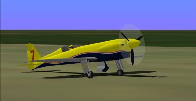
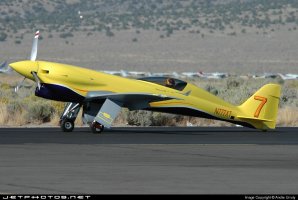
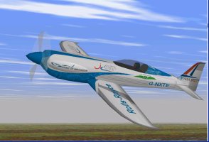
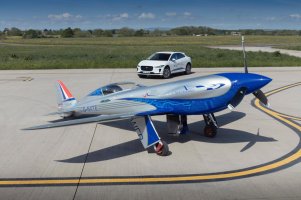
Hello Folks, (long time no see...) There is something new I was trying out, that possibly, perhaps, might be of interest for CFS1 enthusiasts: Emmulating Electro Aicraft Power in the .air file. Electric GA aircraft are most probably more interesting for FS98, but maybe CFS1 fans would fancy an electrically powered attack drone, like the RQ-20 Puma. I found a rather peculiar way to implement electro-power in CFS1 and FS98, by using a jet .air file (Eeeek! A jet!!), but with Records #401 and #404 (CLI vs AoA and CLI vs Mach) from the Cessna 182, as these wings and speeds are more fitting. Also to bear in mind for experimental purposes, would be the wings from the AF99 Balsa Glider Tutorial or from the AF99 sample Ultralight Aircraft. The most notable feature in the flight dynamics of an electric CFS1 aircraft would be that fuel is a battery stack, with no weight difference between full and empty charges. It would be included in the dry weight. In CFS1, we can achieve a very close approximation by defining a 1 USG fuel tank, keeping the difference to a minimal 6.6 lb. Depending on engine power and Battery Charge capacity( in Kilowatt-Hours), we adjust the Fuel Consumption Parameter to get specified endurance and/or range, much reducing the usual 400-440 value for jets. We can check electric current drain - i.e. pph fuel consumption - using the Lear45 EICAS gauge, as an approximate guide. With our 1-USG tank, a value of 12 pph will get us about half an hour´s endurance. Incidentally, testing for range can be made easier by increasing FS98 simulation rate. Then, to complete the emmulation, we can make a funtional instrument panel using stock FS98 gauges with modified bitmaps are for N1 and N2 Bell Helicopter engine gauges, which will be made to display Kilowatt Power and engine RPM respectively. To monitor battery charge, we use the Extra300 Acro Tank fuel gauge, which conveniently displays fuel in the tank as a percentage. It is a left tank, which we position at 0,0,0, and with a modified gauge bitmap, it shows % battery charge. The most important step is to begin by defining engine thrust. We have to convert specified horsepower to foot-pound thrust, also taking into account the higher torque of an electric motor, most noticeable in the specified rate of climb. Depending on engine size, I found the following Hp to Flb Thrust conversion factors to work very well, producing the necessary torque to maintain the rate of climb specified by the manufacturers of a couple of aircraft. Of course MTOW will also play an important role. - Medium sized engines of 400 KW - 535 hp (Rolls Royce Spirit of Innovation): Conversion factor of 3 x Hp. - Medium-small engines of 260 KW - 300 hp (Siemens-Extra 300LE): Conversion factor of 2.43 x Hp. - Small engines of 60 KW - 80 Hp (Pipistrel Alpha Electro): Conversion factor of 5 x Hp. So, with reference to military armed attack drones such as the RQ-20 Puma, I was wondering if there could be any interest for such a thing here in this forum. Cheers, Aleatorylamp. P.S. I was trying to divide this post into paragraphs, but I haven´t been successful.
 
Hello Aleatorylamp,
I believe you will run into many more issues by using a Jet AIR file rather than a regular Propeller AIR file.
The reasons are the following:
With Propeller and internal combustion engines, you have superchargers and altitude effects on power to deal with.
I believe those can be approximated as long as you are willing to accept an operational ceiling to your project.
As for Jets, you have the problems of engine power going down as well with altitude but you don't have the reduction in propulsion efficiency with less dense air AND especially a very quick reduction in efficiency with increasing speed which is normal with propellers.
Your approximation of horsepower to thrust is good only for ONE airspeed and because horsepower will go up with speed, your engine effectively gains power which something driven by propellers does not.

- Ivan.
 
Hi Ivan,

Thanks for your comments. Until Microsoft offers electric engines for its sim aircraft, what I describe above is intended as an experiment to find a convenient workaround to obtain the high torque provided by an electric axial flux motor, and also, on the way, obtain negligible weight change as the 1 USG "tank" imitating the batteries empties. Specified range/endurance is then achieved by adjusting the fuel flow parameter.

Regarding torque, the criteria to follow would be to get the rate of climb specified by the manufacturer, rather than only the maximum speed at sea level, which requires a higher multiplier than for example with turboprops.

During my experiments I saw that the higher thrust multiplier in some degree also compensates for the jet engine´s power loss with altitude, and the jet´s power/altitude curve is also smoother, apart from allowing higher altitudes than supercharged piston engines.

Incidentally, I also found there is a limitation in the sim regarding the performance of highly powerful modern racing planes with dual superchargers. I ran into difficulties with the Nemesis NXT piston engine .air file, and could only achieve correct performance using a jet engine .air file. The sim seems to be limited to the performance achieved by older technology.

Anyway, in real life electric aircraft nowadays are really still only effective for small trainers, the issue being the short range limited by battery weight. That´s why I didn´t make any more - I´m waiting to see how the industry develops before building any more!

Cheers,
Aleatorylamp
 
Hello Aleatorylamp,
There is nothing all that peculiar about the Lycoming engine in the NXT.
It is highly supercharged but only by the standards of General Aviation. It is basically a 6 cylinder 540 CID engine putting out about 350 HP at quite a bit under 40 inches Hg.
The maximum manifold pressure of this engine is actually lower than for the A6M2 Type 0 Fighter of 1940, so there should be no issues representing it with a propeller AIR file. It becomes an issue when the manifold pressure goes above about 72 inches Hg and This isn't anywhere near there. Something else must be going on.
As for high torque electric motors, just keep in mind that we normally don't have problems representing piston engines of several thousand HP and geared down a bit. You can calculate the torque of something like that pretty easily.
The problem with a jet is that no matter what the speed that you choose to use for a conversion of thrust to HP, it will be wrong for every other speed. The early jets with just a couple thousand pounds thrust were putting out the equivalent of about 80,000 HP at speed.

- Ivan.
 
Hi Ivan,
Thanks for your reply!
The problem I ran into was Nemesis NXT´s high performance compared to engine power, and I had to make a 980 flb thrust jet .air file for it, which works very nicely. I just couldn´t get the 350 Hp to provide 3000 fpm RoC and 407 mph IAS at S.L.
First, with an FS98 .air file, it was totally impossible (of course, without supercharger or editable propeller curves), and required a considerable increase in Hp (450, I seem to remember). Then I tried making a 350 Hp CFS1 supercharged piston engine, but couldn´t get the desired performance either, probably because of my own incompetence - I don´t exactly remember what the problems were. Anyway, I´ll try again, using your Riesen A6M as a basis, and see if I can pinpoint the problems so that I can describe them.
Update: The same happens as with FS98. After entering engine data and regulating power, it seems impossible to attain specified performance with the lower Hp.
Update No. 2: What a bore. I´ve been trying all morning to adapt the new .air file, only to realize now that the Riesen A6M .air file cannot be edited. It seems Windows 10 has blocked it for safety as it comes from another computer, although it is not tagged as read-only and I have changed some other properties in one of the other property windows. >Sigh< Well, I´ll have to take one of the stock aircraft and go back to square one.
Cheers,
Aleatorylamp
 

Attachments

  • Screenshot (266).jpg
    Screenshot (266).jpg
    95.2 KB · Views: 2
  • Nemesis NXT Kit #1-Dan Wright-1.jpg
    Nemesis NXT Kit #1-Dan Wright-1.jpg
    192 KB · Views: 2
Last edited:
Hi Ivan,
There seems to be something seriously wrong with my AirEd and AAM editors - they won´t overwrite CFS1 .air files when saving after changing things, and I can´t try out anything until I see what´s gone wrong.
I checked the file properties, and although the read-only box is unchecked and in the security tab the full access, modify and write options are checked, it won´t work.
This is very odd, because everything works fine for CFS2 and FS9...
Cheers,
Stephan
 
Hello Aleatorylamp,
I am sure the AIR file editors are just a temporary issue. As for editing the A6M2 AIR file, there really isn't much to be gained by doing that. It isn't even going to be close to what you are trying to accomplish. I just picked it as an example of something from long ago that ran just a bit higher boost than the Nemesis NXT. Everything in the geometry is going to be so different as to be worthless.

I believe you are having some problems with data consistency.
You are using specifications for the Kit plane NXT which has a maximum speed of about 380 or 390 MPH and using its specifications to try to reproduce performance of a RACE version of the aircraft which I saw was reaching 416 MPH. I will bet that those specifications are not the same. It is like comparing an Unlimited Class racing Mustang with a wartime P-51D. The P-51D will reach about 380 MPH down low. The Unlimited racer will reach speeds in the low 500 MPH range. I would not be surprised to find that the race versions of NXT were running 100 more horsepower.
Edit: I have to take back what I stated about 100 more HP. Lycoming only claims up to 360 HP for their engine and the kit plane is designed for 400 MPH plus.

Decide first which version you are trying to build and then find details on its engine and propeller and reduction ratio if any.
From there, you will need to calculate the Propeller Power Coefficient as you did on the P-39D-2 and see if there is some other aircraft that has a similar Power Coefficient (unlikely). If not, it is time to play with generating Propeller Graphs.
I did a lot of that and described some of the issues in the thread about my Ki-61-Id Hien. There are a fair number of examples in that thread.

- Ivan.
 
Last edited:
Hi Ivan,
I found the problem - I had installed CFS1 to the Microsoft Games directory in Program files x86, so I took it out and put it directly into "C" and now the editors work fine.

Thanks for the indications for the different Nemesis NXT versions. Mine is a 2-seater Kit version with a 345 Hp engine and a top speed of 407 mph. It did participate in some Reno Races, so I thought it would be the race version, but from what you say, "mine" must have been a lower category - not actually the higher one reaching 416 mph.

So at last, now slowly I´m starting to get some changes in the modified Mustang .air file performance, after putting in all the Nemesis airframe data, plus engine, supercharger and propeller.

I´ll let you know how it goes tomorrow.
Cheers,
Aleatorylamp
 
Hello Aleatorylamp,
If the version you have information for is the one that is reaching 407 MPH at Sea Level, it probably isn't any different from the one that reached 416 MPH.
You did not comment on propeller parameters. I did not look very hard for information in that area but other than the reduction gear, I got a pretty good feel for what is going on. Just about everything else is pretty easy to find with a good degree of confidence.

I have very good confidence in the possibilities in the CFS AIR file because in spending the time working on the one for the P-39, I found a lot of features that we were all pretty much ignoring. I barely touched on them to get the Airacobra done because I had gotten nearly what I wanted with what features I was using. I figure if you do this NXT properly, you may end up learning a lot about AIR files.
 
Hi Ivan,
OK, thanks! So it´s the racing version.
I also saw 405 mph IAS as top speed, so anywhere between 405 and 416 mph will be acceptable.
It has a Hartzel 3-bladed, 75 in. diam. constant velocity propeller without reduction gear, and as I found no reference to pitch angle range, I put in 15 to 55 deg.

I saw some engine specs of the 300 Hp version of the 6-cyl 540 CID running at 2700 RPM, so I suppose that the 350 Hp version would run at 3000 RPM.

I have found no reference regarding max manifold pressure, so I´ve put in 40 in Hg for the time being, similar to what you mentioned.

So, now I´m getting somewhere at last, and after considerably increasing propeller efficiency and engine torque curves, and lowering zero lift drag a lot, test results at 400 ft shown by the Beckwith Test Gauge, are now:
413.1 mph IAS (402.2 mph TAS), at 350 Hp and 2995 RPM, with a 38.2 prop pitch angle, which I suppose is quite a good approximation.

Cheers, and thanks again for all your useful indications!
Aleatoryplamp
 
Hello Aleatorylamp.
First of all, you need to understand the difference between Indicated Air Speed and True Air Speed.
TAS will ALWAYS be higher than IAS except at Sea Level where they will be identical. IAS is the dynamic force of the air on the aeroplane due to speed. Sometimes it is important, such as when working with climbing speeds, stalls, diving speeds, and such but most of the time, we really care about TAS.
Another thing worth observing is that there are some peculiar features in the stock P-51D AIR file. The Propeller Tables are not worth using and the CL Graph is a very very strange shape. Basically the fellow who built the AIR file for the P-51D was a Mustang fan and did his best to make the plane into a stock mod.

I did some pretty quick research into the Sharp NSX as well and the information I found doesn't quite agree with what you found. Since you are building this project, you get to decide what to use. Keep in mind that the NSX is a "kit plane" and as such, all of the components are off-the-shelf. In other words, the components such as engine and propeller are documented. I don't believe the Lycoming TIO-540 goes up to 3000 RPM. The Hartzell propeller used on this beast was listed by part number and when I did a quick search (which didn't necessarily prove anything), I found it is the same part that is typically used on a Piper Aztec. The diameter I found was also just a touch different but maybe it is just one of the options for the kit.
Since this is not my project, I didn't start a data sheet to record anything.

- Ivan.
 
Hi Ivan,
I normally use TAS for specs and test flying, but here specs were in IAS, that´s why I mentioned it that way.

A) Speed: The records of 412 mph and 415.75 mph flown by this plane are not specified as TAS or IAS.
Also, they are done in Reno at 100 or 200 ft above the ground, and Reno is at about 4500 ft above sea level... so the question remains what to aim for at S.L.

B) Engine: The Nemesis NXT has a 350 Hp Lycoming TIO-540-NXT piston engine - but it doesn´t quote RPM.
The similar IO-540-K1A5 engine delivers 300Hp at 2700 RPM at sea level, so the question remains, what RPM to go for with the TIO-540-NXT engine. I thought 3000 RPM would be good, but maybe 2800 would be more correct?

C) Airfoil: Modified NASA NLF (Natural Laminar Flow).
From your comment I am led to believe that the stock mod P51D is not useful here, so the airfoil is really not fitting, so which would be better? Perhaps the FS98 Extra 300, or Cessna 182, perhaps?

Another solution would be to use J.W Beckwith´s AirWrench 1.00 (now freeware) on a copy of the aircraft model in FS9 or CFS2, to generate the airfoil and then copy it over into the CFS1 .air file.
AirWrench generates its own CL Graph when the user enters the desired CLMax value - (between 1.2 and 1.6 normally or possibly more? Which is good for the NASA NLF?) followed by the stall speed (90 mph for Nemesis NXT). AirWrench can also generate its own engine graphs and propeller graph tables. It has the peculiarity of not using the idle RPM graph, incorporating higher values at very low RPM in the main graphs, to make sure idle power is catered for.

D) Propeller: I used 75 inches diameter, as that was ststed in the specs I was working with.

Of course, here we are going round in circles again: What information from the different sources is correct?

Wouldn´t it be good enough if we end up with a reasonable approximation to the specified performance?

Cheers,
Aleatorylamp
 
Hello Aleatorylamp,
As stated before, TAS is always higher than IAS except at sea level.
If someone is quoting a speed for record purposes, it will be in TAS.
When you get IAS values is usually in a Pilot's Manual because what a pilot sees is what is on the Air Speed Indicator (ASI) which is a reading of dynamic pressure against the pitot head. There is probably a correction table to go with it for navigation purposes.
If your numbers came from pylon racing at Reno, then work on the assumption that your actual speed will be a touch higher in a straight line and do your testing for comparison at 5,000 Feet which ought to be pretty close and repeatable for autopilot.

There are a bunch of manuals for the Lycoming TIO-540 series of engines online. I found them when I was on my phone but was unable to read a PDF with a phone. I believe the maximum RPM for all of the engines is only 2700 RPM. They probably also specify the maximum boost pressure in the manual.

Regarding the airfoil. I would suggest you take the numbers from the CL Graph from the P-51D and put them into Excel and graph them.
The curve you get may surprise you, especially after the stall. Compare them to what you get with other stock aircraft. By the way, don't use the CL Graph from the FW 190A either unless you like flying a brick.
In our simulation world, just about any reasonable CL Graph will do because we are really out to tune just two areas of the graph, one is for maximum speed and one is for maximum climb. The rest is for handling purposes and no one has brought that up yet.

Regarding propellers, I found one place that claimed to be selling Hartzell constant speed propellers suitable for the NXT, I looked up the part number that was given and found that it was apparently used quite often in the Piper Aztec. Its specifications (I believe from a FAA page) was 77 inches maximum and 76 inches minimum which isn't that different from what you found.
Have you calculated what the Propeller Power Coefficient would be for this setup?
That should give you an idea if there is a stock set of propeller tables that will be a close enough match so you don't have to actually build your own. It feels great when you get a properly working propeller, but it is usually a lot of work.
The spreadsheets I used to do basic estimates and calculations were on my Development Machine and I don't believe I had backup copies except on the Game Machine which also died.

- Ivan.
 
Hello Aleatorylamp,
I did a bit more reading on my phone earlier this evening and perhaps you should just disregard any advice I have to give you.
It appears that the Nemesis NXT flown by Jon Sharp to set all those records probably didn't have all that much similarity to the standard kit plane version of the NXT. Sounds like the kit plane with recommended equipment is good for about 390 MPH which isn't bad but who knows what the version Sharp flew could do. There was a mention of ADI use for the record runs which suggests that he was running a lot more boost than the typical TIO-540.
Your data sheet on this aeroplane must be looking pretty interesting by now.

- Ivan.
 
Back
Top