Adjusting Gotha G.I Ursinus flight dynamics for CFS2
Hello Folks,
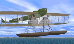
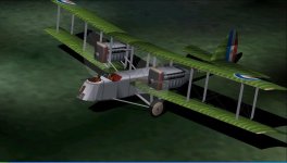
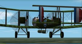
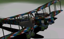
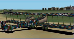
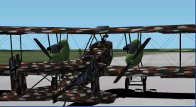
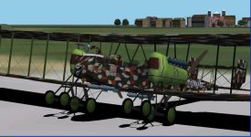
I´ve managed to get a good CFS2 .air file for the Gotha G.1 Ursinus!
Specs mention the 160 hp Mercedes D.III class 3 engine in military use, on the Gotha G.I,
as giving a maximum sea-level (500 ft) performance of:
81.25 mph with 172 Hp at 1420 RPM.
So far, I´ve managed to get the model very close:
82.3 mph, with 173 Hp at 1423 RPM.
The process is quite interesting, and I thought it was worthwhile to share on the thread.
I learnt how to do it thanks to Ivan from the CFS1 Forum, who patiently explained things I
didn´t always fully understand, how the airframe aerodynamics, the engine parameters and
the propeller parameters interact in the .air file. With time the pennies started dropping!
Then, there´s the conversion to CFS2, of course, and all the CFS1 performance has to be
adjusted again.
First I made a basic CFS1 .air file for the model to have a starting point.
Apart from the usual weights and dimensions, it needs data input for things like cylinder displacement,
compression ratio, propeller diameter and maximum. and minimum pitch angles (fixed 25-degree pitch for
the Gotha G.I). Also, convenient adjustments had to be made to the 25-degree pitch propeller graphs.
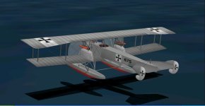
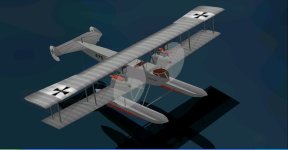
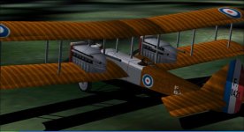
AF99 models compile directly into CFS1, and animated. Here the model file is processed first by TEX512,
to convert .xaf textures into .bmp format. This facilitates future enhanced texture repaints.
Then it is processed by the Model Patch, which makes weapons and crew visible in CFS2 when they are
added with Dp.
Ravenna and Kdriver helped me to learn how Dp fileswork.
It´s amazing what Dp lets you do, even as a beginner like me.
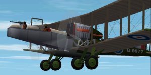
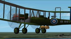
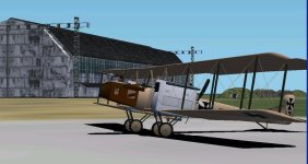
CFS2 needs a different Aircraft.cfg file, similar to the FS2002 one, but easier.
From the FS2002 Gotha G.I Aircraft.cfg written by FSAviator in november 2002, I copied the sections
needed by CFS2 into the new CFS2 Gotha G.I Aircraft.cfg.
Now comes the CFS2 tuning for the .air file, as the CFS1 .air file comes out with twice the power and
performance. This is where it gets interesting. I´m slowly getting a better at the balancing act between:
- Engine Torque and Friction Graphs.
- Propeller Efficiency and Thrust Coefficient Graph Tables,
- The three Drag entries in the Primary Aerodynamics Section,
- Wing characteristics.
ALL OF THESE affect Engine Horsepower, Engine RPM, and Aircraft Speed.
I can only do fixed-pitch propellers, or perhaps two-pitch ones, because they are easier. They only
use one of the 12 graphs in the graph table, whereas with constant speed propellers, you need to work
on quite a few more, in the range of pitch angles for a given CV prop.
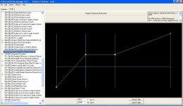
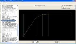
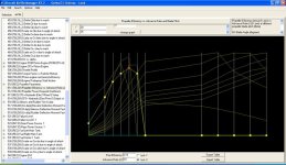
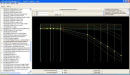
Here are some screenshots of the different graphs. The propeller graphs show, enhanced with yellow boxes,
the single 25 degree pitch angle graph used by the Gotha G.I .air file.
You can see how I was experimenting with 20 and 30 degree pitch angles as well.
My propeller graphs are different from the ones that come with stock aircraft. The shape of the downward
slope on the right is more like the real ones. It appears that otherwise you get something like perpetual motion,
and also, it is difficult to get anywhere. It also seems to be important that both graphs cross the Zero point
at the same place.
This place depends on the circular speed at which the propeller blades corkscrew through the air, known
as the "J" factor. It depends on engine RPM, propeller diameter and Aircraft speed. Each graph in the graph table
represents one pitch angle. Each column is a "J" factor, and represents an aircraft speed.
Well... for example:
Importing the Gotha G.I CFS1 .air file into CFS2, I got way over 120 mph (I didn´t bother to find out by how much), with 305 Hp at over 1500 RPM.
So....
Step 1:
-------
- Reduce the Torque graph, and perhaps increase the Friction graph. This will reduce power and slow down the
engine (and consequently also the aircraft).
- Increase Zero Lift Drag to further slow down the aircraft. Once you get more or less the Hp and Speed you
want, you will see that RPM is too low.
Step 2:
-------
- Lower the Thrust coefficient graph (only for 25 degree pitch in this case). This will reduce the power
required by the propeller, and increase the RPM. However, Horsepower and aircraft speed will also rise.
- Reduce Propeller efficiency to slow down the aircraft. This may affect RPM and Horsepower too.
- You will probably need to re-adjust Drag, depending on the result.
Note:
-----
Zero lift Drag increases slow down RPM so parasitic or induced drag adjustments may help - or even
landing gear drag in case of fixed-gear aircraft!
Note:
-----
Reducing aircraft speed also reduces RPM.
Further Steps:
--------------
Depending on the result, make further small adjustments to the Thrust Coefficient graph.
If RPM is still too low, further apply minute reductions to the 25-degree Thrust graph.
If speed gets too high, make small reductions to the Propeller efficiency graph.
Simultaneously you may need to re-adjust Drag.
And so, go round in circles until you see that you are getting closer to what you want.
Important note:
---------------
I am by no means an expert, just a hobbyist who thinks he is learning something useful.
I´m sure there are others who are much better at this than myself.
Therefore, should I have made a stupid or erroneous statement, do tell me, and I will rectify!
Acknowledgements:
-------------------
>>>> Thanks to Ivan of the CFS1 Forum for showing me this, without which I would still
be making FS98 .air files. For these, all you need is a Horsepower entry, a propeller
diameter entry, a maximum RPM entry (I think), and a Zero lift Drag entry. You can forget
about cylinder displacement, engine torque and friction, and propeller graph tables!! But, it´s
not so much fun, and if you need a supercharger or a turbocharger, you can´t have one, so there! ;-)
>>>> Thanks to Ravenna and Kdriver for helping me out with the interesting Dp files, and with
other fascinating CFS2 delicacies like TEX512 and MdlPatch!
>>>> Thanks to simmers who have had the patience to read upto here!!
Cheers,
Aleatorylamp


 Drive on.