New P3 Orion

My Apologies

Hello Aleatorylamp,

I had not been reading this thread as closely as I should have and didn't see your request until now.

Regarding Angles and Shapes:
If I understand the Wing Flexing that you mentioned, I believe it is due to the Aerodynamic Twist (Washout) between the Inner Wing and Outer Wing sections. I don't remember what it should be but it is definitely in the NASA document. I know this because when I was building templates, I was debating on including it or not but since it was so easy to add as an afterthought, I left it out to keep the templates easier to confirm.

The Wing Section looks a touch thin to me as compared to the photograph. Again, the Wing Sections are defined in the NASA document if you wish to check. The angle of the photograph is not aligned with the aircraft's axis, so that might explain some of it as well.

The Dihedral on the Horizontal Stabilizer looks like it is less than it should be. I seem to remember that it should be 8.5 degrees which is noticeably more than the wing panels.

The Merlin Powered Warhawk has been keeping me a bit busy and my old development computer is definitely acting up a bit more. If it goes, I hope I can recover my projects. I have been backing up to a flash drive periodically, but only when projects reach a nice stage of completion.

- Ivan.
 
Hello Ivan,
Don´t worry about not answering on time - I know you have your projects, and I don´t expect any regularity anyway. Whatever comes, is very welcome!

OK, I´ve taken note of your comments. I had already thought about the wing thickness, so now you mention it, I´ll take care of it. It shouldn´t be difficult, but I´ll have to check that the cracks between wings and nacelles get better instead of worse! I hadn´t checked the tailplane dihedral because the drawing looked OK, but I know it´s greater than that of the wing. I´ll fix it too.

As regards backups, I have backups all over the place! Apart from the odd CD, they are on the 2 old laptops, and on 2 old towers...

Maybe you could put the hard disk of the Pentium at 233 Mhz into the Pentium III at 866 Mhz as a slave, and safely get all your stuff out before it gets worse. But you know that...

I have a Pentium 233 MMX running at 266 Mhz, and a PIII at 800 Mhz, with as much memory as I could get my hands on. I never really use them - only as just-in-case backups for all my teaching material and my AF99 creations.

Perhaps I´m over-paranoid about that. At the end it gets kind of confusing, because some of the backups are newer than others... but anyway. The old 266MMX machine also runs a beautifull dinosaur: An 8-bit scanner with a glass bigger than than an A-4 sheet of paper, and a haloween-green light whose motor sounds lovely: A soft industrial electric hum-come-whine.

Also, this scanner is really fast and efficient at high resolution: 300 dpi (wow!!) - actuallly the only resolution that works, because the lower ones only work on 286 or 386 or maybe 486 computers. The Pentium 233 doesn´t like preview scanning either, but at least it´s the only "modern" CPU that releases the low address memory the scanner uses - if you write that into the CONFIG.SYS!!

But.... it´s fun to watch. Who´d want this old stuff anyway? I just feel sorry to throw out all this perfectly functional obsolete equipment.

OK, then, I´ll keep you posted!, and further good luck with your Merlin-powered Warhawk!
Cheers,
Aleatorylamp
 
Stabilizer dihedral

Hi Ivan,
Your help is invaluable - I will never tire from saying that.

The Orion´s stabilizer dihedral is correct now - and the worms are crawling out again!

I´d taken for granted that that was fine and after increasing the prop diameter the front view showed that the engine height seemed correct - from that point of view - but it isn´t!

The props are too low, which means now that the engines are so too.


Fortunately, however, everything is starting to click into position: As the wings are too thin, the increase in thickness has to go upwards, taking the engines with them so that the prop circle top aligns with the tailplane again.


Checking the stabilizer root-cord height, for the moment, its position on the model seems fine. Although the NASA document makes no reference to it, several photos and diagrams are consistent in that its leading-edge is lined up with the top rear corner of the cockpit side-window frame, the line being parallel with the fuselage top.


Now I´ll see if engines, propellers and a thicker wing can all line up in position.

Anyway, in theory, yet another "impossible" dilema is solved!

Update:
-------
With no datum information for either engine or horizontal stabilizer heights, a deduction exercize starting from the propeller ground-clearances yields the heights for prop-axels, engine nacelles, and then also the horizontal stabilizer, whose under-surface on the drawings is just below the inner prop-circle top.

In the NASA .pdf document ground clearance for inner props is quoted as "1 ft 9.86 in. over three point static ground line", and then it says "outer props ground clearance is 3 ft. 0.5 in. minimum".
I suppose I can take both values straight from that. Then, with the prop diameter quoted in the document as 13.5 ft, one can deduce everything else.
As George Orwell said in "1984": > Once that is given, all else follows. <


So, if my reasoning is sound, then perhaps also in practice, yet another "impossible" dilema is solved! The only doubt would perhaps be whether the inner prop ground clearance is also a minimum value, or rather a normal load value... or is this just splitting hairs?

Thanks again! (Remember, no hurry!)
BTW: Nice progress with the Warhawk!
Cheers,
Aleatorylamp
 
Last edited:
Wing stations

Well, well...

After getting the propeller size and ground clearances right, the prop-circle was still a bit below the tailplane, but both heights being correct, the only thing left to adjust were the propeller Wing Stations - consequently of course, this included everything else on the wings except the new wing tips! - i.e. engine nacelles, spinners and landing gear. Luckily these are all structures, so it´s not too much of a hassle - thank God for small mercies!

Automatically, wheel tread and prop clearances to each other and to the fuselage, suddenly all click into place as well! Now I can re-build the wings in their correct thickness, and then the whole plane should get the correct layout and proportions for all its elements.

Here we had a few days of tropical storm, and I believe Patricia is threatening Mexico as none of her predecessors have ever done before... let´s hope it doesn´t get too bad.

A nice weekend to all!
Cheers,
Aleatorylamp
 
The Wing

Hi Ivan,
I was debating how to free so many components for the engines without returning the fuselage into structures, because the latter would create hairline cracks again, and I only had 2 components to get out by making the front wheels into structures again.

Parts count would be no problem because at the moment engine structures gobble up 92 and 93 parts each - if shaped correctly! Any alteration in some places rockets it up to between 96 and 108 parts each!

Obviously an engine nacelle made of components here would most probably cost 70 or 80 parts each, so there would be enough for the wheel structures.

It had never occurred to me to have a one-component wing, as I thought it had to be split up into 3 because of bleedthrough with engine nacelles, and it seemed to work - until now that the wings are thicker.

A one-component wing would free another 4 components. Let´s see where I can scrounge the last two from! I suppose the part portruding in front of the wing would be one component, and the upper/lower bulges in the wing would be the second one. Alternatively, and because of the shape of the upper scoop, probably upper and lower nacelle components would be better, divided just under the scoop and going rear, the bottom part not reaching the trailing edge.

I´ll try it out and see what happens.

Update:
To free the two extra components the tail sting is now a structure, which is fine, and the forward fuselage from the leading edge to the cabin-rear is included with the flight deck component, freeing another component. The mid fuselage is no longer split in the middle, and now runs a few feet further forward up to a little infront of the leading edge, so that the wing-fillet components are no longer split into fore and aft wing-roots on each side, and can be glued as one piece to the central fuselage on each side.
All the wing parts - inner, mid and outer wing (except for wingtips) are now in one single component.

Presumably, and here are my doubts, any bleedthrough between upper and lower, inboard and outboard engine nacelles can be avoided...

How? - I don´t know yet: The wing being one component and the engines being four components on each side... I wonder if that won´t need a lot of glue for which there won´t be enough wing parts to apply it to?

In fact, I´ve just seen I have 10 free components! 8 for the engine nacelles and a 2 more for a possible wing-splitting necessity!

I wonder if you´d have any thoughts on this before I continue.
As before, there´s no hurry - workwise I have a rather busy week as of tomorrow.

Cheers,
Aleatorylamp
 
Last edited:
Hello Aleatorylamp,

I was just telling you about my initial approach to building a P-3 Orion if I were to do it myself.
I actually have been doing my best NOT to do any serious work beyond simple templates so I can't tell if my idea would work without actually starting a build.
Usually there are a few direction changes in the middle of a build. You saw how many changes were made during the construction of the P-38s. This project is not nearly as complicated but is a bit tougher than the typical single engine fighter.

My ideas with the Orion would be done in about this sequence:
1. Build the Fuselage as a series of Structures aft of the Bomb Bay.
2. The Forward Fuselage including Bomb Bay and Nose would be a single Component.
3. I don't know whether the Wing Fillets should be with the Fuselage or Wing Group. Including them with the Wings would make Flaps easier, but would rely on Templates which did not work with the P-38 Lightning.
4. The Fin / Rudder would be a single Component (Sorry, no Moving Parts in my design).
5. The Fin Fairing would be a Structure. No worries about Concavity there.
6. The H Stabiliser on each side would be a single Component. The Glue would be tricky here along with the Fin.
7. Each Wheel would be a Structure. If necessary, each PAIR of Wheels could be a Structure possibly with a Transparent Texture to separate them. (Wow! 6 Structures!)
8. Each Engine would be made up of a Top Component and a Bottom Component.
9. Spinners would each be one or two Structures depending on what was remaining at this point.
10. Flaps should be a series of Insignia Parts as done on the P-38 Lightning but with a duplicate of the Upper Surface in the Landing Gear Groups to prevent bleeds.
11. Propellers would be just four textured Parts each. (Wow! A Textured Propeller. Luckily we only have 4 types of Blades which means to texture it properly, the Blades need to be Up-Down and Left-Right instead of my typical X pattern.
12. Cockpit Windows would be Insignia but depending on what was left over, Fuselage Windows could be either Parts or Textures.
13. Wing Tips would be Structures with a Point at Front and a Horizontal Line at Rear.
14. All Fuselage Structures and Components would be Closed End to avoid the Sparkles that come from mismatches.
15. The Nose Component would start as a simple Structure converted to Component and re shaped as I did with the Lightning's Nacelle. In that manner, the Parts would line up pretty well.

I think this should work pretty well though of course there are things I can't see without actually starting a build myself and I don't really want to start. In order to start, I would still need some locations for the Propellers which I have a pretty good guess for.

I figure it would need to be done via a Component.
I actually just hit a bump in the road with my P-40F which I will describe in that thread.

- Ivan.
 
Hi Ivan,

Hmmm...Wow! That was a long set of useful advice by any standards! Thank you for your time and dedication!

It has now got to a point of no-return. After such a lot of work, it just has to come out decently!


Using structures for the fuselage aft of the bomb-bay will help a lot to free some more components, and I already have all the wheels as structures.

Because of the cabin shape with rather steep windshield angles, I have found on many models that a single cabin/nose component won´t work too well because the top nose surface bleeds through the cabin roof if viewed from above and behind. For this reason I always like to separate the cabin and nose components at the windshield.

Then, on 4-engined aircraft, it is very difficult to avoid bleeds if the wing is built as a single component. I have always had to split it into 3, and even then it gets very difficult to glue the animated ailerons and flaps properly. Of course eliminating animated ailerons would be of great help here.

This of course also invariably applies to a fully animated tail section.

So for this project, I may follow your way of building without animated control surfaces!
Apart from greatly reduced bleeds, it will also free some more components for the 4 engine nacelles. This will not only will be more economical on parts, but will allow better shaping too.


Let´s see what comes out. This strategy should yield better results than upto now.

I realize that a 4-engined aircraft is a little ambitious for AF99, but I think it just HAS to be possible. I mean, what USE would it be if it couldn´t make a decent, large 4-engined plane?

Thanks very much again for your indefatigable, motivating support!
Cheers,
Aleatorylamp
 
Hello Aleatorylamp,

I left out a statement in my earlier post:

I had meant to ask: How are you planning on doing the Bomb Bay?

I figure it would need to be done via a Component.

My dedication to this project is much much less than you give me credit for.
I have actually accumulated a lot of information and photographs for this aeroplane and obviously have a plan as to how to go about building one, but am not interested enough to really do it.
Even if I started on the model, it would probably never be completed.

Regarding your comments on the design:
I don't think that animated Ailerons really hurt much except for spending Parts that could be used elsewhere.
I don't have a feel yet for how tight the resources would be for building this model so I don't know what would be left over.
The animated Rudder also would not cause great issues other than for resources.
The animated Elevators I believe would cause some problems.

I don't think that AF99 was really intended for building multi engine aeroplanes to the level of detail that we are attempting. A typical FS98 model was much simpler than what we are doing today and as long as we are willing to give up on a lot of detail and some shapes, we should be able to build just about anything.

- Ivan.
 
A top and bottom half structure experiment first!

Hello Ivan,
I like your pragmatic, matter-of-fact approach!

Regarding the bomb-bay, I was leaving that to the end after fixing wings and nacelles, waiting to free enough parts and a component to fit into the cabin component bottom. I realise that an Orion with no bomb-bay would be a self defeating purpose.

The original model had a division of wing-fillet and fuselage parts at 25% MAC, wasting components. Placing that division jusy infront of the leading edge (or just behind the bomb-bay like you mentioned for the point of change to structures on the fuselage going aft) has helped to get some more resources.

I´ve re-shaped the nose component forward of the wing to make it look less like a DC-8 or DC-9 by raising the nose point. The lower edge of the windshield was already correct, and now it looks like an Orion nose.

Now, before doing the nacelles as components, I want to try out a hybrid solution first, just out of curiosity and experimentation purposes, by separating them into several structures, and fitting a component into the inner ones underneath:

A normal structure for the front with a front bulkhead going upto the bottom scoop (this saves the nook in the structure), and then two of them, top-half-only going back upto the trailing edge and a bottom-half-only structure going upto the leading edge. The bottom-half-only ones have a fore-bulkhead too for the lower scoop.

Then, the outer nacelle also gets a bottom-half-only structure for the lower rear nacelle. These structures only reduce parts count by the number of parts they have in their visible halves, and as they exist, I want to see exactly how they can fit.

Then, the inner nacelles get a component instead of a bottom-only structure, because it is box-like, for the landing gear housing.

The lower components and structures would be in wing-low right/left, and would help gluing the wheeldoors and landing gear there too. Then, the nose/wing template would be moved further aft, so as to include the forward nacelle structures.

The only problem with this is that I probably won´t leave enough parts for the bomb-bay, so I´ll have to discard the whole thing and do the nacelles as components anyway!

But I just want to see what happens!

Cheers,
Aleatorylamp
 
Interesting experiment but somewhat limited

Hi Ivan,

I suppose the convenience of using structures with their top-half-only and bottom-half-only options is not only because they are easier to make than components, but also because they allow easy placing of parts of the same structure into different groups. If no components are left over, with enough parts, in given circumstances, it can indeed be a helpful solution.

Inconveniences, as we know: a) limited selection of shapes, b) parts count, c)their notorious difficulty of adjusting vertices, but most importantly d) their vertical surfaces disappear.

For nacelles, this makes a 10-sided cross-section useless. Other cross-sections without vertical sides, would be better, but 12 sides is too many, and 8 too few.

So... so much for a game of marbles!

With my curiosity satisfied, now I shall proceed as planned with the 8 components I have managed to free for the 4 nacelles!

Cheers,
Aleatorylamp
 
Hello Aleeatorylamp,

Last night I got a bit tired and needed a break from the Warhawk and spent a couple hours doing templates and building the mid and aft Fuselage of an Orion.
I would post a screenshot but my flash drive is hiding at the moment. Lets see if I can make my own ideas work.

- Ivan.
 
Interesting Wing-Fuselage template success, but not 100%

Hello Ivan, Hello all!

I´ve just installed the thicker wing-fillet and inner-wing, and this was rather interesting:
First I tried gluing the wing-root to the body with the inner-wing in Innerwing-mid left/right, as it was before, but stangely that was only successful on the right. On the left, seen from above on the side, the fuselage bled through the whole wing-root and inner wing.

So I also put the wing-root into Innerwing-mid left/right, changing the 2 fuselage glue parts into 2 quite tall Wing-Fuselage templates, and these are doing their work surprisingly well!

From most viewing angles it´s perfect, except from below on the side, where the bottom of the opposite wing-root disappears. I´m not sure if I like this, or if this can be acceptable though, even if the main viewing angles display very well.


Another (important?) question:
I was still debating whether to give total credibility to the fuselage at 11ft 3 inches maximum diameter as quoted in the NASA .pdf document. As you are presently working on the Orion fuselage templates, I was wondering if you could just confirm if this measurement is reliable.


Cheers,
Aleatorylamp
 
Last edited:
More discrepant info and more questions...

Hello again, Ivan,

There is always something important that´s suddenly missing!
I was just checking the location of the leading and trailing edges at the wing root.

The .pdf document quotes the chord as 18.92 ft long, but then, with the way it goes on by quoting the length of MAC as 14.06 ft, with its position at 36.74 ft from the nose, and localizing 25% MAC at 40.25 ft from the nose, in addition to a 1.5 chord sweepback, and an aspect ratio of 7.5, there is no way I can understand where the root chord leading and trailing edges have to be.

Perhaps you have got that far with your templates and have got this information and could possibly clarify this puzzle?


The 3 drawings I have are discrepant: The leading edge is at 35.5, 36.4 and 37.8 ft from the nose, and the trailing edge, at 52.5, 54 and 56.8 ft.

My model has them at 36.24 and 54.7 ft, so as you can see, it is all rather disgraceful!
If I can´t get it any better, I could of course leave it as it is, as it is just in between the range of measurements, ha ha! ...and nobody would notice, but I wouldn´t really like that.

No hurry with your reply, please, and as always, I appreciate and am grateful for your comments!
Cheers,
Aleatorylamp
 
I HATE ReDoing Things!

Hello Aleatorylamp,

Funny thing about your timing....

I was just starting to have some issues with the Fuselage Width on my Templates (now Pieces) as well.
I already told you that I decided to test out the idea of whether the Templates and Ideas especially were any good by building a few pieces because I didn't want to work on the P-40F the night before last.
Over the last two nights I built pieces of the Fuselage from the Bomb Bay back to include the MAD Boom and looked at the result last night in the Simulator.

My impressions were that the Fuselage was MUCH too narrow.
Also the night before last, I found a large resolution photograph of the Orion that is very close to an exact profile view.
I don't have much faith in drawings.
I scaled the photograph to 1 Pixel == 1/2 inch, flipped it so the Nose is on the left and put a 210 Pixel margin between the Nose and the edge of the photograph.
Effectively, this gives me a reference on which the Pixel Number is twice the Fuselage Station value and helped me locate a few critical pieces.

The Photograph I used may be found here:
https://upload.wikimedia.org/wikipedia/commons/7/73/P-3C_VP-44_flying_past_Mt_Etna_c1984.JPEG

I decided to measure the diameter of the Fuselage of the Aeroplane in this Photograph in the same manner as I was using for Fuselage Stations.....

Are you ready for this????
The photograph is a bit fuzzy but my measurement shows 273 pixels from Top to Bottom of the Aft Fuselage.
At a scale of 1 pixel == 1/2 inch, we get <Drum Roll Here> 11.375 Feet. which is awfully close to 11.333 Feet as stated in the Orion drawing.....

As I stated before, the photograph is a bit fuzzy and if I had gotten 272 instead of 273 pixels, it would be EXACTLY 11 feet 4 inches. Within ONE pixel is pretty good. When measuring from a drawing or photograph it doesn't get any better which is why I prefer drawings with all the dimensions labeled.

Regarding the Wing Dimension, I know what I got from the NASA document but I will need to go look in my development computer tonight to see if I can find what you are looking for.
If you want to do it yourself, just consider that the Root Chord is at Wing Station 0 or the Aircraft Centerline.
This is pretty typical of how things are described.

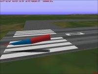
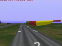
Attached are a few Screenshots, but obviously those pieces need to be reworked.

- Ivan.
 

Attachments

  • Orion1.jpg
    Orion1.jpg
    53.8 KB · Views: 0
  • Orion2.jpg
    Orion2.jpg
    39.5 KB · Views: 0
  • Orion3.jpg
    Orion3.jpg
    30.3 KB · Views: 0
Hello Ivan,
Interesting coincidence to be working on similar areas.
Pretty good going for a photo-measurement confirmation! OK, so I´ll proceed with that!
My faith in drawings dwindles more every time I look at them.
I´ll see if I find a perpendicular fly-by photo dipping a wing to see where how far the wing-root leading edge is from the nose. Maybe a video capture...
The tail art of the Mt. Etna Orion fly-past is a good one too, incidentally.
Cheers,
Aleatorylamp
 
Most of the Wing Template

Hello Aleatorylamp,

I just finished re-doing the partial Fuselage to the new dimensions using 11.33 Feet (actually 11.32 Feet because it is really +-5.66 Feet) and scaled he Fuselage Depth to be 11.70 Feet at the Bomb Bay. I would have posted a screenshot but CFS controls stopped working and I could not close out the simulator at all.

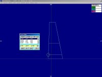
I did pull a screenshot of the important points in my Wing Template before I started getting failures.
This screenshot shows my Wing Template with the assumption that the CoG is 40.25 feet from the nose and at Water Line 150.

I set my model CoG at WL 150 because I believe it is the vertical center line of the Fuselage and at FS 588.0 very near the Mean Aerodynamic Chord.
I suspect the CoG is actually much further forward because the Bomb Bay is entirely ahead of the Wing and because the Tail Plane has a negative camber Airfoil.

I suspect the original Electra may not have had quite as fat a Fuselage as the Orion.

- Ivan.
 

Attachments

  • OrionWingTemplate.jpg
    OrionWingTemplate.jpg
    27.4 KB · Views: 0
Hello Ivan,

That´s very nice! Excellent! Thank you very much indeed!

I just couldn´t work it out, even if I did I understand what and where the mean aerodynamic chord is, but to use the 1.5 sweepback and 7.5 aspect ratio data to derive where the wing root leading edge lies was beyond my capacities.

I did some research on your hunch about the L-188 Electra having a narrower fuselage, and I found a page of a company who uses them as freighters. There was a cross-section diagramme of the hold, with a 108 inch wide pallet silhouhette sitting on the floor inside the circular fuselage.

Calculating with the pixels, the resulting fuselage diameter is 10.5 ft, exactly the same as on the original model I was deriving the Orion from. So, another mystery cleared.

OK, then, we can continue safely from here on...
Have a nice weekend!
Aleatorylamp
 
Hello Aleatorylamp,

I actually didn't know the sweep of the Wing Leading Edge.
I didn't use that in building my Template Part. It was both more and less complicated than that.

If you look at the Wing description in 2.2.2 of the NASA document, it states the Root Chord and the Tip Chord.
THAT along with the Sweep at 15% Chord tells me the layout of the general planform of the Wing.
After constructing that at 0,0,0, I modify it to add 5 degrees of Dihedral.
I then put a break in the Wing at Wing Station 65 as specified and remove Dihedral inboard.
The next step is a bit more complicated and required a bit of faith.
I located the MAC at the proper Wing Station and checked for the length to see that it was correct.
(I seem to remember it was.)
The last step was to locate it properly which is done by putting a point at 25% MAC (Insert Point twice to get 1/4)
and using Control-Mouse Click to locate it properly Horizontally and Vertically.

The other Templates were done in a pretty similar fashion except that the H Stabiliser Template still is located vertically at zero (WL 150) because I don't know the proper location.

The 1.5 degree sweep may be a reliable measurement, but my faith in the 7.5 Aspect Ratio is VERY low.
One digit of precision doesn't work well over nearly 50 feet of Wing Span.
Use the Root and Tip Chord instead. It is much more precise.

Glad the Fuselage Diameter is resolved.
You have a link to the photograph I am working from, so you can verify my estimates.
I am not sure if it is useful to you at this point, but there is also a publicly available Federal Aviation Administration Type Certificate Data Sheet for the Lockheed L-188 Electra. It may not be an exact match but gives an idea of values you may not find elsewhere.

The specific number you are looking for is 4A22 and it can be found here:
http://rgl.faa.gov/Regulatory_and_Guidance_Library/rgMakeModel.nsf/Frameset?OpenPage

On some aircraft, this document provides a wealth of information.

Hope this helps.
- Ivan.

P.S. Regarding "continue safely from here....", I would not bet on that at all.
You just haven't hit the next bump yet.
 
Hi Ivan,
Oh, dear! So I´ll just fasten my seat belt in case something else crops up!

I´m adjusting the corrected wing dimensions wings to the CoG position on my model now, so that the distance from the leading edge to the nose stays the same.

For the moment, my plan of action seems quite solid I think:

- The leading edge at the wing root is only 2.04 inches out. Even though the difference is negligible I´ll correct it because I have to re-build all the wing components anyway to make them thicker, and also the wing-root, as I have to adapt it to the 9.6-inch fatter fuselage.

- Nacelle positions are based on the prop diameter and clearances to each other, the fuselage and the ground, and their FS stations matching several photos, so these can stay where they are.
- Wing root stations have been cleared thanks to your intervention. I think my problem is that I don´t know what to do with "Sweepback of .15 chord = zero degrees". I´m applying the correct wing shape and position to my model. The dihedral is no problem, I´ve understood that, including where it starts along the wing.

- Applying the new fuselage fatness and bomb bay dimensions to the forward component should really not create any problems.

Anyway, it´s back to the workshop! There´s a lot of work to do - repeating agan and again... I hate it too.

Thank you very much for indicating the Federal Aviation Administration Type Certificate Data Sheets. That can come in handy for some models, and also many thanks for all the pieces of information you have supplied. It makes for a better designed plane!
Cheers,
Aleatorylamp.
 
Last edited:
Orion's Nose

Hello Aleatorylamp,

We just had "Halloween" here last night. I went out with my Son for Trick-or-Treat.
Not much of a candy haul though.

I think I will try to create the Orion's Nose Section by using a Structure or general outlines and tuning and then put the cuts into it for the Windows after it is converted to a Structure.
I believe this method produces a pretty good shape but is not economical at all for resources because there tend to be Polygons used in places that don't really need them.
The lines generally look good though.

This is the method I used for building the Nacelle for the P-38 Lightning and hopefully will work here as well.
It was used previously to build the Nose for the B-26 Marauder which still sits quite incomplete in the workshop.

- Ivan.
 
Back
Top