New P3 Orion

Hello Ivan,
It does not look like there are too many bleeds... but one would need a few more viewing angles to establish that.
Is it your intention to make a 3-sectioned component for the wing?
Another question I would like to ask is if it is only spinners+props in Nose left/right, or also the forward nacelle sections,these being divided by the Nose/Wing left/right Templates from whatever is in the wing.

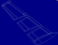
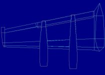
Anyway, I have applied the top outline using your very useful templates from your earllier-on e-mailed Orion to establish the correct nacelle cutouts for the wings (my nacelles were too wide from the leading edge to the exhaust), and I also applied the Wing-twist (longitudinal torsion?), as the new Nacelle side view didn´t match the slope. Now, with a positive angle of incidence inboard, the Nacelle slope towards the trailing edge coincides nicely.
I had to put lots of guide-lines along the wing reminicent of a Bricklayer´s strings to get the parts for the 3 wing components all lined up.
I didn´t put in an extra wing-part in the flat zone ahead of the ailerons and flaps because I have to save the parts for the time being, as I want (for the moment) to keep the animated surfaces.

What´s pleasing is that finally all wing-things are correctly placed! Next come the actual bodies of the nacelles.
Cheers,
Aleatorylamp
 

Attachments

  • newwing1.jpg
    newwing1.jpg
    47.5 KB · Views: 0
  • newwing2.jpg
    newwing2.jpg
    34.5 KB · Views: 0
On my model, the Engine (Forward Nacelle ahead of the Leading Edge) and everything else ahead of the Wing Leading Edge is in the Nose-Left / Nose-Right Groups. There are no Template Parts to needed to get a good separation at least not on my model.
I COULD save another four Components by putting the Engine / Forward Nacelle in with the Exhaust / Lower Fairing but I am not short of Components at the moment.

The Wing Twist is called "Washout" if it is reduced incidence toward the Tip.
Cutting apart the Wing Sections isn't hard, but it will change the Wing from 10 Parts per side to 30 Parts per side.
I hesitate to describe more detail because whatever I describe now will probably not be true in a few days.

- Ivan.
 
Hello Ivan,
Thank you for your prompt reply!

OK, the way you are dividing it as of the leading edge is also better for me.

OK with the "washout" too. I remember the effect on an R/C plane I made was incredible! The outer wing wouldn´t stall at the same time as the rest of the wing, allowing more time to correct. I´d even added triangular wing-tips like on the Britten-Norman Islander adding even more washout, further increasing the effect.

No need for any more descriptions, don´t worry.

I didn´t know a component comprising 3 separated sections was possible. I thought the texture would cover the gaps and bleed through there, but it appears not to be the case. Live and learn!
Cheers,
Aleatorylamp
 
Hello Aleatorylamp,

I am not sure what you mean about a Component comprising three sections.
I can tell you that I have lots of interlaced Components in the Cowl of my P-40s and the effect generally works pretty well.

R/C aeroplanes don't quite follow the same rules as full sized aeroplanes. You can get away with a lot more because Drag is not really much of a factor and there is a LOT of power for the weight of the airframe. I have never built a R/C aeroplane, but it is pretty obvious by the way the landing gear and generally streamlining is done. Also the typical R/C aeroplane has a pretty small propeller and I don't think I have ever seen one with a controllable pitch propeller though I am sure there are a few. Yes, it is the same air, but the Reynolds numbers are way way different, sort of like using a Bumblebee as a model for a large transport aeroplane. They are just way too different.
The reason for the elaborate discussion regarding scale aerodynamic effects is that Washout tends to have its own drawbacks as well.
With a large amount of washout, there is no AoA at which the entire wing is operating a best efficiency. The alternative method of using different airfoil sections at the root and tip is probably a much more efficient idea. The P-38 Lightning wing is a good example in my opinion.
At least this is my understanding of how things work.

I actually don't really know how my version of the Orion will turn out yet. There are just not enough resources without some changes.
I just stopped by because I had to check online for a recipe for dinner.

Now Back to Cooking!
- Ivan.
 
Hello Ivan,

Quote: >Next comes the task of cutting the Wing into several pieces on each side. It won't actually take any more Components, but will cost another 20 Parts per side.< Unquote.


This made me think that you were going to have a wing divided into 3 similar to mine but with the parts all only in one component. But whatever, it´s not important. I´ll wait and see what happens!

I understand what you say about washout and its drawbacks.
The R/C plane I built, was a high-wing "T"-Tail, like a cross between the Fokker Friendship and the DC-9.
I remember reading some basic proportion ranges and measurements for R/C models depending on what one was looking for, and I went for a stable but reasonably manoueverable design.
It had a 40-Inch wingspan, top-convex bottom-flat .air foil, with a discrete 2-degree washout, tapering to the wing-tip base to 2/3 of the 10-inch root chord. The leading edge went backwards and trailing edge went forwards.
The wingtips were triangular - pointed and sloped upward another 2 degrees at the trailing edge.
The thickness of the wing was about 1.5 inches at the root and a bit under an inch at the base of the wingtips. This was meant to make it safer before stalling, and worked surprisingly well.
There was a difference of 3 degrees angle of attack between Tailplane and Wing and the dihedral was about 2 degrees, to cater for self-stability at idle-power, hands off.
It the 2.5 cc engine was not excessively powerful for the design, as it was meant to fly, not just race through the air on a huge engine!
It really flew very well, although I never learnt to fly R/C properly. I was more interested in building just to see if it worked... typical!

Cheers,
Aleatorylamp
 
This made me think that you were going to have a wing divided into 3 similar to mine but with the parts all only in one component. But whatever, it´s not important. I´ll wait and see what happens!

Hello Aleatorylamp,

The explanation to this is actually pretty simple:

The current Wing uses the following Components:
1. Wing
2. Wing Tip
3. Inboard Nacelle Top
4. Inboard Nacelle Bottom
5. Outboard Nacelle Top
6. Outboard Nacelle Bottom

The replacement Wing would use the following Components:
1. Wing Inboard Section
2. Wing Middle Section
3. Wing Outboard Section
4. Wing Tip
5. Inboard Nacelle
6. Outboard Nacelle

It is the same number of Components with mostly the same Parts but the Top Surface of the Wing goes from 5 Parts to 5 Parts for each Section as does the Bottom Surface so it goes from 10 Parts to 30 Parts per side.

By the way, have you calculated the actual section thickness of the Wing Root and Wing Tip on your model? Perhaps your Tip actually had a Thicker section which would also have a pretty similar effect to the Washout.

- Ivan.
 
Hello Ivan,

OK, now this makes sense, of course! (...and will possibly save my day without having to give up on my beloved moving control surfaces!). With the wing in 3 separate sections, it would allow for complete nacelle bodies, like the structures I had at first - with the simplified shapes, of course...

OK, so this way around it could indeed work. Funnily enough, I have 6 components left, the two extra ones possibly being for the wheel-compartments.

With the R/C model, you´re right! The wing had a more pronounced convexity on the top surface as it went outward to the wing-tip base. I couldn´t make them thinner because they would have been too flimsy. What I didn´t know is that this also had the effect of washout. That must have added even more to the forgiving flying style. Very interesting!

OK, then. I´ll see what happens with my 4 nacelle-components then! I´ve got the shape-templates in place now have to fill them in with parts!

Cheers,
Aleatorylamp
 
Hello Ivan,
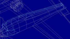
I thought I´d experiment with wires for the shape, just out of curiosity.
I made wires from the outline templates and put in some circles.
It looks a bit comic, ...if only the spaces filled themselves in automatically...
Cheers,
Aleatorylamp
 

Attachments

  • wireframeengine1.jpg
    wireframeengine1.jpg
    54.5 KB · Views: 0
Hello Aleatorylamp,

Strangely enough, that is pretty much how I do things as well though usually I have a lot more lines and sometimes only on one side as to not be too confusing.

In general though, the wireframe shows a lot in the simulator but needs to be moved around to really show the shapes.
I don't post those screenshots much because without the movement, it is much less obvious what the actual shape is.
The Bulkheads / Frames usually get retained as templates, but the longitudinal Parts get thrown away and are usually named something like Y1....Y6 or X11....X16. I have no set naming pattern for these throwaway Parts.

Looks like it is coming along nicely.

- Ivan.
 
Nacelle-fronts

Hello Ivan,
Yes it seems a practical way to see things clearly.Thanks for the additional comments to this respect!
One thing that is not working at all is the gap in the area of the upper-scoop bottom and the cowling-top behind the propeller. Initially I´d already expected that, and thought it would require extra components for the upper scoops. I wonder...

Update Actually, thinking a bit further now, the impossibility of making a one-component nacelle with a physical gap between the upper scoop and the lower cowling is not really that important, as this can be shaded in on the texture. What´s important is the actual nacelle shape, which you have shown so well as to capture the "Look". This is then not only possible, but in my case at least, there are indeed enough resources left for it! Now I´m working my way backwards along the outer nacelle, fitting in the panels, and it´s going rather well, I must say!

Cheers,
Aleatorylamp
 
Last edited:
Outer nacelle fronts and tops

Hello Ivan,

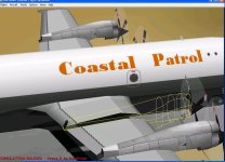
The outer nacelles are slowly getting their new shape improvement!

Although the bottom part is unfinished, I´ve textured the outer nacelles to see how the surface shows, because I´ve given them a partial concavity on the sides under the upper scoop, which can be seen from rear angles. The shading seems to work, and as soon as the lower scoop is shaped, it will pull the texture spread down to its correct position.

At the moment they only have 67 parts each - and I´m at 962 total parts (120.3%). Most of the lower part is still missing, but I think I´ll just be within the limits.


The new exhaust "opening" is now both vertical and slanted, not slanted throughout, and this is causing some problems, even with the lower flatter part inside the component, and not a coloured dark-grey insignia part. Nevertheless either of the two ways seem better than the original simplified slanted exhaust it had before.

Well, it seems to be going satisfactorily!

Update: not so much the lower scoops, though. The top ones are at the front and there´s nothing to bleed though forward of them, but these are further back and their opposite sides bleed through when viewed from forward angles... I´ll have to give them a less pronounced shape, possibly.

Cheers,
Aleatorylamp
 

Attachments

  • out-nac-1.jpg
    out-nac-1.jpg
    69.8 KB · Views: 0
  • out-nac-3.jpg
    out-nac-3.jpg
    78.3 KB · Views: 0
Last edited:
Hello Aleatorylamp,

Even though you are using fewer polygons, I don't see that there is much to choose between your Nacelles and mine.
I am of course partial to mine but that is mostly because it is my own design.
I did a bit more poking around for photographs and found that the angle on a couple of my polygons is a bit off.
I will need to correct that soon.

It is such a shame to cut up a nice looking Wing but that is what will happen soon.
The Merlin Warhawk and a couple other projects are competing for time though.

- Ivan.
 
Hi Ivan,

One´s own children are always more beautiful than others´ ...even though the grass in the neighbour´s garden is usually greener than one´s own, and tea always tastes better in someone else´s house - that´s why I think your is better too, but thanks for your good words.

Time for the Merlin Warhawk... time for everything, no problem!
Meanwhile I´ll try some things out for the lower scoop. I´ve seen the bottom nacelle surface and the scoop are flatter on the photos than what I have, so that will stop the bleeds.

Cheers,
Aleatorylamp
 
Hello Aleatorylamp,

I didn't say that my Nacelles looked nicer. I just said I liked mine better mainly because I know what went into building them.
I spent a fair amount of time taking measurements off of many photographs to get there.
Does the result show??? Maybe....

The Inboard Landing Gear Fairing is actually pretty near square on the bottom but the Outboard Fairing is not.
The nice thing about the Orion as a subject is that there are so many photographs of it that if you are looking for a particular detail, you are very likely to find it eventually in a large resolution photograph.

The Orion was getting some serious objections from my design staff. Their comments were "Why are we spending so much time on a project that doesn't meet any of our normal design criteria and that none of us have any real interest in?" The original idea was to test the idea of a single piece Wing and that idea turned out to be pretty much a complete failure already.
Some of the Paint Shop staff already departed to work on the Merlin Warhawk a long time ago.

- Ivan.
 
Hello Ivan,
I do know what you meant about your nacelles - but I think they are better shaped anyway, and exactly for the reasons you mention!

With regard to your one-piece-wing experiment, it is as good a reason as any to undertake something. I could thankfully benefit from a large part of this! Anyway, nothing is perfect in this life, and especially not in AF99, but at least the experiments are interesting, mostly leading to some sort of beneficial result.

Similar is my one-piece component idea: There is absolutely no way of achieving a bleed-free lower scoop.

I threaten my workers with putting them on chains and getting a slave driver with a whip. They might also have the syndicate dynamite the workshop and go and work for the Tu-95 people next door, why not...

Before doing all that, however, I will try what I did for the AT-9 Jeep´s lower scoop, which should give me a plausible-enough shape: A keystone-cross-sectioned bottom-only structure, glued underneath the nacelle, and with a black insignia opening in turn glued to its front.
Then, after this, the two different shapes lower-nacelle shapes that you point out should not be much of a problem to implement.

You know about the stupid bug with keystone structures, don´t you? You have to build one along the centreline, and then push it position, cloning as many as needed.

There actually used to be a pretty wide-spread BAO Flightshop/AF99 style at the turn of the century, involving a centre-line building-system and pushing everything into position afterwards.

Anyway, we shall see!
Cheers,
Aleatorylamp
 
keystone shaped Lower Scoop

Hello Ivan,

As yet things are peaceful in the workshop, but one never knows for how long! Today they are busy voting anyway...

For the moment, I´ve achieved a wonderfully bleed-less result for the lower scoop, but not so wonderful shape-wise.

It is a hybrid-built nacelle, mainly made of one component but with a bottom-only keystone cross-sectioned lower-scoop structure glued underneath. The lower-rear nacelle sides are as yet unfinished, and inner nacelles, non-existent.

Plausible enough? I wonder... For me it´s a typically unacceptable result which works well only technically and structurally, but not aesthetically.
So it´s either this or no moving control surfaces...

Cheers,
Aleatorylamp
 

Attachments

  • lowerscoop.jpg
    lowerscoop.jpg
    58.7 KB · Views: 0
Sructures Again?

Hello Aleatorylamp,

Actually I don't know about the issue with Keystone Structures. I don't believe I have ever used one on a project and probably never even used one in testing. As I see it, there really isn't that much of a point since the shape is so limited.
Regarding building on the Centerline, that is actually what I have been doing for my Nacelles since I am only building one sides Parts so as not to have to change too much when I am just reworking pieces for less resource use. It isn't my standard way of building, but this also isn't one of my standard projects either. It is really just a study of shapes and assembly techniques.

Why are you getting so complicated with a Structure Glued to the bottom of your Nacelle???
To me, this is a pretty straightforward construction since you already have your Wings in three sections:
One Component ahead of the Wing Leading Edge and one in line with the rest of the Wing pieces should work out pretty well.

My issue with my version of the Orion is that I am seriously running out of resources and also that I haven't really been doing much on it lately. Fitting and tuning the Merlin Engine has been occupying my staff lately.
Sooner or later there should be a few technicians back on the Orion project.

- Ivan.
 
Hello Ivan,

The keystone structure IS very limited... quite useless, as most structures are anyway.

For the moment I was experimenting with a whole nacelle made of a single component, and as you know with components, more or less vertical parts of portuberances similar to scoops half way down a body create bleeds through the body.

Of course, it would be quite straight forward to divide the nacelle at the lower scoop (not at the leading edge because of scoop bleed-through), and having the forward half in nose left/right will eliminate the necessity of strange solutions like glue-adding keystone structures - BTW, making the scoop structure a little smaller and adjusting the textures helped quite a lot...

Anyway, I still have to free two extra components to divide the 4 nacelles in two parts, Let´s see... I´ll have to start getting rid of all the hinges...

Cheers,
Aleatorylamp
 
Hello Aleatorylamp,

"As you know...." Actually I don't believe in what you are attributing to me.

You can use the sequence of Parts in the Component to eliminate bleeds.
I demonstrated this a few years ago with some simple Components.
The Cowl with Carburetor Scoop (Lower Front Scoop) on my A6M2 is just a single Component and there were no bleeds that I could find.
The reason it was such a pain to re do the CowlMain Component on my P-40F was because I had to do it in such a way that the concave sections would not bleed.

The Opening to the Lower Scoop can be done with a simple texture.
I can demonstrate when I have actually rebuilt my Nacelles into a Forward Component and an Aft Component.

- Ivan.
 
Merry Christmas!

Hello all!

Merry Christmas to all! I hope you have all had some nice dinners with your loved ones.
I also wish you all a Happy New Year´s Eve celebration, as well as all kinds of good things like health, love, luck and happiness for 2016.
Let´s see what we can get away with next year!!

Hello Ivan,
I thought I´d answered your last post and got a reply to it... but I don´t remember very well.
Not important anyway.
I´m still working on the nacelles. As soon as they´re finished, I´ll post the result.

Cheers,
Aleatorylamp
 
Back
Top