New P3 Orion

Hello Ivan,
Yes, I´ve just had a look into the files. Thanks a lot!
The way I was planning on using them was to move the templates over into my model to correct the measurements, after moving them into position, of course, because my CoG is at 38.7 ft from the nose and the fuselage-top at 8.5 ft, whereas on your model it´s 40.25 and 5.66.
I still have to think of the best way of going about the whole thing.

The screenshots of the old Orion: I hadn´t seen this model. In spite of its 8-sided fuselage, the plane looks pretty good for the time it was made, although the nose is a bit reminiscent of the Electra, and the thin wings which nevertheless prevent bleedthrough problems with the fuselage, I suppose.

Good luck with your computer!
Cheers,
Aleatorylamp
 
Center of Gravity

With just an observation of the aeroplane, the numbers used for you model LOOK more correct.
Imagine putting a bomb load so far ahead of the CoG. That means that there should be a major trim change when the bombs are dropped.

The NASA document states the CoG ranges are pretty close to 25% MAC.

The vertical CoG isn't stated anywhere but I believe your model's are more correct.

I picked WL 150 and FS 588 (25% MAC) because it makes for easier calculations from the documentation.
When the model is done, I will probably shift the model a bit.

Today I reshaped the Exhausts and Cowl slightly and built some reference Structures.
Once I finish the Bottom Scoops, it should be time to start building the Components.

- Ivan.
 
Hello Ivan,
OK, thanks for the comment. Then my plan of using your templates and positioning them onto my model sounds sound. I couldn´t do anything this weekend but I´ll try this week and see.
Cheers,
Aleatorylamp
 
Cowl Component

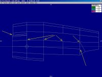
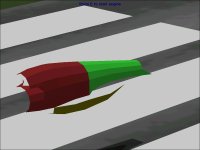
Here is a first try at a Cowl Component.

The direct copy from a Structure still requires quite a lot of tuning to actually make sense.
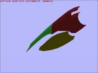
In this case, I marked out the current problem areas on the Screenshot.
Note that the Lower Scoop won't be prototyped with a Structure because it would be so far off as to not save any work.
This screenshot doesn't look bad from a side view, but is really quite a bit off when looking at how things are really shaped.

The task now is to put the divisions between the Scoops / Cowl / Exhaust and get the panel lines to flow the way I want.
Note that the Exhaust is pretty much done as well though it will still be subject to modification at a minimum to match the Cowl.
The trick here is that the Cowl will be shaped the same for inboard and outboard engines but they have to match different Lower Scoops and Exhausts....

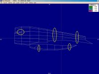
Here you can see a typical technique I use:
I create throw away Components that include as many of the current working Parts and their neighbours as possible so that I can reset the Reference pieces very quickly.

In the AFX I sent to you, just about all the pieces named X,Y, or Z-Something are of that type.
Consider those to be temporary fixtures in a workshop. They usually end up as scrap metal on the floor.

- Ivan.
 

Attachments

  • Orion-CowlComponent1.jpg
    Orion-CowlComponent1.jpg
    41.7 KB · Views: 0
Hello Ivan,
The mind boggles and I have to digest this yet. Good heavens!
But I do get the gist...
Cheers,
Aleatorylamp
 
Cowl Edits

Hello Aleatorylamp,

I am glad you understand this business. I actually have a little trouble once in a while trying to visualize what I am about to do.'
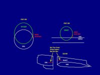
I included a little visual explanation for the folks who are following along but may be a bit too polite to ask.

The problem with Structures is that the cross-sections are regular and many Aeroplane pieces are not so regular.
If you choose to use a Structure, the widest section will always be at the vertical Mid Point.
The cross-section will have a well defined (and unchangeable) taper.

When the real Aeroplane is not shaped this way, and it seldom is, manual adjustments must be made to make the AF99 pieces match.
Note that this image is greatly simplified because there is no consideration for making the Wireframe segments line up with each other.

- Ivan.
 

Attachments

  • Orion-CowlEdits.jpg
    Orion-CowlEdits.jpg
    34.3 KB · Views: 0
Hello Ivan,

I get it. Quite fascinating! The explanation for the transition of the widest part is quite clear.
It will be curious to see how the effect comes through on the model with this very realistic looking shape.

As regards the upper scoop: Would it not be a good idea to have this separated from the propeller cowl in a different component to prevent any bleeds due to the gap under the scoop?

I only wish I had more time and energy to actually do something, but the last two weeks have been rather hectic and I have had little spare time. I haven´t even been able to play the new Starcraft 2 expansion my family gave me last Saturday, but at least once is better than none.

Anyway, I still hope to have some energy left for the wings and nacelles this weekend.
Cheers,
Aleatorylamp
 
Hey Gents,

So I was finally able to get time with my Dad over Thanksgiving dinner. I was off on his plane. It was in fact LC-81. He has pics but has to scan them in. VP-8 had LC-81 thru LC-89 at that time. He will also look for anything that he has on the P-3Bs and Cs. My Dad has Parkinsons so his memory isn't always the best. So it could take him a bit. I'll post anything I get.

'til Later,
John
 
Hello BloodHawk!
That´s very good of you. We´ll be looking forward to that!
Pity about the Parkinson´s... Both my parents had either Alzheimer or something very similar, and that was bad too. Something always starts failing, but such is life.
Cheers,
Aleatorylamp
 
Hello Blood Hawk,

Happy Thanksgiving to you and yours.
Best wishes to your Dad.

I keep forgetting that the rest of the world doesn't celebrate Thanksgiving which is why the "weekend" comment from Aleatorylamp had me confused for a few seconds. I was thinking, we already ARE on our weekend.....

I really don't know how far my version of the Orion will get, but if it gets to the painting stage, the things our paint crew would find useful are:
A serial number for the aeroplane and an exact model; The windows seem to differ a bit between models.
A nice square image of the squadron marking along with an approximate date.
Any peculiar or non standard markings. Most of my aeroplanes end up with an "Anna Honey" inscription, but that should be easy to remove if anyone is so inclined.

I presume Aleatorylamp would need something pretty similar for his paint crew.

Gotta go do some more cooking.
- Ivan.
 
Nacelle Components

Hello All,

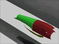
This is my first try at a (almost) complete assembly of a single outboard Nacelle.
Although I like the shape, it is unfortunately much too expensive.
What is present in the screenshots uses 118 Parts.
With 580 Parts in the model thus far, this would not leave enough Parts to build the rest of the aeroplane.

I believe I need to stay under about 80-85 Parts for what is shown here to have any chance of finishing the rest of the pieces.
This is just a guess, the actual number may end up to be significantly lower.

It is quite a pity, because I believe this shape is actually pretty good and I am about to make it much worse.
The Yellow marks indicate where I expect to reduce the Parts count.

- Ivan.
 

Attachments

  • Orion-OutboardNacelleV1.jpg
    Orion-OutboardNacelleV1.jpg
    41.2 KB · Views: 0
  • Orion-NacellePrototype1.jpg
    Orion-NacellePrototype1.jpg
    34 KB · Views: 0
  • Orion-NacellePrototype2.jpg
    Orion-NacellePrototype2.jpg
    25.6 KB · Views: 0
Hi Ivan,

Drool.... What a pity AF99 parts limit isn´t at 12,000 parts.

Must shoot off...
It´s such a busy week, and has been so, and will continue being
so for another 2 weeks or so, that "I got no time fer nutt´n".

Cheers,
Aleatorylamp.
 
Hello Aleatorylamp,

You can see my intent of two layers of polygons for the Top Scoop and Cowl. Perhaps that will not work with Parts limitations.
The problem with this assembly is that there needs to be FOUR of them, so any extra expense or savings is multiplied by four.
Hopefully the shape will not be degraded too badly and hopefully the extra complexity of the Inboard Nacelles will not affect things very much.

We shall see....
- Ivan.
 
Hello Ivan,

Interesting... So it would be 16 components for the 4 engines... At the moment I have 6 free. Even eliminating the animated ailerons, rudder and elevators on my model would only give me a total of 11.

The shape you have managed is really beautiful, and the areas you marked for simplification will be OK, and will hardly worsen the shape - perhaps also making the cross-section at the top with 5 instead of 6 parts will not be too bad. It would be flat-topped instead of pointed. Anyway, eventually, I don´t think that parts count will be much of a problem. More so, the availability of components, of course.

Without the engines, my model now has a parts count of 101.6 % i.e. 813 parts, leaving 387 for the engines and glue - 96 parts per engine. I´d also calculated between 70 or 80 initially, so 16 more is quite nice.

Well, as we always say... we shall see!
Cheers,
Aleatorylamp
 
Hello Aleatorylamp,

Actually it is only 3 Components per Engine thus far and I have more than 12 Components remaining.
Perhaps if my idea does not work, I will have to think of another assembly idea.
Keep in mind that I don't have Propellers or Spinners yet, so that is probably around 125 Parts there alone.
I also don't have Flaps or Landing Gear either.

We shall see.
- Ivan.
 
Hello Ivan,
Depending on whether a whole wing (instead of a 3-component wing) will support both engines glued to it, there would be enough components for four 3-component nacelles.
We´ll get somewhere good in the end, though, I´m sure!
I´m still bogged down with work...
Cheers,
Aleatorylamp
 
Making Things Ugly

Hello Aleatorylamp,

This morning, I made a few edits and now have the Single Nacelle down to 106 Parts.
It is very difficult to intentionally make things Uglier in a project, but that is what it will take to complete the model.

I actually have much more working room than I thought.
The Parts Count is 579 which is what drives this rework of the Nacelle pieces, but the Component Count is only 13 at the moment.
My editing process here is not logical but it comes from trying to keep this project as amusement. There are many tedious tasks ahead which would give me a better grasp on what resources actually remain, but the re-shaping of the Cowl is more fun.

Time to go cook Lunch and do some Laundry. I am a Single Parent this weekend. Anna Honey is on a business trip.

- Ivan.
 
Further Edits last night.
This Assembly is now down to 86 Parts and I suspect I can still reduce a bit further though some of the flowing lines may be affected.
Time to do the Propellers, Spinners, and Flaps to see what kind of reduction is still needed.

- Ivan.
 

Attachments

  • Orion-NacellePrototype3.jpg
    Orion-NacellePrototype3.jpg
    37.7 KB · Views: 0
  • Orion-Nacelle-86-Parts.jpg
    Orion-Nacelle-86-Parts.jpg
    30.3 KB · Views: 0
Piece of sculpture indeed!

Hello Ivan,
Sculpted very nicely, and very economical on parts indeed.
Even if for amusement only, it´s quite remarkable!
I wouldn´t reduce it any further - I don´t think it will be necessary. There are 10 extra parts per engine left over (from my parts count anyway), which may be needed for the wheelwells of the inboard nacelles. My parts count still includes extra parts for elevators, ailerons and rudder, so I think you will be well within the limit.
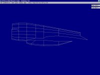
By the way, my spy liked the blueprint screenshots from the side for his Minolta!
Looks interesting how you resolved the exhaust too. I don´t suppose the inboard nacelles will be any problem, and I think I can just about squeeze out the 3 components per engine...
Cheers,
Aleatorylamp
 
Tell your Spy that this is still a Work in Progress so I would not get to hung up on exactly what is here yet.
I plan on using three Components per Nacelle, but don't follow the idea too closely until I have proven that it works.
If it doesn't, you may find that I change direction VERY fast.

I suspect that there are still going to be significant changes.
The inboard Nacelles are going to be a lot more complicated because the shapes are quite different. I wanted to do the simpler one first in this case because the forward part is the same between the two but depends heavily on the outer and just has to join the inner Nacelle.

Good Night.

- Ivan.
 
Back
Top