New P3 Orion

Hello Aleatorylamp,

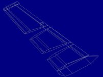
That Wing looks pretty good though it does make me wonder how you are planning to do the Fowler Flaps.
I take it from your division of the pieces that you still intend to have an animated Aileron?

Last night I started working on the Propellers and Engines as you can see from my previous post, but didn't get far because I simply had not taken enough measurements to really do anything useful. This morning I took a bunch more measurements from photographs but the problem is that I am not getting consistent numbers. Next step is to check the drawings.

Now, time to make a first attempt at Engines....

- Ivan.
 
Flap fits better now

Hello Ivan,

Well, as there are still enough parts, I was reluctant to eliminate the animated control surfaces, I´m afraid...

As for the Fowler flaps, here shown retracted, I thought they´d be invisible retracted, and then slide out with an AA animation, the pivoting point being somewhere below the wing somewhere under their leading edge. I still have to improve the shape of the wing there - it´s too thick, goes too far down, and should be flatter.

Update: I´ve just done it, and the whole trailing edge area is better now. The retracted flaps are better positioned and the shape of the coming engines will fit in better too.
The lower-aft part of the nacelles really doesn´t reach the trailing edge, and that area is better for that as well, as its´flatter.

Very good that you pointed it out!

I´ve exchanged the screenshot - showing the corrected wing, now thinner at the back.

On the nacelle structures at the moment, the lower-aft part is still bulged but that can´t really be seen very well on purpose, as it´s disguised by the darker unshaded grey on the texture.


I wonder if there is a cleaner way of putting in engines... i.e. onto a whole wing, with upper and lower nacelles glued to the single component. For the moment, I still haven´t found a way.

In my case, one of decisions to take on the engines would be how to depict the scoops. On the structures right now they are just shaded on the textures, but with the components, these should allow some shaping, I suppose. The upper component could include its own floor under the forward scoop, so that there´s a gap between the roof of the gearbox underneath just aft of the spinner - we shall see!

Cheers,
Aleatorylamp
 

Attachments

  • engines.jpg
    engines.jpg
    40.7 KB · Views: 0
  • wing-better.jpg
    wing-better.jpg
    46.6 KB · Views: 0
Last edited:
Engines

Hello Aleatorylamp,

The idea of gluing Components above and below a single piece Wing is what I have been planning all along.
Lets see how it actually works out though. I am sure there will be some bleeds, but the question is the degree.
I had originally thought it could be done with two Components per Nacelle / Engine, but now am tending toward three.

My project has used about 13 Components and 590 Parts thus far, so I may actually have the resources to make his happen.
My task right now is to get a properly shaped Engine / Exhaust / Fairing to adjust and shape to match the Wing.
Representing the proper curves is not so easy as you already know.

My Engine design is intended to show distinctive Scoop Intakes above and below unlike the single Structured version.
We shall see how things really turn out.

By the way, Check the Spinners on your model. I believe the actual Orion's Spinners have an almost two inch diameter opening in the front and do not come to a point.
One other difference between my model and yours will be that mine will have rounded Propeller Tips while yours are squared.

I will post some more screenshots when there is actually something to show. The issue is that it isn't easy to get a nice clean photograph of the inboard Engine Cowling and I am still looking for photographs to take measurements.
I suspect much of the Engine shape will be done by eyeball.

- Ivan.
 
Engine Template Structures

Hello Aleatorylamp,

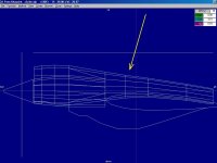
Last night, I tried to put together some basic Structures to use as reference pieces for creating the actual Components of the Engine / Intake / Fairings.

Here is how they look so far. I am not quite satisfied with the exact layout, but the shape is getting closer.
Obviously I still need the Lower Intake and Fairings.

They should fit pretty closely because they are being built around an Airfoil Template for that particular section of the Wing.
Note also that the arrow shows where there is a concave section on the real aeroplane. I don't think I have captured that aspect yet.

- Ivan.
 

Attachments

  • Orion-EngineTopScoop.jpg
    Orion-EngineTopScoop.jpg
    49.3 KB · Views: 0
Hello Ivan,
Thanks for pointing out the spinner points - I´ll fix that. I was also debating whether to round off the propellers. I think it was only the Hercules that had the square ones...

Your building methods never cease to amaze me. The shapes you are striving for are certainly very precise and true-to-life. You have all my attention!

In my case it is all much less spectacular, I´m afraid. Much simpler and far less ambitious, with fewer pieces, but still very complicated, and it´s not going very fast at all. For the moment I´ve started with the easier aft part of the outer nacelle... I have to see how it goes.

Cheers,
Aleatorylamp
 
Concavity

Hello Ivan,

The concavity you mention has had me intrigued for quite some time now. At somewhat low forward-side viewed angles it is noticeable, but seen directly from the side I get the impression that it is more of a straight line between the prominent forward curve down and the slight rear curve down, possibly acting as an optical illusion.

Then, seen from a forward-side-lower angle, there is a slightly concave kind of channel at the base of the upper scoop body where it sits on the nacelle. This channel starts at the bottom of the scoop side and leads up along the side to a kind of air intake higher up, halfway towards the rear of the nacelle.

Viewed from below, the concave channel becomes part of the horizon of the nacelle body, and there the nacelle looks like it has a concave back, whereas viewed from the side, the "backbone" of the nacelle is the horizon and looks straight.

What do you think?
Cheers,
Aleatorylamp.
 
It is concave!

Hello Ivan,
Well, it IS a little concave then, dissipating any doubts. I hadn´t seen a picture from that angle. Thanks for the photo. Anyhow, it makes the shape more interesting.
The picture also shows nice details on the exhaust I´d never seen before, although these are most probably impossible to show on the model...
Cheers,
Aleatorylamp
 
Engine Retry

Hello Aleatorylamp,

Last night, I looked over some more photographs of the Orion's Engines and decided that I should start over.
You mentioned working on the outer Engine and considering that I probably exaggerated the curves of the inboard Engine's top line AND found a less than optimal solution to the upper Intake, it made sense to start over.

The problem is that my reference photograph is one that I believe is a very well aligned side view, but because it is so well aligned, there are no useful shadows to get an idea of the contours and general shape.
Sometimes where the separation line ends is NOT where the model's lines should end because the model has to represent the underlying shape as well.

So far, I have looked at literally hundreds of photographs of the P-3 Orion and EP-3 Aries and even the Canadian Aurora. There are differences of course but some shapes are common.

It also helps to understand what the Nacelle actually contains:
(Please excuse if you already know this.)
The Engine Core itself is actually fairly small. It appears to be pretty well aligned vertically with the Wing.
The Output Shaft of the engine extends forward to a Gearbox which has the Propeller Shaft emerging MUCH higher than the Shaft from the engine.
The big Scoop on top appears to be the Engine Intake and only really goes about to the Wing Leading Edge.
The rest of the top structure on top of the Wing is Engine Exhaust Ducting and appears to follow the upper surface of the Wing fairly closely.
I am unsure of the function of the Scoop below the Engine.

These are just ideas, so be careful about adopting them.
My belief is that all of the Engine Nacelles are identical ahead of the Wing Leading Edge (with the exception of the inboard Main Gear Fairings).
The top line of the outboard Engine is very nearly straight.
If it is constructed as straight or very close, the difference in Ducting between inboard and outboard engines will take care of the noticeable dip in the inboard Ducting without exaggeration.

We shall see how this idea works out.

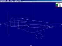
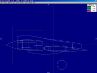
The screenshot shows the new Engine Core (which will mostly be hidden in the final construction) and the tentative line of the inboard Exhaust Ducting.
I will try to translate this to the outboard Engine.
The relationship between Engine and Wing Leading Edge should be the same between Inboard and Outboard Engines which is why the Wing Section at each location is included in the Templates.

- Ivan.
 

Attachments

  • Orion-NewCowlTemplates1.jpg
    Orion-NewCowlTemplates1.jpg
    34.8 KB · Views: 0
Hello Ivan,
Interesting, this exchange.
I also have the feeling that the outboard engine back is straighter than the inboard one.
Possibly because inner one is longer, and they were using as many aparts as they could in common, with the outer one, the dip could be caused by the resulting adaptation of a middle piece in the longer nacelle back. I´ve just seen a photo of a Hasegawa plastic model, showing a noticeable dip in the inboard engine nacelle, and only a very slight one in the outboard one.

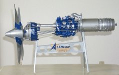
You mentioned the parts layout inside the nacelle. I had found an illustrative photo on a museum page - see below!

I was looking at more photos, and your new outline seems to be very accurate.
I also agree with your comment that as regards shapes and positions, everything except the wheel housing would be common (apart of course from the little dip mentioned above) to both nacelles.

What could the lower scoop be for? Exhaust cooling perhaps? ... to protect the wings from the heat because of the huge tanks inside them? I´ll see if I can find anything on that. And the little opening on the side? I wonder...

Cheers,
Aleatorylamp
 

Attachments

  • allison01.jpg
    allison01.jpg
    43 KB · Views: 0
Last edited:
Hello Aleatorylamp,

I always knew I had a bit of Left-Right Dyslexia, but do people also have Vertical Dyslexia?
I was reading through my post about the Nacelle contents and found I managed to reverse most of the description....
You museum image lines up pretty well with the open cowl pictures I found and my description simply does not match.... Yech!

I believe the dip in the top of the Cowl Line is because Engine is lined up vertically with the Wing Leading Edge and UPPER Surface (<-- That is the part I left out). The Exhaust Ducting comes straight back off the Engine but this 2 feet diameter Pipe needs to clear all the Wing Structure and there is more stuff to clear on the Inboard Engine.

I just label the pieces something like UpperScoop and LowerScoop, so it doesn't really matter all that much to me what they actually do....

After this project is done, it would be so simple to just fit a set of Jet Pods under a Swept Wing on each side and we would have a modern Aeroplane.....

- Ivan.
 
Unexpected distribution

Hello Ivan,

Yes, I have a bit of a vertical dyslexia thing when I´m tired - my d´s tend to become 9´s...
The description was quite understandable, and I´d seen what was in the nacelles anyway, so I didn´t find anything strange, but OK, now I do see it. The high driveshaft is higher than the propeller axel...

The picture meant to illustrate the totally unexpected distribution of the components in the nacelles, not to criticize your description. I´d imagined bigger things, and not so sparsely distributed. Amazing, how much power comes out of such a small setup. No wonder turboprops are so successful.

I´d also expected the turbine to be in the nacelle ahead of the leading edge - for heat reasons... There are designs that have that, with a very short drive-shaft. Considering the weight distribution, this must be why the Electra needed such a long forward fuselage and the Orion has the bomb-bay ahead of the wings.

From the picture one can see that the distribution follows the contour of the wing. The driveshaft is higher than the propeller, and the whole low-wing setup would be designed to make the props clear the ground, but having the hot engine on the wing leading edge, like you just said, and not inside it.

I´d actually found the picture when I was looking for an Allison Engine Logo to put on the engine nacelle texture, and was indeed surprised when I saw how the layout went.


Other setups obviously have turbines inside long nacelles ahead of a mid-wing or a high wing, with the exhausts running below the wing. High wings don´t need the long landing gears though, to get prop clearance.

It must be quite a thought process to decide how to distribute everything depending on the design, deciding on the different trade-offs.

The passenger version of the Tu-95 was so high that when it arrived in the USA once (New York, was it?) they didn´t have a ladder to get up to the cabin door for the Russian VIP´s to get out... I think they got a fire engine with the ladder to do the job.

Cheers,
Aleatorylamp.
 
Hello Aleatorylamp,

If you think Turboprops are nice and neat, you should take a look at the late model Turbo-Compound engines such as those found on the Lockheed Constellation. There is a LOT of equipment there.

I suspect the real heating problem isn't so much the Engine itself but the Exhaust Gas.

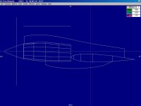
Last night, I did a bit more shaping of the Top Scoop and the Exhaust Pipes and here is what I arrived at.
The Outboard Engine's lines look pretty good to me.
The Inboard Engine still needs the Landing Gear Fairings drawn.
As you can see, there is a pretty close match here.
They both follow the Wing's Upper Surface quite closely for the last three Wing Segments.
The critical point is the station just behind the Wing LE: How it is vertically located determines the degree of concavity.

The Exhaust Opening is located 2.00 feet ahead of the Wing TE.
The height at the Opening is 1.75 feet above the Wing Surface. (I presume some of it is buried in the Wing.)
The Station ahead of that is at 1.80 or 1.85 feet up (I forget the actual number).
The next Station is at 2.00 feet up.

The remaining Station has no consistent measurement. Its height determines the degree of concavity and smoothing between the Components / Structures.

The Scoop / Fairing below ends about 4.50 feet from the Wing TE.
The Flaps are around 4 feet chord, so there needs to be a bit of room to the Wing TE.

This is what my eyeball tells me right now. I am sure things will change as soon as they are actually built.
What do they say about no plan ever surviving intact???
I don't expect this one will either.

- Ivan.
 

Attachments

  • Orion-InnerEngineTop.jpg
    Orion-InnerEngineTop.jpg
    34.7 KB · Views: 0
  • Orion-OuterEngineTop.jpg
    Orion-OuterEngineTop.jpg
    32.6 KB · Views: 0
Looking very neat!

Hello Ivan,

I found a FS98 model of a Turbo Constellation a while back - the peak of its carreer - but I never got into investigating further as to how it was done. I´ll have a look. From what you say, it sounds interesting.

I´d say your Orion nacelle´s looking as close as possible to the real thing!

Yes, it´s the exhaust gas that is in fact hotter than the engine... I hadn´t express myself well enough!


Regarding the exhaust opening, in my case I had to slant that, because I couldn´t make make AF99 do a vertical opening with the slanted sides going down on either side toward the trailing edge (or onto the short horizontal platform safeguards the TE from the hot gases).

Yours is vertical, and I´m quite intrigued as to how the slanted sides on the exhaust will turn out!

As last week, I´m very busy and have made no headway with my wing. It´s a little different from yours, the upper surface from the thickest part to the TE is flatter because that will make the nacelles easier to build. One could say my factory workers are protesting about the obsolete building technologies that I am making them use... They are observing how others do it, saying "wait and see... you´ll fall flat on your nose!". So I shall have to adjust a few things before I can continue.

Cheers,
Aleatorylamp
 
Hello Aleatorylamp,

At the moment, I am just building Templates to build Structures to build the Parts for the Components....
I don't really want to get too complicated because there will actually be four copies of each thing.
We shall see how it turns out.

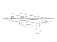
I had some time on my laptop this evening so I did some messing around in MS Paint to work out the Lower Intake and Landing Gear Fairings.
The Lower Intake got a slight redesign to match up better with photographs.

After all that is done, we shall see if my assembly idea actually works or not.
Keep in mind that what looks good on a 2D screenshot may not work out so well in 3D.
Then again, some things may end up being simplified because the differences are not very visible but cost scarce resources.

- Ivan.
 

Attachments

  • Orion-GearFairing1.jpg
    Orion-GearFairing1.jpg
    26.2 KB · Views: 0
Hello Ivan,
What I´m going to do at the weekend is total and blatant industrial espionage:
I´m going to copy your plans and adapt my wing and nacelle to the contours.
My workers think they will suspend the strike if our spy comes back with clear enough Minolta photos...
Actually the spy is old-fashioned too... He can´t even hack computers!
Cheers,
Aleatorylamp
P.S. He got back with all the wing and nacelle pictures, and has just come out of the dark-room. Everyone here´s busy with them now...
 
Last edited:
Constellation Turboprop and Turbocompound

Hello Ivan,

I just had a look, and illustrated myself. The Turboprop Constellation I knew about is a totally different kettle of fish from the Turbo Compound.

I had heard of the latter, and never really understood how it worked. I thought it was some kind of turbo supercharger, but it actually works quite differently.

It seems like mixing a radial engine and a turboprop to the same propeller, the turboprop part feeding on the unburnt fuel in the radial engine´s exhaust gases. A bit confusing to follow, but I think I understood how it actually works. The number of elements on such an engine could give a mechanic claustrophobia!

From a technical point of view, it´s rather overdoing it a bit, but OK, they got a considerably high amount of extra power with no extra fuel consumption.

I suppose that after they saw what the Turbo part of the Compound could actually do, they caught onto the idea of taking away our beloved pistons (the more there are, the more we like them), and just using the mechanically cleaner and simpler turbine... which we all turn our noses down on in disgust.... ha ha! ...I wonder why we do that - maybe it´s the sound... a deep throated rumble and roar is more impressive than a high-pitched whine or shriek, I suppose. Compare a lion or tiger to a parrot...

Cheers,
Aleatorylamp
 
Hello Aleatorylamp,

Tell your Spy to come back to my workshop this evening.
We will send a full set of Blueprints, Jigs and Templates home with him.

I will email you a full set of Templates and Files to build my version of the Orion.
Do be careful though: Any file with the name beginning with X is a temporary working file.
When I need to create a disposable reference Part, I usually call it X1.afp or X2 or something like that.
Note that I didn't say "the AFX" because there are actually three AFA assemblies or is it four now?
....So I will actually ZIP the contents of my Project Directory to send to you.

My understanding of a Turbo Compound is a little different:
On a TurboProp, fuel is used to power the Turbine which is geared to the Propeller.
On a TurboCompound, fuel is only used on the actual Piston Engine.
I don't think the unburnt fuel in the exhaust gasses is intentional though I may be wrong.
The Exhaust Gasses are use to drive a Turbine which is geared to augment the power provided by the Piston Engine....

I thought you might be interested in how complicated things got at the end of the Piston Engine era.
That Wright R-3350 actually got to be a pretty reliable engine by that time.
(The earlier versions on the B-29 were prone to catching fire even without enemy action!)

- Ivan.
 
Hello Ivan,

Instead of industrial espionage this is more like international cooperation!
Instead of the spy I will send the courier, although I fear it´s the same person doubling up to save on salaries...

I´m very honoured indeed at your gesture and appreciate your efforts very much.
It will no doubt make things easier. I have already printed out the diagrammes you posted, and was planning the modifications, which will not be that difficult, but your templates will undoubtedly facilitate the job!

Regarding the turbo compound, the descriptions I read apparently show both possibilities, if I understood correctly. One like you say where there´s a compressor using the expanding exhaust gases to transfer some extra power to the propeller shaft, and another, with cold air mixing in and an extra ignition to use the unburnt fuel in the exhaust, and that really put some extra power into the propeller shaft.

This way they got the Connie some extra 550 Hp for take-off and 275 or so for cruising. It didn´t extend the range, but increased the power for the lengthened version that allowed the 23 extra passengers that the improved version of the Douglas DC-6 was offering.
Fascinating, how engines developed! There seems to have been fierce competition going on.

Cheers,
Aleatorylamp
 
Hello Aleatorylamp,

Please check your email and let me know if you can access what I sent.

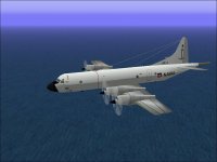
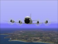
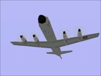
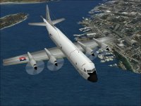
I was poking around a little while ago and found this rather interesting but OLD aeroplane.
The flight model isn't very good, but the sound is about what I would expect from the real thing.
What do you think?

It definitely isn't mine because I haven't gotten anywhere near this far yet.

- Ivan.
 

Attachments

  • OldOrion1.jpg
    OldOrion1.jpg
    50.9 KB · Views: 0
  • OldOrion2.jpg
    OldOrion2.jpg
    47.3 KB · Views: 0
  • OldOrion3.jpg
    OldOrion3.jpg
    25.1 KB · Views: 0
  • OldOrion4.jpg
    OldOrion4.jpg
    86 KB · Views: 0
Back
Top