Project Martin A-30 Baltimore

Baltimore Mk.IIIA - Mk.IV

Hello Ivan,
As you will imagine, I would again need your opinion... I hope it isn´t too bothersome!

First, a little background:
The difference bewteen the Baltimore MkIIIA and MkIV was basically that the MkIIIA had twin 0.5 caliber guns in the dorsal
turret, and the MkIV had twin or double-twin 0.3 caliber guns there. The twin 0.5 caliber guns were then also adopted for the MkV, as they had greater punch. Then, both planes had the 1660 Hp R-2600-19 engine, which was, as you said, less powerful than the -13 or -29 on the MkV. However, compared to the 1600 Hp GR-2600-A4B on the MkI/II predecessors, it had 60 Hp more at S.L., although at 10000 ft, it was 40 Hp under.

Now for the .air file:
Aims: (no more data to be had!)
a) S.L.: 1660 Hp
b) 11500 ft: 1275Hp and 305 mph
c) Ceiling: 23250 ft.

In order to achieve specified performance it was necessary to drastically reduce Boost Gain to 1.7358 compared to the 2.125 in the .air file of the 1700 Hp R-2600-13/29 engine, but with similar friction and torque graphs, as S.L. performance was only 40 Hp under.

This exactly allowed the 3 specified conditions to be kept, but came with strange side-effects:
Engine critical altitude went far down to 5000 ft, with a high 313.7 mph speed peak here as well, and WEP/non-WEP difference is only 0.2 Hg. Quite soon after, there is no difference at all. However, this is no problem, as WEP is to be used only for take-off anyway.

So, here is the power curve for the Baltimore MkIIIA. The necessarily low Boost Gain entry has caused quite a pronounced low-altitude bulge which peaks at 8.7 mph faster than the specified 305 mph max. speed, although it could be appealing to simmers, I suppose!

____S.L.: 44.0 Hg, 1660 Hp, 301.2 mph (Power exact as per spec.)
__500 ft: 44.0 Hg, 1665 Hp, 302.1 mph (Non-WEP: 42.0 Hg, 1568 Hp)
_4500 ft: 42.0 Hg, 1628 Hp, 311.1 mph
_5000 ft: 42.0 Hg, 1637 Hp, 313.7 mph (speed peak here. - Here WEP is only: 42.2 Hg, 1644 Hp !!)
_5500 ft: 41.4 Hg, 1616 Hp, 313.2 mph
_6700 ft: 39.6 Hg, 1544 Hp, 312.1 mph
_8000 ft: 37.7 Hg, 1472 Hp, 310.1 mph
10000 ft: 34.9 Hg, 1359 hp, 307.9 mph
11500 ft: 32.8 Hg, 1275 Hp, 305.0 mph (Speed and power exact as per spec.)
12500 ft: 31.5 Hg, 1221 Hp, 303.6 mph
15000 ft: 28.6 Hg, 1102 Hp, 299.7 mph
23000 ft: 20.4 Hg, _754 Hp, 273.2 mph

Ceiling 23250 ft: RoC 100 fpm, 262,5 mph TAS, 184 mph IAS.
Your latest posts in the Warhawk thread came in very handy!


I wonder what your verdict on such a large low-altitude bulge could be!
Thanks very much in advance,
Cheers,
Aleatorylamp
 
Hello Aleatorylamp,

My cell phone is very low on battery, so I hope I can finish this post before it dies.

I believe the problem here is that your SL power is way too high.
Remember this is a best fit kind of thing; You will never get an exact match in all the places you need.
The idea here is to get a good match in as many places as possible.
Generally this means that your SL power and Critical Altitude power will be a bit low so that the medium altitudes are not too high.

In this case, your Supercharger Boost Gain is probably too low: The Critical Altitude is too low.
The problem is that your target power for SL is a bit too high.
My guess is that while you are trying to match the Take-Off power, the normal non-WEP maximum is too high.
Because of the unavoidable middle altitude highs, I believe is usually a good idea to have both SL and Critical Altitude power a bit low.

That is my belief but I am also not able to experiment with the AIR file, so I can't tell you any more than I have already covered in prior posts.

BTW, The test data for the Warhawk in real life does not seem to be all that good of a match to what I am getting.
Then again, the test data isn't really for exactly the same aeroplane that I am trying to simulate.
The actual speed for best climb rate is more like 160 MPH rather than 180 MPH.
The engine settings are also not necessarily the same. I am testing at full power and the climb setting is not that high.

-Ivan.
 
The best fit

Hello Ivan,
Thank you very much for your explanations and argumentation. I hope things are going well!

I understand what you mean and how to go about it more effectively now. It also illustrates the way you set up your Mitchell-C´s engine parameters. With your indications I had got it quite well for the Mk.V, as you have seen from the last report on its power curve.

Now I can also correct the strange results I got after correcting the Mk.IIIA/IV ceiling performance with the necessary power reduction higher up.

Thanks very much again!
Cheers,
Aleatorylamp.
 
Adjustment Margin Criteria

Hello again!

Following the reasoning, in order to get the best fit thing fitting the best, I suppose some margins have to be established in order to get enough play so that slowly things start matching - concepts being:

- SL power, set by torque graph
- Engine critical altitude set by Boost Gain entry (where WEP/Non-WEP is the same)
- Specified Power at aircraft critical altitude set by both Torque Graph and Boost Gain
- Ceiling power set by both Torque Graph and Boost Gain

Suppositions for this model:
1) Specified power of 1275 Hp at 11500 ft perhaps indicates an engine critical altitude of around 9000 ft (+-500 ft), defined by a corresponding Boost Gain setting. If higher than 2.125 or so, power at ceiling is too high... If lower than 2.0, engine critical altitude becomes insufficient. I liked 2.05, but still got too much power at ceiling.
2) Ceiling of 23250 ft implies a max. RoC of 100 ft/min, so 790-805 Hp is needed here for this model.
3) Rated Max. SL Take-off power of 1660 Hp must be lowered. But by how much? Even 1600 is still too high...
The R-2600-19 was less powerful than the R-2600-13 on your Mitchell-C, where you had 1618 Hp at SL, so I have the feeling that I should be going for maybe 1580 Hp or so.

For a start, some Boost Gain/Torque combinations to achieve approximations on the first 2 suppositions give me a max. 44 Hg Power at SL of only 1385 or 1412 Hp... Too low. I still have to start playing with Drag to get the Power numbers up a bit.

Obviously all this has to be made to fit somehow, even if we need a wedge and a hammer!

The question is, how low can a fitting adjustment go as far as SL power is concerned? ...and at the same time approximately retain some relation to specifications.

Cheers,
Aleatorylamp
 
Almost in Agreement

Hello Aleatorylamp,

We just got back from a drive down to the University of Virginia to pick up my daughter.

Regarding your summary:

1. Sea Level power set by Torque / Friction Balance. Note this is NOT WEP / Take-Off Power you are setting here
If you have a choice of getting WEP correct or Normal Maximum correct, get the Normal Maximum correct.
It has greater effect.

2. Engine Critical Altitude set by Supercharger Boost Gain.
If you get it slightly lower, it is fine because if the Manifold Pressure is the same, the HP will be slightly high at Critical Altitude as versus Sea Level.
Ignore WEP in this case because for this engine it should have NO EFFECT at this altitude.

3. Engine Power at Critical Altitude is set ONLY by Supercharger Boost Gain.
If you use Torque / Friction, you will affect Sea Level power and are back at Step 1.
You are calling it Step 3, but it is the same as Step 2.

4. Ceiling is set by balancing Torque and Friction to get the SAME Sea Level power as Step 1.
This will affect power above Critical Altitude but will not make a significant difference below Critical Altitude.

Regarding your suppositions for this model, I would not worry too much about an exact match for Sea Level Take-Off Power.
Get the Normal Maximum correct to match the rest of the graph because it will have much more influence on everything else.
I can't discuss exact numbers for your model because I can't see what you are balancing.
I chose to run higher power at Critical Altitude for the Mitchell because I believe that the performance is the important part and the exact Horse Power is a bit less important.
You get to make the choices about what is important if you can't get everything to match.

Hope this makes sense.

- Ivan.
 
Hello Ivan,
I hope the university year went well for your daughter. The drives to leave mine in the mornings are about 7 minutes... and they come back by tram in the afternoon... Here on the island distances are often short...

Once more, thank you for the additional details and balancing criteria suggestions and corrections! Very nice!
I´ll try some more things out and see how it goes.
Cheers,
Aleatorylamp
 
Hello Aleatorylamp,

My daughter just went to a rowing camp for a few days. She will be a senior in high school next year.

No university yet.

- Ivan.
 
Hello Ivan,
I thought I´d got something wrong there... Anyway, rowing and camps are nice, so both together is even better! I´m sure she enjoyed it.

I´m doing the balancing act on the Mk.IIIA now. Thanks for the clarification on preferably using the non-WEP S.L. power as a guide-line. If the R-2600-13/29 gave 1700/1500 WEP/non-WEP Horsepower at S.L., then presumably its R-2600-19 not-so-powerful predecessor rated at 1660 WEP Hp would possibly have given about 1470 Hp non-WEP. At the moment I´m at 1450 Hp, so I seem to be quite near, and I am trying a Boost Gain increase to get critical altitude a little higher.

I adjusted the Ceiling following your tutorial and got it more or less around 800 Hp there, which gives a RoC of about 100 fpm, which should be OK, but as you say, it may get a little higher after increasing Boost Gain, so I won´t worry too much about that, the importance lying in the elimination of the low altitude bulge in the curve.

It´s interesting to see how different the adjustments for the older -19 are turning out, compared to the improved -13/29. It must have had a completely different blower - and perhaps slower cams?

Cheers,
Aleatorylamp
 
Hello Ivan
After all this time asking you questions and receiving your patient replies, I´ve begun to see how the engine parameters interact. It needed time for the things that you said over and over again in different ways to make sense and to fit into the whole picture, and also for the reasoning behind your recommendations to become clear.

I´ve been experimenting with the already quite acceptable Mk.V .air file from a few weeks ago, trying to marginally improve it. I tried out different friction/torque variations (same S.L. power), and also Boost Gain settings, to see their effects on performance at Critical Altitude and Ceiling.

The effects of all this are of course visible, but perhaps not entirely obvious, although one does see that certain possibilities of maneuvering are granted, especially as regards your recommendation for reducing S.L. power to get more correct readings below critical altitude!

Also, I was going to ask upto what extent one can increase friction/torque, but it is now quite obvious how altitude performance starts waning if the increase is too strong!

What is definitely remarkable, is the degree to which the workings of .air file parameters have been decyphered by different people over the years, while on the other hand, it is completely obscure why CFS was made to handle these parameters the way it does in the first place.

Anyway, your patience is commendable!
Cheers,
Aleatorylamp
 
Hello Aleatorylamp,

I am glad you understand what I have been trying to tell you.
I don't know that everything I tell you is correct, but it is what I currently believe to be true AND
it seems to work in a predictable enough fashion.
Hopefully somewhere along the way, some of what I have been doing actually qualifies as a new discovery rather than just a simple refinement of what was already known.

I don't know how good my patience actually was. At times, I wasn't very patient at all.

Regarding the less than optimal way Superchargers are handled in CFS, just remember that before CFS, there was FS98 which didn't handle Superchargers at all. Think about how you would build the Baltimore's AIR file for FS98 and perhaps then you would appreciate CFS a bit more.

Looking back at Flight Simulators, I think I would have been much more satisfied if I had started building for CFS2 instead of CFS.
It is a much more full featured simulator for WW2 era aeroplanes.
Then again, with CFS2, there would not have been the drive to prove that a nice looking model with minimal bleeds could actually be built.

- Ivan.
 
Hello Ivan,
Oh, but I do very much appreciate CFS, especially because of AF99 - otherwise I wouldn´t use it or build for it - even if I do get frustrated from time to time. I could also build for FS2002, without so many the bleedthrough problems, but lacking the game-feature, there is less motivation, even though the .air file does include superchargers...

Of course, with FS98´s simpler engine parameters, sophistications like superchargers could perhaps at most be emmulated to a limited extent by adapting a jet engine .air file (with prop sounds). This would require eyeballing the mandatory Hp-to-flb thrust conversion, and one would end up with a power curve that compensated power loss with altitude - upon which one would have no control.

Just like the drive to prove that AF99 can make a nice looking model for CFS, we have the drive to prove that a reasonably accurate supercharger can be made for CFS!

An interesting thing would perhaps be to alter the .AirEd info/help files with the new data you have found out, and publish it somewhere...

Cheers,
Aleatorylamp
 
Hello Ivan,
In view of my (or our) achieved success in my understanding CFS supercharger intricacies, I have managed to come up with the following results for the lower powered engines of the Baltimore Mk.IIIA/IV, which apparently gave a maximum of 1660 Hp at S.L., and 305 mph max. speed with 1275 Hp at 11500 ft.

Test: 100% fuel, 0% bombs, 100% ammo

__500 ft: 44.0 Hg 1571 Hp, 286.0 mph >>>> Optimal estimated WEP Speed: 289 mph
__500 ft: 42.0 Hg 1475 Hp, 280.1 mph >>>> Non-WEP Hp/mph base setting
_4500 ft: 44.0 Hg 1632 Hp, 299.0 mph >>>> Allow WEP for intitial climb perhaps?
_4500 ft: 42.0 Hg 1533 Hp, 294.1 mph
_6700 ft: 42.0 Hg 1567 Hp, 300.6 mph
_8000 ft: 42.0 Hg 1587 Hp, 305.5 mph
_8500 ft: 42.0 Hg 1594 Hp, 307.7 mph
_9000 ft: 41.8 Hg 1595 Hp, 309.4 mph >>>> Speed peak here
_9500 ft: 41.0 Hg 1560 Hp, 308.9 mph
10000 ft: 40.2 Hg 1525 Hp, 307.3 mph
10500 ft: 39.4 Hg 1491 Hp, 306.7 mph
11500 ft: 37.9 Hg 1429 Hp, 304.4 mph >>>> just under specified 305 mph
12500 ft: 36.4 Hg 1364 Hp, 302.3 mph
15000 ft: 32.9 Hg 1216 Hp, 297.4 mph

Ceiling:
23250 ft: 23.3 Hg _791 Hp, 267.2 mph
RoC: 92 fpm, 263.3 mph TAS / 184.6 mph IAS

Well, I just thought I´d ask you what you thought of these results.
I have tried to fir the curve as best as possible, using 2.0 Boost Gain so that critical altitude wasn´t too low.
I wonder...

Thanks in advance for your time and answer! Remember... No hurry at all!
Cheers,
Aleatorylamp
 
Spanner in the works!

Hello Ivan,
I had come accross the following technical details in the .pdf I mentioned a while back, and didn´t notice some rather obvious performance details (typical...). The hydra should bite my head off.

(The "MkIV" must refer to the aircraft, not the engines).

Engines: 2x1660 hp Wright R2600-19 Cyclones MkIV - 14 cylinders (2 banks of 7)
Revs:
Taxiing - 1000 rpm
Take-off - 2400 rpm
Normal Cruise - 1850 rpm
Economical Cruise - 1750 rpm
Speeds:
Stall - 95 mph
Approach - 110 mph
Cruise - 220 mph

The given RPM indications show the lower power output of this engine, a design prior to the improved -13 and -29 series.
This, together with the article you pointed out on the initial R-2600 problems, ties in with your idea of limiting maximum power output.

The 1000 revs for taxiing ties in with the fact that prolonged idling below 1000 rpm fouled up spark plugs.
Take-Off power is at 2400 RPM instead of 2600
Normal Cruise is at 1850 RPM instead of 2400
Economical cruise is 1750 rpm instead of 2100

Stall would be clean stall, as landing speed is quoted elsewhere as 87 mph, and must have been with flaps.

I suppose this really puts a spanner in the works for the -19 engine, as I´ll have to lower RPM significantly, although the power curve should stay the same with a lower RPM setting and corresponding adjustments in the torque graph.
Never a dull moment...

Update:
I´ve just done it: Increasing the torque graph, RPM are down to 2400, and HP is the same throughout the curve, but I´m 3 mph slower at 500 ft, 0.6 mph faster at the 9000 ft peak, and 2 mph faster at 11500 critical altitude. Not really distressing, and probably quite forseeable I suppose, as the slower revs with the same power react differently to the changing air density.

If instead of increasing the torque graph, the friction graph is reduced, Hp falls a bit, so speed increases at altitude are a little lower, but speed loss at 500 ft is a little higher, so even with Drag compesation we end up the same as before.
Sixpence of one, and half a shilling of the other...

Cheers,
Aleatorylamp
 
Last edited:
Hello Aleatorylamp,

I was just about to tell you that your numbers for the Mk.III / Mk.IV look pretty good.

If I were in your position right now, I would first reset the RPM limit to 2400 and then do a quick power test at the three points:
Sea Level,
Maximum Speed Altitude (Note I did not write Critical Altitude),
and Service Ceiling
to see which direction things needed to be adjusted.

My initial guess would be that you tend toward the Torque values you had for the Mk.V though the real choice depends on whether your how low your Service Ceiling power has become.
In other words, my guess would be to increase the Torque values to match the Mk.V. If you find that your power at the service ceiling is too low, then you might have to reduce the Friction instead.

If you are getting power output at about the correct values, then you MIGHT want to adjust Propeller Efficiency in Table 511 so that the values at the advance ratios at Maximum RPM at Sea Level are slightly increased.
To me, this is a last resort because if you do it badly, then performance starts to get very confusing.
It will almost certainly change your climb rate as well.

- Ivan.
 
Hello Ivan,
First of all, thanks for the positive reinforcement on the numbers that look pretty good! At least the basic shape of the curve is there.

Another good thing is that at least there seems to be some tangible information available on the obscure R-2600-19 engine.
I was thinking whether one could interpret the 1660 Hp as being a factory maximum with 2600 rpm that was never used in practice because of engine damage, so a 2400 rpm maximum was standard, and possibly therefore not with 44 Hg either, only 42 Hg. Would you think that was a more or less accurate guess?

After the RPM thing, with 2400 now, I thought the Torque adjustment behaved better as SL speed didn´t go down so much and the speed increases at altitude were only slight, where in fact, they were still within the 5-6 mph range over specified speed that we had discussed as acceptable a while back.

I was trying to avoid working on the propeller efficiency values... Instead, I thought of asking you whether to try changing the maximum and minimum pitch settings in Prop Parameters 510.

Here´s the new test result for the 2400 RPM corrections.
It looks much better than I´d initially feared, and you are quite right about the Torque Graph being very similar to that of the Mk.V - and for the moment I´ve left Friction unchanged.


__500 ft: 44.0 Hg 1571 Hp, 283.0 mph >>> Optimal WEP Speed: 289 mph
_9000 ft: 41.8 Hg 1595 Hp, 310.2 mph >>> Speed peak here
11500 ft: 37.9 Hg 1429 Hp, 306.4 mph >>> Just over specified 305 mph (this just by the by)

Ceiling: This is MUCH better than expected!!
23250 ft: Level flight: 23.3 Hg _821 Hp, 267.5 mph TAS 187.5 mph IAS
RoC: 818 Hp, 103 fpm, 258.9 mph TAS / 180.9 mph IAS

Possibly it looks like one should leave it this way, wouldn´t you think?

Cheers,
Aleatorylamp
 
Last edited:
Hello Aleatorylamp,

I have a silly and possibly deadly question for you:

Why do you think the manifold pressure settings are the same from the R-2600-13 to the R-2600-19 engines?

- Ivan.
 
Hello Ivan,
A silly and deadly question... Oh dear! But I still don´t get it.

There is no manifold pressure data available in the .pdf on the African Baltimores, so, what Hp came out of the 2400 rpm, and with what MP? Quite frankly, I haven´t a clue, and I can only speculate.

In the .air file, the MP settings are the same because of the data inherited from the -13 engine - the same blower used the same way for both engines with the same cylinder capacity and aspiration volume.

In this case it is just a matter of the engine not giving 2400 rpm and hence not 1660 Hp to avoid damage, but OK, then MP stayed at 44 Hg for take-off the same as for the other engine.


The engines were basically the same, but improved over the years. How? Perhaps compression, minor changes to cylinder capacity, cam-angles, and perhaps blower efficiency? I really don´t know. The -19 was in turn better than the 1600 Hp GR-2600-A5B predecessor. Did that other one have still lower RPM? Was the blower even more primitive, or was it the same? Could it handle 44 Hg too?

Cheers,
Aleatorylamp
 
Baltimore Tail

Hello all, hello Smilo, hello Ivan!
So we are building again, after the .air file success (Thanks, Ivan!).
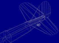
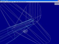
Now the tail section components and structures are ready, including the tailwheel and its struts.

Horizontal stabilizers are components, glued to the aft-fuselage component with Ivan´s Conga (!). The aft-fuselage top is rounder at the top than at the bottom, as per Smilo´s Plan. This can be seen from the joint to the mid-fuselage which is still a crude oval-cross-sectioned template structure.

Fin/rudder is in two structures: The top one with triangle-bulkheads is in Tail-Upper (this seemed to be cleaner than glued to the aft-fuselage in Tail, where tailplanes bled through the fin/rudder momentarily, most probably because it is so long and reaches beyond the fuselage end), and then, the bottom rudder structure with vee-bulkheads, is in Tail.

The lower rear part of the aft fuselage component shape matches the Vee of the lower rudder structure.

Bleedwise it is very clean (no moving parts for the time being, as I´m quite envious of Ivan´s clean building-style!), except for the fact that viewed from below, the tail-wheel and its struts sometimes get rubbed out by the aft-fuselage, but I fear it is unavoidable.

More later or tomorrow!
Cheers,
Aleatorylamp
 

Attachments

  • Balt-tail2.jpg
    Balt-tail2.jpg
    37 KB · Views: 0
  • Balt-tail3.jpg
    Balt-tail3.jpg
    71.5 KB · Views: 0
Better shape

Hello again!
I found a better shape for the lower rudder structure, matching the aft fuselage component, i.e. the keystone bulkhead.
This way, although the difference is not really too noticeable, it is planwise more correct. (Using 2 structures for the upper and lower fin/rudder will save components that will be needed elsewhere in the future).
Here´s a postcard with Tower Bridge... and blueprint screenshot.
Cheers,
Aleatorylamp
 

Attachments

  • Balt-tail5.jpg
    Balt-tail5.jpg
    86 KB · Views: 0
Fuselage done

Hello!
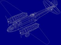
Now the fuselage is done - in components, including a basic try for turret, guns (sructures here), cabin and forward glazed nose.
The Baltimore is making the latter quite complicated, and of course bleeds are to be taken into account too, but that will have to come later.

Interesting is the use of the AF99 Transparency Option Speed Below 180. Glass is coloured with a darkened transparent version of the colour of surrounding parts. If that is wantewd or not, is another question...

The question is whether there is some standard procedure for window struts when there are so many, if it is good practise or not to use lines instead of solid parts in some cases, and also if it is preferable that the inside be hollow or solid. With hollowed insides, parts may have to be duplicated or at least used individually, and in some cases designated as insignia. ...or does that just depend on the designer and/or parts limit.

Parts count is still at 124.5%, but wings are still 2D, and main engine nacelle structures habe to be converted to components (except probably for forward engine nacelles). Once crew´s heads come into the scene, there may be a parts count problem.
We shall see...

Anyway, progress is not being too bad for the moment.
Cheers,
Aleatorylamp
 

Attachments

  • fusedone4.jpg
    fusedone4.jpg
    79.1 KB · Views: 0
Back
Top