The FSDS 2.24 and 3.5 Tutorial

Part #46

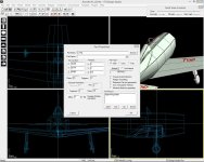
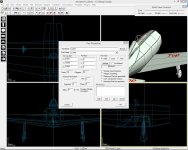
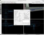
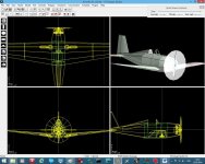
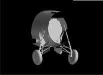
The first Aircraft 17, landing gear part 1
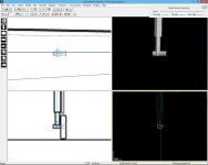
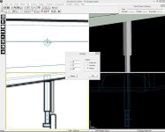
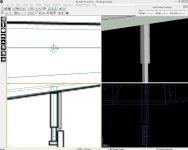
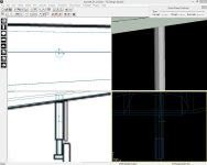
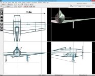
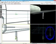
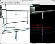
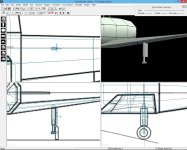
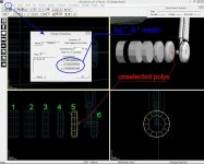
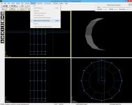
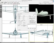
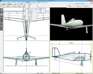
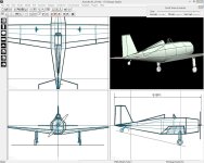
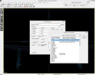
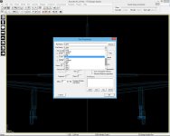
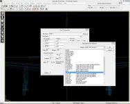
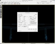
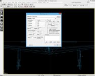
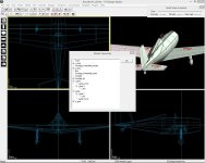
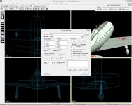
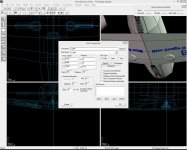
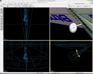
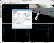
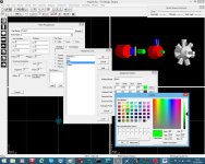
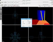
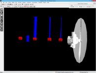
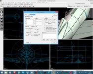
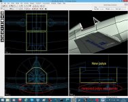
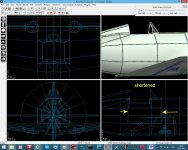
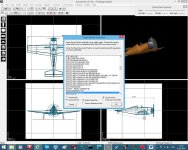
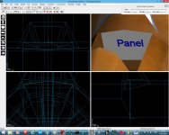
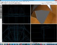
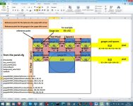
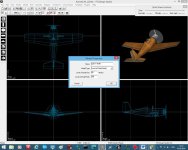
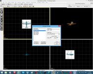
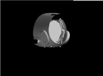
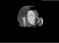
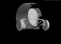
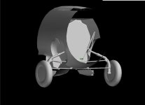
To make a landing gear we use a tube with 8 points and two sections, move the tube into position and size the tube to the drawing as shown in picture (picture 172). Now split both sections into a lower and upper section (picture 173), size the lower part again to the drawing but keep the “Y” length (press “constrain Y”)(picture 174),move the “X,Y,Z” down to the part (press constrain “X” and “Z” before) (picture 174). Now copy and paste the lower part one time, the second lower part will be the wheel axis, so we have to turn the part around the “Z” axis, so go to “Transform” and press “Rotate” write “90” behind the “Z” and make sure, you select “Vertices” at the right side (picture 175) than press OK. Now move the new part down to the wheel center, and size the part to the drawing as shown in Picture 176
 

Attachments

  • FSDS F4F Wildcat 28.zip
    51.6 KB · Views: 7
  • FSDS 176.jpg
    FSDS 176.jpg
    46.1 KB · Views: 4
  • FSDS 175.jpg
    FSDS 175.jpg
    56.2 KB · Views: 5
  • FSDS 174.jpg
    FSDS 174.jpg
    54 KB · Views: 5
  • FSDS 173.jpg
    FSDS 173.jpg
    53 KB · Views: 5
  • FSDS 172.jpg
    FSDS 172.jpg
    70.6 KB · Views: 5
Part #47

The first Aircraft 17, landing gear part 2
Next step will be to join both lower parts together, for attaching the tire it’s easier to take the axis part as main part, so select both parts and join them together (picture 177). For a later animation (Shock absorber) effect I lengthen the vertical part a bit into the upper part. Finally I smoothed the polys. No we go to the upper part, for the later animation we have to shift the X, Y, Z, axis upwards to a imagine turning point inside the wing (for a better handling make sure that you move only along the “Y” axis) smooth the poly’s also (picture 178). For the landing gear cover we will use a simple box that we size to the drawing (picture 179) if you like you can close all visible gaps of the tubes.
 

Attachments

  • FSDS F4F Wildcat 29.zip
    52 KB · Views: 7
  • FSDS 177.jpg
    FSDS 177.jpg
    62.1 KB · Views: 5
  • FSDS 178.jpg
    FSDS 178.jpg
    59.2 KB · Views: 5
  • FSDS 179.jpg
    FSDS 179.jpg
    74.9 KB · Views: 4
Part #48

The first Aircraft 17, landing gear part 3
Forming a tire: We will use a tube with 12 points and four sections, size the tube to the side view, than close the gap at the right side (select all right points in the back view window, than go to polygon and press “Make Poly from selected points”) (picture 180). Because a picture can show this process better than to explain it in words, please look at (picture 181) and into the source file. Finally I textured all new parts. I like to remark, that I smoothed only the outer polygons of the tires so select the outer polys first (poly Mode, -select Polys, go to edit press “polygon properties” and write “1” into the smoothing Group window and select “set” before you press “OK”) another remark: since windows 7 it will cause a failure message after pressing OK if in one of the “surface Normal” windows is only a “-0” in words “minus Zero”, just search for a poly where no “-0” is in one of the three windows, it doesn’t matter if it’s one of the selected polys or not, only the selected polys will be smoothed.
 

Attachments

  • FSDS 181.jpg
    FSDS 181.jpg
    67.6 KB · Views: 5
  • FSDS 180.jpg
    FSDS 180.jpg
    60.6 KB · Views: 5
  • FSDS F4F Wildcat 30.zip
    97.6 KB · Views: 6
Part #49

The first Aircraft 17, landing gear part 4
Unfortunately I posted always a source file with final named parts, so please start with “Aircraft_01_L18”; it’s in the Zip below. The zip contains always textured parts.
Before we are parenting the parts we have to create the left landing gear and the center gear by copy and paste, first copy each part of the landing gear and paste it, now it’s a routine job after copy the part, go to edit / Part Properties, look for Axis location “X” axis, you will see a number: 2.093, to switch it over to the left side, place a “-“in words minus before the number so it should be -2.093, than press OK, the part will move to the left side (picture 182), than go to “Transform” go down to “Flip” and press at the menu “Flip X” (picture 183). Do it with all 4 right landing gear parts. You will see that the left landing gear doesn’t fit the drawing, well, it’s my fault! The drawing is not as accurate as I thought. By the way if you ever made your own project you will find out that 3 view drawings even from good books are not as accurate as you think, often the top view doesn’t fit the side view.
For the center gear we copy only the lower gear part and a wheel than move both parts into position and fit them to the side view drawing, just use the “scale” button at the toolbar, make sure that constrain “X,Y,Z” are unlocked. The “X” Axis position should be “0” (Zero), in the second source file “Aircraft_01_L19” you will find all parts at the correct place. The center gear with adjusted “axis” (picture 184)
 

Attachments

  • FSDS F4F Wildcat 31.zip
    131.7 KB · Views: 4
  • FSDS 182.jpg
    FSDS 182.jpg
    86.8 KB · Views: 2
  • FSDS 183.jpg
    FSDS 183.jpg
    78.4 KB · Views: 2
  • FSDS 184.jpg
    FSDS 184.jpg
    75.1 KB · Views: 2
Part #50

The first Aircraft 17, landing gear part 5
For animations all landing gear parts needs their own correct name and parent part. The main Landing gear parts are those parts that are fitted to the wing, or to the fuselage (center gear). We start with the right main landing gear. Go to “Edit”, “Part Properties”, “Part Name” box and click on “Browse” select in category “aircraft keyframe animation” than select “r_gear” and press OK until all menus are closed (picture 185), now make the lower landing gear part current and repeat the action as before select “r_gear” (it will later appear as “r_gear.1”), for this part we need the right main landing gear as parent, so go to the “Part parent” box and select the at the drop down menu “r_gear” (picture 186) close all windows with “OK”. Next make the right tire the current part, again go to “Part Properties” this time use for the part name “aircraft stock animation” and select “r_tire” (picture 187), press “OK”. The r_tire needs also a parent part logical we select the lower landing gear part “r_gear.1” as parent (picture 188) close the menu with “OK” at last we have to rename and parent the Landing Gear cover, make it current, because it’s not an animated part itself, we can name the part as we like. I prefer Part names that are similar to the parent parts name with an extension to clarify where the part belongs in the part list. So name the part “r_gear_cover” and parent it to the “r_gear” (picture 189). The same proceedings are working for the left landing gear, but with different names (use: l_gear, l_gear.1, l_tire, l_gear_cover). The center gear an tire are following the same procedure but use for the landing gear “c_gear” (keyframe) and for the Center tire “c_tire” (stock animation) and the center gear as parent. To look at the Part Hierarchy, go to “Model” and select “View Hierarchy” (picture 190).
 

Attachments

  • FSDS 185.jpg
    FSDS 185.jpg
    61.9 KB · Views: 2
  • FSDS 186.jpg
    FSDS 186.jpg
    62 KB · Views: 3
  • FSDS 187.jpg
    FSDS 187.jpg
    67.2 KB · Views: 2
  • FSDS 188.jpg
    FSDS 188.jpg
    60.5 KB · Views: 2
  • FSDS 189.jpg
    FSDS 189.jpg
    66.8 KB · Views: 3
  • FSDS 190.jpg
    FSDS 190.jpg
    71.3 KB · Views: 2
  • FSDS F4F Wildcat 32.zip
    98.1 KB · Views: 3
Part #51

The first Aircraft 17, landing gear animations
Now we are going to animate the landing gears, in the last part #50 we gave the landing gear parts the correct names and parented them together. But we didn’t parent the main landing gear parts to the wing or the center gear to the fuselage.
If we look at the “part properties” of the “r_gear” we will see below “rotation” X: 0; Y: 0; Z: 0; (picture 191) (same with the “l_gear”), keep this in mind, than select for the “r_gear” the “r_wing” as parent part and press “OK”, you will recognize that the whole part turns outside, to fix this we have to make the “r_wing” the current part, go again to “part properties” and look under “rotation”, you will see next to Z: 6.5 (picture 192) keep the 6.5 in mind (or write it on a paper) close the part properties menu and go back to the “r_gear”, open again the “part properties” menu, go to rotation select the box behind “Z” and write -6.5 (in words minus 6.5) press “OK” (picture 193) this Number (-6.5) will be the number in the final animation frame for the right gear so keep it in mind or on paper. The proceedings for the “l_gear” are similar but the number must be (6.5) in “Z” rotation and the gear should be to the “l_wing” parented. The parent for the center gear “c_gear” is the “fuselage_aft” part. Because the “fuselage_aft” part hasn’t any rotation no other proceedings are required, you will see that the part has always a rotation at the “X” axis, this rotation will stay.
 

Attachments

  • FSDS F4F Wildcat 33.zip
    98.1 KB · Views: 5
  • FSDS 193.jpg
    FSDS 193.jpg
    80.1 KB · Views: 2
  • FSDS 192.jpg
    FSDS 192.jpg
    81.7 KB · Views: 3
  • FSDS 191.jpg
    FSDS 191.jpg
    79.4 KB · Views: 2
Part #52

The first Aircraft 17, landing gear animations
I will start again with the right landing gear part (r_gear) the proceedings for the left gear (l_gear) are the same but the “Z” axis angle is inverted, that means if the right gear angle is positive the left gear angle is negative or vice versa.
The landing gear animation starts with the retracted position so what we have is the extracted gear, or the animation end position. As we know from part#51 the “Z” axis has always a rotation of -6.5 (Part Properties) keep this position (-6.5) in mind. Select at the main toolbar “Rotate”, set constrain “X” and “Y”, go to the back view window and turn the gear in until the landing gear cover part isn’t visible go to part Properties, an look at the “Z” axis Rotation it’s now -90.5 that’s the starting point of the animation (picture 194). Do the same with the left landing gear, to keep it easy, select the (l_gear) and open part properties write into the “Z” axis rotation 90.5
Animation start right gear (r_gear) -90.5, end -6.5; Animation start left gear (l_gear) 90.5, end 6.5
Make the r_gear current select “Animate” and “Animation Mode” at the main Toolbar make sure the frame is “Frame 0” than click on “Set Key Frame” (picture 195)Frame 0 appears now with a little star (Frame 0*). Now go to Frame 100 press left or right arrow at your keyboard or at the main Toolbar, open “Part Properties” and write into “Z” rotation (-6.5) and click on OK (picture 196) the gear is now in the extracted end position, now go again to “Animate” and “Set Key Frame” (Frame 100*) now go to Frame 200 and “Set Key Frame” again (Frame 200*) finally go to Frame 0* and leave the animation Mode, the moves up into the retracted position, the proceedings for the left gear are the same make the l_gear current part, animation mode use inverted settings for the “Z” axis.
It’s on your own to animate the center gear.
In #53 we will look at the shock absorber animation
 

Attachments

  • FSDS 194.jpg
    FSDS 194.jpg
    74 KB · Views: 2
  • FSDS 195.jpg
    FSDS 195.jpg
    87.3 KB · Views: 3
  • FSDS 196.jpg
    FSDS 196.jpg
    80.8 KB · Views: 2
  • FSDS F4F Wildcat 34.zip
    98.3 KB · Views: 5
Part #53

The first Aircraft 17, landing gear animations
For the shock absorber effect we will use keyframe 100 to 200, we start with the right landing gear part “r_gear.1”. Because we will animate this part only alongside the “Y” axis, press constrain “X” and “Z”.
Set “Animate / Animation Mode” look if the keyframe counter is “Frame 0” if yes press “Set Key Frame” now go forward to “Frame 100” than move the part slightly a bit down and press “Set key Frame” again (At the “Part properties” menu “Y” axis location – 1.189 before moving, after moving -1.259, keep this last number in mind for the l_gear.1) (picture 197).Now go to “Frame 200” and move the part back to the original position (-1.189) and “Set Key Frame” go to “Frame 0” and leave the Animation Mode. Select “l_gear.1” and repeat the steps from the r_gear.1. Contrary to the upper gear part “l_gear” the (-/+) settings are not inverted. The center gear is slightly different to the main gear because its only one animated part. Because we always animated “Frame 0” to “Frame 100” we have just to add the shock absorber effect in this case only “Frame 200”, therefore we turn the center gear just a bit upwards alongside the “X” axis, than press “set Key Frame” (picture 198)
The landing gear animations are finished
Next part will be the engine and prop
 

Attachments

  • FSDS F4F Wildcat 35.zip
    98.4 KB · Views: 5
  • FSDS 198.jpg
    FSDS 198.jpg
    78 KB · Views: 2
  • FSDS 197.jpg
    FSDS 197.jpg
    80 KB · Views: 2
Part #54

The first Aircraft 18, Engine and Prop
Before I start with the engine, I separated the cowl part from the fuselage copied it, inverted the polygons and textured the now internal part, you will find the new texture File in the texture folder, I also made an engine firewall, so you can’t look through the aircraft anymore. The Cowl part has its own name “Cowl0” and if you look at the “Part Properties” I added to the pre process window “Engine 1 Visible”.
-Updated Zip-


Attachments

  • FSDS F4F Wildcat 36.zip
    120.7 KB · Views: 3
Part #55

The first Aircraft 18, Engine and Prop
I don’t want to explain how to build the engine itself, I think the Picture 199 will show it much better than (my) words can describe it. About the picture, we can give the polygons different materials as you see in the picture I gave all parts its own color.
To add Material (Picture 200), go to “Part Properties” Click on “Material” than a new menu opens called “Material List” Click on “Add” the next menu opens, called “Material Editor” here you can give the new Material its name, now click on the upper “Select” button, a last menu opens where you can select the color you want. The “diffuse color” is the Material itself, if you edit the number below “Alpha” you can make the Material transparent if you want. With the “Specular Color” you can edit the gloss effect color; the “Emissive Color” makes the object glowing (for lights), the last line is for “Specular Power” here can you edit how glossy the part appears in the game.
You can add different Materials to one object for example: red and blue polys; but if you add a transparent material to one poly of the object the whole object will be transparent.
To make the cylinder’s; Before you make the other cylinders texture the main cylinder then copy the main (top) cylinder, go to “Transform” at the main Toolbar, select “Rotate” and write 51.428 (360/7=51.428; (7) because of 7 cylinders) make sure that “Vertices” are selected than press “OK”, only the vertices had rotated now copy the new cylinder rotate the vertices again, now follow up until you have 7 cylinder (Picture 201). (In the Zip is only the engine itself)
 

Attachments

  • FSDS 199.jpg
    FSDS 199.jpg
    51.9 KB · Views: 2
  • FSDS 200.jpg
    FSDS 200.jpg
    90.8 KB · Views: 2
  • FSDS 201.jpg
    FSDS 201.jpg
    59.7 KB · Views: 2
  • FSDS F4F Wildcat 37.zip
    111.1 KB · Views: 3
Part #56

The first Aircraft 18, Engine and Prop
Like the engine I also made a picture of the “Prop building” process, so please look into the source file (Picture 202)
For the Prop animation we need the Prop itself and two copies of the prop. The first prop is named “prop_still”, as the name always said it’s the still standing prop, the next “prop” is the “prop_slow” for a slow moving Prop, and the last prop is a bit special, the fast moving prop, “prop_blurred“, is build out of 3 parts, the prop axis without prop blades and two disks with a blurred prop texture one disk for the front side and one disk for the back side. Don’t join the disks together! Parent the disks to the prop blurred axis. Both disks are transparent parts, for the transparent material please look into the material list.
 

Attachments

  • FSDS F4F Wildcat 38.zip
    126 KB · Views: 6
  • FSDS 202.jpg
    FSDS 202.jpg
    45.8 KB · Views: 2
Part #57

The first Aircraft 19, Virtual Cockpit 1
For a better looking aircraft I made a cutout for the Cockpit
For the virtual cockpit we need some inner structures, with the current model we have only outer polys, so we copy and paste the “fuselage” part and name it “Fuselage_inside” than go to “poly mode” select all polys, go to “Polygon” and press “Flip all selected” finally parent the new part to the “fuselage” (Picture 203)
Next remove the unused polys from the bottom than create 2 new polys for the cockpit floor and two polys for the front and rear wall as shown in (Picture 204). Finally we should have a 5 side closed cockpit compartment.
At last we make the cockpit “Fuselage_inside” part a bit shorter and texture the new part. (Picture 205)
 

Attachments

  • FSDS 203.jpg
    FSDS 203.jpg
    108.5 KB · Views: 2
  • FSDS 204.jpg
    FSDS 204.jpg
    108.3 KB · Views: 3
  • FSDS 205.jpg
    FSDS 205.jpg
    102.9 KB · Views: 3
  • FSDS F4F Wildcat 39.zip
    167.5 KB · Views: 3
Part #58

The first Aircraft 19, Virtual Cockpit 2
There are two steps to insert the virtual Cockpit: first, click on “Model” at the main toolbar, and then click on “Add Model”, a new popup menu “Model Properties” appears. Write Virtual Cockpit or simple VC into the box behind “Name”. Go down to “Model Type” and select “Aircraft Virtual Cockpit” click on OK (Picture 206), you will be transferred into the Virtual Cockpit model which is empty.
Second, go back to the main model by clicking on “Model” at the main toolbar, than select “Manage Models” and select “FSDS Model” (Picture 207) you are back to the main model. Now go to “Edit” press “Select All” (all parts are yellow one green) press on “Copy” (Picture 208) now go to the virtual cockpit model (Model/Manage Models/Virtual Cockpit) and past the copied parts into the virtual cockpit model. Go to Edit and “Unselect All” parts, than go back to the main Model and unselect all parts also. Now we are ready for a first test flight.
 

Attachments

  • FSDS 206.jpg
    FSDS 206.jpg
    78.9 KB · Views: 2
  • FSDS 207.jpg
    FSDS 207.jpg
    49.7 KB · Views: 2
  • FSDS 208.jpg
    FSDS 208.jpg
    87.5 KB · Views: 2
  • FSDS F4F Wildcat 40.zip
    193.2 KB · Views: 3
Part #59

Intersection, converting to CFS2 #1
Before we convert the new aircraft, we have to set up the aircraft in CFS2, so go into your CFS2 aircraft folder select the “F4F4_WILDCAT” and make a copy of this folder into the aircraft folder Rename the copied folder into whatever you like, I use “FSDS_First_Aircraft”, open the folder and then open the “Model” folder, open the “model.cfg” file with “Editor” or “WordPad”, there is a line “normal=F4F4_Wildcat” change it into “normal= FSDS_First_Aircraft”, there is a MDL file rename this file to “FSDS_First_Aircraft” also(Picture 209). It’s important that the “MDL” file has the same name as written in the “cfg” file. Leave the “model” folder and open the “aircraft.cfg” file
Right at the top of the file you find [fltsim.0] below this line “title=FSDS First Aircraft” in this line you can give the aircraft the name you like, below the “title” line you find “sim=FSDS_First_Aircraft” (remark, I changed always the names to the new one), the “sim” line defines which Damage profile (.DP) file and which Air file (.Air) the aircraft should use. So rename the DP file and the air file into “FSDS_First_Aircraft” (Picture 210). Before you close all folders open the “Texture” folder and delete all files.
Extract the content of the zip and past the Aircraft folder into your CFS2 Folder. (The MDL in the zip is a simple box to keep space)
 

Attachments

  • AIRCRAFT.zip
    36.5 KB · Views: 3
  • FSDS 210.jpg
    FSDS 210.jpg
    82.5 KB · Views: 2
  • FSDS 209.jpg
    FSDS 209.jpg
    43.9 KB · Views: 3
Part #60

Intersection, converting to CFS2 #2
Back to FSDS2.24 open your actual aircraft “Aircraft_01_L27” file, then click on the little Aircraft sign (aircraft File (.mdl)) at the main toolbar, a menu “Flight Model selection” opens, and search for “FSDS First Aircraft” click on it, check the little box before copy textures and finally press “OK” (Picture 211). , now your aircraft source file will be converted into a MDL file and the textures will be moved into your aircraft Texture folder.
Before you start the aircraft in CFS2 you have to convert the textures into a format that CFS2 can read therefore you need a program that can convert bmp in to DXTbmp. Or simple drop the always converted textures in the zip below into your Aircraft texture folder.
Finally you have to adjust the “Virtual cockpit” view point, and the contact points for the landing gear.
 

Attachments

  • TEXTURE.zip
    345.3 KB · Views: 3
  • FSDS 211.jpg
    FSDS 211.jpg
    89.4 KB · Views: 1
Part #61

The first Aircraft 19, Virtual Cockpit Panel For a simple panel I added a 5 point poly to the model, named it “Panel”, textured it and parented it to the fuselage, -than copied it and added it to the virtual cockpit model (Picture 212). This is only for the Virtual Cockpit! not for the main model! For the working gauges we have to add a square! polygon slightly in front of the panel, size it to the panel, don’t care if it’s overlapping the panel, you will not see it in the game, this part is for display the gauges in the virtual cockpit (Picture 213). So name it “Gauges” and parent it to the Panel. The texture is a bit special because we will use a texture that doesn’t have to be in the texture folder. So first we texture the “Gauges” part as before (Part / Textures / Part Texture Assignments / Back Texture) click “Select” and add the gauges texture “$pan1” to the list. Now select the texture and click on “OK” now go to “Properties” and check the little box “Invert Y” (Picture 214), press OK, now remove the “.bmp” from the list and press OK (Picture 215).
 

Attachments

  • FSDS 212.jpg
    FSDS 212.jpg
    93.6 KB · Views: 5
  • FSDS 213.jpg
    FSDS 213.jpg
    92.6 KB · Views: 4
  • FSDS 214.jpg
    FSDS 214.jpg
    107 KB · Views: 4
  • FSDS 215.jpg
    FSDS 215.jpg
    114.9 KB · Views: 6
  • FSDS F4F Wildcat 41.zip
    503.1 KB · Views: 7
Part #62

The first Aircraft 19, Virtual Cockpit Panel To edit the Aircraft Panel there are a few things good to know. The upper left corner of the gauges part is the reference point where the measurement start, you can set the pixel in the “panel.cfg” to a game conforming size (128x128, 256x256, 512x512 or 1024x1024) (Picture 216). For the gauges: all gauges for CFS2 are based on square textures also, the reference point is also the upper left side. For more details please look at Picture 217. For the model I added the modified stock F4F4 Wildcat panel just unzip and replace the panel folder into “FSDS_First_Aircraft” folder.
 

Attachments

  • FSDS_First_Aircraft PANEL.zip
    346.8 KB · Views: 3
  • FSDS 217.jpg
    FSDS 217.jpg
    124 KB · Views: 4
  • FSDS 216.jpg
    FSDS 216.jpg
    66.3 KB · Views: 4
Part #63 Final part

The first Aircraft 19, Multi Lod model The process to add multilod models is similar to adding the Virtual cockpit, the menu so go to “model” and select “Add Model” in the popup window “Model Properties” select “Level of Detail Model” and add a first LOD model, gave the model its individual name instead the “FSDS Model” standard name, I use Lod model names Like “LOD 1 100 80” (Picture 218). I included a LOD model demo where you can look into the source file and you can play around the settings, each LOD has its own color, if you convert the model to CFS2 make a test flight in mission builder where the new aircraft is the “ai” aircraft if you get closer to the “ai” the color will change. For the First aircraft model, I made a copy (select all) of the main model and past it in the first Lod (LOD 1 40 90) then stripped polys made a copy of the LOD 1 model and past it into the LOD 2 model, stripped polys… and so on. LOD 4 and 5 are very simple models like the “LOD demo” model. There are two zip files one with the source files and one with the flyable CFS2 aircraft That’s the end of this tutorial.
 

Attachments

  • FSDS 218.jpg
    FSDS 218.jpg
    67 KB · Views: 6
  • FSDS 219.jpg
    FSDS 219.jpg
    71.9 KB · Views: 4
  • FSDS 220.jpg
    FSDS 220.jpg
    105.5 KB · Views: 4
  • FSDS F4F Wildcat 42.zip
    1.7 MB · Views: 3
  • FSDS_First_Aircraft.zip
    1.7 MB · Views: 3
Landing Gear Animation

One of the most complex animation’s I ever made.

wolfi
 

Attachments

  • Animation 01.jpg
    Animation 01.jpg
    17.9 KB · Views: 3
  • Animation 02.jpg
    Animation 02.jpg
    21.5 KB · Views: 2
  • Animation 03.jpg
    Animation 03.jpg
    24.9 KB · Views: 3
  • Animation 04.jpg
    Animation 04.jpg
    26.3 KB · Views: 3
  • Animation 05.jpg
    Animation 05.jpg
    26 KB · Views: 3
Wow! This has been an excellent series start to finish. We have been needing this one for a long time, We really appreciate all your efforts to make this available to new and budding designers. Thank you so much :applause: :medals: :medals: :medals:
 
Back
Top