• Guest Please check out the Help Wanted thread in Ickie's NewsHawks.
    The future of the Outhouse depends on you!
    Help Wanted

UVW Mapping in Gmax tutorial series

With scenery, consider viewing distance, and frame rate friendliness. E.G. will there be 50 copies of this in one scenery area? How close will the building or fence be to passersby?

To get a sense of what you should be using, look at scenery files you have and how they display at typical viewing distances.

Also, please visit FSDeveloper for guidance as they have a large group of scenery developers there.

http://www.fsdeveloper.com/forum/
 
The (seemingly) obvious solution was 'more pixels/inch'. I re-saved at 300 dpi. Gmax couldn't load a file that big, (1.3 Gb) So I re-saved again at 120 dpi. This time it loaded just fine, but was just as pixelated. The 'dpi/quick fix' didn't work.

The DPI setting in Photoshop is for printing purposes only and has no impact on FS.

What I do is make my textures at a pitch of 10 pixels per foot.

So a 1024 wide texture will cover 102.4 feet of surface on my model. Actually a bit less as you never want to map to the edge of your texture. I leave at least a 2 pixel border on my textures that is unmapped.

For the side of a building that is 20 feet long by 10 feet high I need 200x100 pixels of texture real estate. At that resolution things look real nice in the sim.

For buildings that you cannot get real close to in the sim you could use less pixels per foot.

Note that you should try to use the same resolution on all of your building or you can get some blurry textures in the sim.

cheers,
Lane
 
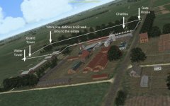
Thank you all for the come-back. I may be in better shape than I feared. First, my objects will never be seen close-up. Check the image below. This is the German airfield at Boistrancourt. In "Wings Over Flanders Fields" (modded from CFS3) the default airfield is a few hangars and revetments. (seen at the far left of the pic.) The rest (a sugar factory) has been built from existing buildings in CFS3 by RAF_Lou. My job is to build a brick fence around the chateau/estate; a series of modules, each 60' x 10'. Also a guard tower, a water tower, some wood fences and re-build the revetments. The building is done.

The runway (direction of take-off) is to the left. Direction of Final Approach is from the right, over the factory. No observer will get anywhere near my models.

What I need then, is a tutorial on importing and placing my test model in CFS3.
.

attachment.php
 

Attachments

  • CFS3 2015-01-05 18-05-30-80.jpg
    CFS3 2015-01-05 18-05-30-80.jpg
    95.6 KB · Views: 16
I thought my last question (how to export from Gmax--import and place in CFS3) would be an easy one. If anyone knows the answer to this one, it's got to be you guys here at SOH. Don't want to be a pest, but I'm so close on this I'm chewing my nails.
 
I thought my last question (how to export from Gmax--import and place in CFS3) would be an easy one. If anyone knows the answer to this one, it's got to be you guys here at SOH. Don't want to be a pest, but I'm so close on this I'm chewing my nails.

I can't help you with CFS3, maybe a post in the CFS3 forum would get more attention.

cheers,
Lane
 
I've been struggling with UVW mapping in Gmax even after following all the tutorials I can find. I'm sure there's something simple that I'm overlooking.

I create something as simple as a 3d box, and leave it as an editable mesh making sure to have nothing selected when I close mesh modifier. I then do a mesh select, choose face, and select my faces on one side, use a planar map and setup the gizmo and stuff per Miltons tutorials. I do this for all 6 sides. Now here's where it goes south, when I select an unwrap UVW modifier on the top of the stack, the only faces I can edit in the unwrap window are the last faces I mapped. I've tried what is shown in the tutorials and I can't seem to get any other sides of the box to show up in the unwrap window other than the last one I mapped. The ONLY thing that works is to collapse the entire stack before applying the unwrap modifier.

Is that the 'correct' way to do this ?

Edit- headdesk, NEVER saw this reply in the few years I've been trying to figure this out:
I have often regretted that screenshot: having mapped all five sides, just apply Edit Mesh>Unwrap UVW and then Edit. I was trying to show how simply applying an Unwrap would not show the mappings of the entire object.

Also, when mapping each individual group in the mesh select modifier, is there a way to hide just those faces so I can't select them in the following mesh select grouping ?
 
I've been struggling with UVW mapping in Gmax even after following all the tutorials I can find. I'm sure there's something simple that I'm overlooking.

I create something as simple as a 3d box, and leave it as an editable mesh making sure to have nothing selected when I close mesh modifier. I then do a mesh select, choose face, and select my faces on one side, use a planar map and setup the gizmo and stuff per Miltons tutorials. I do this for all 6 sides. Now here's where it goes south, when I select an unwrap UVW modifier on the top of the stack, the only faces I can edit in the unwrap window are the last faces I mapped. I've tried what is shown in the tutorials and I can't seem to get any other sides of the box to show up in the unwrap window other than the last one I mapped. The ONLY thing that works is to collapse the entire stack before applying the unwrap modifier.

Is that the 'correct' way to do this ?

Edit- headdesk, NEVER saw this reply in the few years I've been trying to figure this out:


Also, when mapping each individual group in the mesh select modifier, is there a way to hide just those faces so I can't select them in the following mesh select grouping ?

MDK,

You should collapse the stack before using the unwrap modifier, or you can do it after each uvw map is added.

I created a video for you explaining it all.

Also, get in the habit of assigning a material id to all polys before mapping. It makes the process go much faster and you can ensure you haven't missed any polys in the selection or mapping.

https://www.dropbox.com/s/n7d60brhn0iexnq/mapbox.zip?dl=0

TY sir. I knew it was something stupid. I didn't want to collapse the entire stack unnecessarily incase I needed to fix some mapping, and I couldn't undo back that far.

So, select poly (or faces), assign ID, map, then collapse. Will give it a shot.
 
TY sir. I knew it was something stupid. I didn't want to collapse the entire stack unnecessarily incase I needed to fix some mapping, and I couldn't undo back that far.

So, select poly (or faces), assign ID, map, then collapse. Will give it a shot.

Yes, and remember to assign material ids to each poly(s) you want to map separately.
Set your poly(mesh) Select, select by ID, add uvw, collapse.

If you make a mistake or oversight, just redo the process for the incorrect polys.
 
Yes, and remember to assign material ids to each poly(s) you want to map separately.
Set your poly(mesh) Select, select by ID, add uvw, collapse.

If you make a mistake or oversight, just redo the process for the incorrect polys.

:dizzy:
I noticed on your video that you had assigned poly's ID's before even doing the poly select modifiers. Are you doing this within the editable poly modifier, or did poly selects and assigned ID, then collapsed before the currently shown select and mapping sequence ? Are you doing all the assigning BEFORE actually assigning a material to the object ?

Just to keep it simple, I'm trying to use a standard material (MatID=1), so is there a sequence I have to map (i.e. Left,top,right,front,bottom,back) and/or does each following mapping from te base object need to touch each other ?

MDK,

Material IDs are assigned automatically when the object is created.
However, you can select each poly and change the material ID as you wish, after you assign an Editable Poly/Mesh to the stack.
You should assign material IDs before you start mapping.
You do NOT have to assign a material to the object before mapping.
There is no specific mapping sequence required.
You can anything, anytime.
No, you do not have to break the sides apart; map as one object.

Once mapping is done (collapse the stack if you have not done so), add a Unwrap UVW to the stack.
I think I understand.
Since my material is already created, I shouldn't apply it to the object until after it's mapped and collapsed ? Since I understand the the matID on the select screen corresponds to a MATID layer on a multilayer material, collapsing the stack also collapses the MatID assignments in the mappings allowing the entire editable object to be assigned to a single level ID (standard material) ?

Actually you can apply your standard or multi-material anytime AFAIK; it does not matter.

You have a lot of flexibility to assign, reassign selections to any part of a material you wish.

I use Lithunwrap to create a texture sheet so I usually do that last.

But once assigned and mapped, you can move your poly selections around on the texture sheet in the Edit Unwrap to fine tune your placement if needed.
The key thing is using the channels to manage the polys in each group so when you edit, you can select the individual channel set of polys to manage location on the texture sheet as you need to.

After about 5 hours of practice I got the hang of this. As you explain, it IS rather simple but unfortunately I still have the same result- unmapped faces, that cannot be mapped to.

Instead of fighting these faces in the main aircraft model I created a new model by deleting every object except the one I'm trying to map, as well as ALL the materials. I then save the model with a different filename, and exit and restart Gmax, then open the new file. I then change the object name to ensure when I import it into the main aircraft model it's not a duplicate of an existing object, create a new standard material and map the object. Everything looks great, all the faces are mapped just how I want them so I collapse the stack and I save the UVW's and unassign the material and delete it. I then save the the entire model again with a different name and close down Gmax.

I'm now ready to import the newly mapped part so I open Gmax again and load my aircraft model. I unassign the material from the part I'm going to replace, then delete the part. I use the merge function to import the mapped part from the above paragraph and am expecting my job to be done. Now that it's imported I select the part and assign the material. This is the same BMP I used to create the material in the above file. I look at my newly imported part and notice 2 of my face groups aren't showing the texture, they're just flat grey. They appear to have no reflectivity as well so I check the normals on those faces and they are still projecting in the correct direction. I then select the faces and flip the normals thinking maybe the faces flipped during the import but watch them turn invisible on the flip, so I undo the flip. I then do a mesh select modifier and select the faces which are still properly grouped from the original mapping, and do another UVWunwrap and see the item is still in it's correct position on the material.

So I'm at a loss now what to do next.

I've had this happen a few years ago with a different model, a few faces didn't survive the import from Milkshape but I stumbled on a post somewhere describing how to reverse the vertex order of a face in Gmax, but have long since forgotten how to do it.

ANY suggestions how to fix this ?
 
MaddogK:

No expert, but like yourself - still crossing many of these learning hurdles, I think you may have 'trapped' yourself and overcomplicated your mapping sequence.
I've had myself in several tight corners - thank heavens Milton has always bravely pulled me out of the deep water!
(Thank YOU Sir!)

As Milton says, there's massive built-in flexibility allowing all manner of awesome applications and variations.


I'd recommend one more stab - in these stages.


1. Create NEW material.

2. Apply material to ENTIRE part NOT polys.

3. Map and collapse each side.

4. UVW unwrap for any fine tuning, collapse.

Hope this helps - Good Luck!

Nigel :encouragement:
Funny thing is just last week I did a cleanup of my fuselage and some tweeking of the nose shape. I split it right down the center nose to tail and deleted one half so I could work the cleanup on the remaining side, then clone it to the other side when finished. When all was done and exported into flightsim I found I had an entire fuselage that was textured in-side-out even tho the normals were facing the correct direction. I still havent figured out how/why Gmax would project the normals out of the backside of the poly's, and flipping the normals only made the inside textures even darker.

*shrug

I ended up deleting the newly created side, flipping the normals on the other side, then mirroring, deleting the original side, selecting the copy and mirroring it back to replace the original, then selecting ALL faces on the entire object and flipping all the normals.

If there was only a way to flip the face without flipping the normal. I'm even worse at normal aligning than I am at brain surgery.
:)
 
Originally Posted by MaddogK
...I still haven't figured out how/why Gmax would project the normals out of the backside of the polys...


Oh boy, does this bring back some memories!

To quote the tutorial series this thread was originally announcing:–

UVW mapping ... controls how and where a texture file is projected on to a model.


When you map a selection of polys, the mapping determines from which direction a texture is projected on to the polys. That's what View Align when applying a UVW Map modifier does. If the left side of a fuselage has been mapped as if the texture is projected from left of the fuselage, then a cloned left half, mirrored to make the right half, will have the same mapping as the left half:–


xwWjKCb.jpg


ZSbWgal.jpg


1wP5ho3.jpg


I hope this helps.
 
Last edited:
The right side can be remapped or have its mapping edited to avoid confusing sides on the texture sheet.

FYI, some models have both sides of the fuselage apparently mapped from the same direction (eg Vertigo F8-F Bearcat) so the texture for one side will seem back to front. This is not a mistake, it's all to do with how the modeller arranged the mappings on a texture sheet and it's up to you how you arrange yours. Just have a thought for the painter: he/she (or you) may curse an idiosyncratic layout.
 
Back
Top