Boeing Stearman Model 75

Hello Aleatorylamp,

I don' think you really understood what I was trying to tell you.
I just stated that the fixed pitch propeller and engine RPM limits might be a reason the maximum speed would not increase.
OTHER performance such as climb and acceleration should improve though, even with the same propeller.

I would still suggest you research what the R-680-11 specifications actually were.
If you can find what Lycoming's model number was for this engine, I can probably find some specifications, but I don't have anything directly related to a "-11" engine.

Regarding building your own propeller tables:
Do you know what model of propeller you intend to use and what its specifications were?
Diameter and Pitch would be absolutely necessary (obviously) and those varied a bit between the different propeller options.

Regarding the 124 MPH versus 135 MPH, there may be more than just the 300 pound weight difference between the PT-17 and later models. Perhaps there is something aerodynamic that we don't know about?

- Ivan.
 
Hello Ivan,
I was trying to keep my post short, so I didn´t mention the increase in RoC and Accelleration, because you had mentioned that before anyway.

There are only three different sources quoting 280Hp engines on 255 stock -13B´s, and 6 -13C re-fits, and the top-speed reference (if given) is the same as for the standard engines. Then, there are twenty+ times more sources and the FAA certificate that simply do not mention this engine.

Either it is simply mistaken information, or perhaps not mentioned, because it seems to have been a stop-gap measure to continue supplying trainers, when there was a serious shortage of B engines in 1940 and 1941. Maybe this was covered up, or maybe it was just ignored as being not important.

Do all sources coincide with the first PT-17 as being 300 lb lighter? There are many that just bundle it up with the rest. I did a test using a 225 Hp Lycoming R-680-11 with 5.5 compression, and the top-speed difference with 300 lb less and a 43 USG tank instead of a 46 USG one was only 0.5 mph. Not that I want to argue, but it´s just strange.

Either way, it is interesting in the sim, that with the same airframe (i.e. .air file), just the change from 220 to 280 Hp brings about an increase from 124.2 mph to 135.4 mph. The propeller tables involved are of course not perfect, but the results are approximate. The fixed pitch prop seems to work quite well at 22 degrees.

Then, I don´t think there were any aerodynamic refinements on the airframe - they always mention that it was all basically the same.

I have also noticed two types of top speed mentioned, apart from the Vne of 186 mph, which also appears as "top speed" in some places: One is a contiuous top speed, and one just simply a top speed. Thus, max. continuous could be the 124 or 125 mph generally quoted, and the 135 mph could be a 5-min max. speed of 135 mph. All very misleading...
One source actually quotes 124 mph as Vno.

A couple of sources also just don´t quote any top speed at all - how convenient - just cruise, stall and Vne.

I have also done experiments with the supercharged engines for other models with CV propellers, albeit adjusting Torque Table values, and reached approximate results that were perhaps a bit low, because the 157 mph top speed for the 450 Hp version was only 150 mph, and the 600 Hp version gave 170 mph. All under the 186 mph Vne.

I got (I think) quite good results for the 360 Hp version though, which had no supercharger, that gave 145 mph and a CV prop. But we don´t know the top speed of the model with that engine either.

On all these experiments I only changed Horsepower and max. RPM (and Torque to get the HP with the RPM), and the rest of the airframe stayed the same.

Incidentally, I have found all the information as to diameter and mean pitch angle and its position on the prop, but from that point, to a point where I´d be knowing what to do with this info, there´s a long stretch, so I can´t do it. The wooden prop seems to have been 4 inches smaller than the metal one - 98 as opposed to 102 inches, and there was a metal one which was a ground adjustable one. But, information is very confusing.

Anyway, I´m not too bothered by all this, and even without any specialized refinements on the propeller tables, .air file performance results can be fine tuned quite well to get what one would be looking for, once it is clear what one is looking for, of course!

Well, in view of all this, and that I´ve further refined my drawings, I´ll start building.
The straight wings look very enticing for buiding as structures, all but the rounded wingtips.
Initially I was worried about their thickness getting a bit thinner going outwards on some drawings, but that is not the case as seen on photos and other drawings. Some allegedly precise drawings don´t even give a dihedral for the top wing...
There´s a horizontal centre bit and top dihedral is 0.5 deg, with 3 deg. incidence, and the bottom wing is 1.5 deg. dihedral, and 4 deg. incidence. So, this should not be too difficult to build.

Anyway... let´s see.
Cheers,
Aleatorylamp
 
Last edited:
Hello Aleatorylamp,

Glad you were just simplifying for brevity.
When you stated "- there´s little point. First of all, as Ivan says, performance would be limited by the propeller anyway", it seemed like you were not understanding all the other performance gains as a result of extra power.

Your testing with a fixed pitch propeller is at an angle of 22 degrees.
I haven't done as much reading, but I believe the pitch of the stock propeller would only be about 9 degrees or perhaps 10 degrees.

Take a look at some propeller efficiency graphs which can easily be found online and do a comparison between the maximum efficiency of a 10 degree pitch as versus a 20 degree pitch.
Be careful that you are looking at graphs for Aircraft Propellers and not Naval Propellers; The curves are a bit different though they look quite similar.
If the efficiency is very different, then one has to wonder how much drag has to change to come up with the SAME maximum speed.
If Drag is different, then what is it doing to the rest of your flight model????

I had already mentioned a few times in other threads that weight differences really don't seem to significantly affect maximum speed but they do affect acceleration and especially climb rate, so the 300 pounds less weight making no significant difference is not a big surprise.
Since we are on weight differences, did you also alter the Zero Fuel Weight in your AIR file when testing with the higher powered engines?

From what I see in the FAA Type Certificate:
The R-680 E series engines were about 40-50 pounds heavier.
The R-985 was about 150 pounds heavier.

As I have commented before, the FAA Type Certificate has a great deal of information but you must understand the context in which it was written.

- Ivan.
 
Hello Ivan,
Thanks for your detailed post. I´ll try 9 or 10 degree pitches then. I´ll take a lot of adjusting elsewhere, I suppose. But... what a flat propeller! How can you get it to bite the air at only 2000 RPM if you are moving at over 100 mph? I wonder.

I still don´t understand why you want me to alter the drag parameters to get tdifferent speeds, if basically all these planes had very similar airframes, especially the military ones.

As regards propeller pitches, it is too complicated for me to understand exactly what´s going on, so I prefer not to try and tamper with the tables.

Given that the default reading for fixed prop pitch angle in the .air file is 20 degrees, I supposed that this was the best for a fixed pitch prop. I got better results using 22 deg.
Anyhow, I can try and see what happens with 9 or 10 degrees.
I didn´t know that - thanks for the info.

My experimentation on the post war acrobatic 360 Hp, 450 Hp and 600 Hp versions were all just to get a general feel. Howerver, I will correct the weights for the different engines. I should have noticed - thanks for the tip. I obviously have already noticed tremendous differences in RoC and Accelleration. All those horses in the nose certainly made a LOT of difference compared to the normal 220-225 Hp motorizations.

Incidentally, lengths seem to vary also (!!!!) depending on the source, and quite indistinctively of model type:
23 ft 4 in (possible typo)
24 ft 3 in
24’ 09”
24’ 10”
25 ft
25 ft 1 in
The second one seems most reliable, as other lengths interfere with the scales on the drawings.

Anyway, I don´t think things have to be so complicated, because a good visual and a good flight model will come out of all this general testing anyway (not that the flight testing will affect the visual model, of course... here I meant the testing to see what the different lengths would do to the scales on the drawings).

I know you are much more exact with performance and power details, and my general tests to arrive at a reasonable conclusion for a usable flight model probably raise the hair on the back of your head and seem preposterous from your point of view, but I just haven´t got the necessary insight to be able to do it with greater accuracy.

Anyway, not to worry, it´s going very well!
Let´s see if I start making the plane...

P.S. I´ve got clipped wings done for the moment.

Cheers,

Aleatorylamp
 
Last edited:
Aleatorylamp said:
I can also use a nice and shiny bronze fishing-boat propeller.
Ha ha! Just joking. I did notice there are naval screw graphs, don´t w

Hello Aleatorylamp,

Why did you edit out the "fishing-boat propeller" for?
I thought it was a pretty good joke.

I didn't just pull that 9 or 10 degrees out of the air. If you look at the FAA Type Certificate, it describes quite a few of the propellers that are useable in these aeroplanes.
Unfortunately they did not specify the pitch of the wooden Sensenich propeller but the weight and diameter and gave some RPM data to derive the power coefficient at zero forward speed and full throttle.....
To guess at the pitch:
You will find that 9-10 degrees falls within the range of the adjustable pitch propellers.
Coarser pitch propellers for this aeroplane seem to be associated only with the higher powered engines that were not original equipment.
Perhaps my guess is wrong. As I said before, I have not done the research but note that even the 450 HP Constant Speed Propeller does not go up to 20 degrees IIRC.
If you have found a good source for information, by all means, use it. My numbers are only a guess as I stated before.

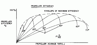
Regarding Drag differences, please look at the attached Propeller Efficiency Graph.
You can probably find a better one but though it may be different in detail, the substance will be the same.
Efficiency at 45 degrees appears to be around 87%
Efficiency at 20 degrees appears to be around 75%
Efficiency at 10 degrees appears to be around 53%

Now imagine how close your Drag numbers would be if you are getting 125 MPH with 75% propeller efficiency when in reality you should only be getting 53% efficiency.
Of course Advance Ratio will have a great effect too, but hopefully you get the idea of why you need a reasonable propeller efficiency table.

- Ivan.


attachment.php


http://www.epi-eng.com/images/Redrives/PropPerf01.gif
 

Attachments

  • PropPerf01.gif
    PropPerf01.gif
    4.3 KB · Views: 0
Hello Ivan,
Hmmmm - maybe the shiny bronze fishing-boat propeller I edited out of my last post WOULD indeed be the best solution!

Incidentally, I used to think they were shaped like a tug boat´s, i.e. clover-leaf style, which would be better for the joke, but they aren´t, at least here on the Island: They have 2 slim blades like flying-fish fins - maybe because they are cheaper or need less power for the slow direct-drive putt-putt engines they use. To reverse they stop the engine and invert the camshaft rotation - cheaper than a gear-box.

Anyway, I´m still trying to grasp the meaning of the efficiency percentages you mention. The mind swirls...
It appears then, that the fact that I at the moment need 22 deg. pitch, means that there is something wrong with the efficiency table. The mind still swirls.

So, coarser pitch is for much higher speeds. I should have known, and could have watched the Beckwith gauge which would have told me.

It will be 10 degree fixed-pitch trials then! Interesting!
I´d like to skive and get away with using the AT-9 ´s stock efficiency tables though, but I fear that won´t be any good.

Apart from that: Would it be good reasoning to aim for 225 Hp giving 124 mph Vno and 135 mph flat-out 5-minute Vmax? (Vcr is 95-100 mph).

This would also mean that the fixed propeller would be good for speeds upto 135 mph, and would still explain why a possible or impossible 280Hp equipped stock plane wouldn´t make it any faster.

Cheers,
Aleatorylamp
 
Hello Aleatorylamp,

Here are a few calculated number to make your life a little easier.
Maybe things will make a bit more sense if you see where these numbers put you on a stock propeller efficiency graph.
Seeing these numbers surprised me a bit because the Advance Ratios are much lower than we are used to which is also probably why such a low pitch propeller was selected.

Propeller Diameter: 98 inches = 8.166667 Feet
Engine RPM: 2100
Engine Power: 225 HP
Altitude: Sea Level
Reduction Gear Ratio: 1:1 - Direct Drive

Advance - True Air Speed
0.0----------0 MPH
0.1----------19
0.2----------39
0.3----------58
0.4----------78
0.5----------97
0.6----------117
0.7----------136
0.8----------156
0.9----------175
1.0----------195 MPH

Power Coefficient = 0.033426

Figure on this aeroplane doing most of its business at Advance Ratios between 0.4 and 0.6.
Assuming the 10 degree pitch is correct, you can pretty much eyeball where a 10 degree efficiency graph would fall and where its efficiency would drop to zero for geometry reasons.

So if the propeller really did have a pitch of around 10 degrees, from a geometric standpoint with an uncambered blade, it should reach Zero efficiency at J=0.6 and assuming a typical (in my opinion) cambered blade, it should reach Zero efficiency at an Advance Ration between 0.7 and 0.9.

These are calculations based on simple geometry without knowing the actual angles of the propeller near the tip, so all I am doing here is setting bounds.
Note that on the attached efficiency graph, efficiency does not hit Zero until J=1.2 so that is another reason why 20 degrees is not a good test case.

Then again, if you are using the stock CFS propeller tables, Efficiency NEVER drops to Zero regardless of how geometry works, so it is a good example of "Garbage-In, Garbage-Out". This is why I thought it was necessary to build a "better" set of propeller tables.
My propeller tables probably have othervproblems but they don't have THIS particular problem.

- Ivan.
 

Attachments

  • Interpolation.jpg
    Interpolation.jpg
    108.1 KB · Views: 0
Hello Ivan,
So here I was trying to keep things simple... wishfull thinking.

Anyway, I remembered the 2-position 2-blade prop you made for the FW-200 Condor, and transferred the prop efficiency table (whose graphs drop to zero) over to the Stearman .air file, and entered 10 degrees for the fixed pitch setting. I suppose the max. and min. pitch setting are ignored by the sim´s .exe file.

This efficiency table is of course for an 11 ft propeller on a 720 Hp engine, and good for 247 mph, so I suppose the propeller efficiency tables have yet to be adjusted.

For the moment, strangely enough, the Beckwith gauge still always shows 20 or 21.4 degrees pitch after take-off. Perhaps what it is doing is reading the angles used along the blade, even if the blade itself is at 10 deg. setting? Or, it isn´t ignoring the max. and min. pitch settings I thought it would override. I´ll try putting both of them at 10 too.

I´ve printed out your post and graph, and will see which way I have to alter the efficiency graphs for the indicated j-factors. The concept then is, that the graphs indicates the engine power needed by the propeller to get a move on. So, to make the propeller more efficient, I´d have to reduce the height of the graphs, I suppose.

I´ve also now (for the first time) understood the intricacies of what the FAA document mentions regarding propellers. A 10-deg. setting for the 9-11.7 deg. range given would then in principle sound quite sound.

Thanks a lot for the calculated data! I should have mentioned that before.
Well, let´s see what happens.

Update: Yes indeed, now the fixed 10 degree pitch remains fixed!
All prop pitch entries in the FD have to be entered at 10 degrees, meaning that the sim.exe doesn´t override anything!
Now the Beckwith gauge reports a constant 10 deg., and Hp has rocketed from 225 to 312 Hp. RPM have gone up to well over 2900 RPM instead of staying at 2000 or so, and speed is rather fast, to say the least.
So, at least it´s a starting point for adjustments, I´m glad to say, and I won´t as yet alter the FW-200 efficiency graph then.
Fine, fine. Maybe it´s getting easier now.

Thanks again,
Cheers,
Aleatorylamp
 
Last edited:
Decyphering Graph Tables

Hello Guys,
Here it´s the tenth day´n night of the heat wave - relentless... 28 C indoors at night, it´s almost unbearable.
I´ve managed to see how adjustments to the graphs in the propeller efficiency table act on aircraft behaviour. It´s doing something, at least, and I´m finding out how to counteract different effects with different other parameter modifications. It´s not easy, but a pattern is slowly emerging.
Your indications proved to be most useful, thanks!.
More tomorrow,
Cheers,
Aleatorylamp
 
Hello Aleatorylamp,

If you intend to use 10 degrees as the propeller pitch for your AIR file, you will need a graph for 10 degrees in your propeller tables. Otherwise, this "testing" is somewhat meaningless.
10 degrees was only MY GUESS as to the pitch value. I didn't do any research on propellers beyond the FAA Type Certificate.

I hope you realise that if you are getting such cool power increases with just a bit of a higher RPM, it tells me that your Engine Parameters are not really correct either. How would a real engine behave under these overspeed conditions?

- Ivan.
 
Wooden Propellers

Hello Ivan,
Those were just preliminary and immediate results after putting in 10 degrees fixed pitch in all the necessary places in the .air file, because this was just not working, even after putting in the new going-down-to-zero-graphs into efficiency table 511. When I saw the effect, that finally it was reacting and everything rocketed up, I meant it was a starting point which would now allow corrections to start, supposing we need a 10-deg. prop, as the FAA Certificate insinuates, stating 9-11.7 deg.

The visit to Table 511 was rather amusing: I was pushing the graphs up and everything got faster and more powerful, and then I pulled them all progressively down and the plane wouldn´t even get off the ground.

Eventually, it all got a bit more sensible, but, it´s not working very well, as RPM is staying MUCH too high.
Playing with the Torque and Friction Graphs, combining with Drag, allows correcting Hp and Speed, only slightly affecting RPM.

So with my previous "wonderful" .air file where all but the 22 deg. propeller was correct, the new 10 deg. propeller is allowing me to adjust all but the RPM. There is always a kicker, isn´t there?

The engine always wrecks the bearings on the big end, and blows off all the cylinder heads... all at once... and then continues running in the sim anyway, because in its ignorance, it doesn´t know anything at all.

Your post suggests errors in the engine parameters, but unfortunately, Compression ratio, cylinder Displacement, Max RPM, propeller diameter, etc., are all correct.

I say "unfortunately", because it is pointing elsewhere, to something I was also trying to avoid. I´ll have to call in the carpenters to saw, glue, chisel, plane and sand out a new propeller as needed for Thrust Coefficient Table 512.

Life is simpler with a CV propeller. They had them at the time, but I suppose they were far too expensive for so many primary training planes to be made.

The wooden propeller will only serve for the military versions. The civil post-war supercharged (or not) Hotrods can get CV propellers with the new going-down-to-zero-graphs in efficiency table 511 that you made for the FW-200.

They say it´s going to cool down for the weekend, but I don´t trust the weathermen in the summer.
It´s only 10 in the morning and it´s already 28-C outside... and going up - yesterday we had 32-C again.
Inside, it´s already 26-C and will probably reach 28 or 29 like yesterday.


The CPU is at a very cool 15. I must rent a room in one of its cores.

Update:
It´s working! I lifted a cxuple of graphs from table 512 and RPM went down to 1870! So it´s definitely adjustable too. I just have to fine-adjust it a bit more!

Cheers,

Aleatorylamp
 
Last edited:
Fixed Pitch Propeller

Aleatorylamp said:
Those were just preliminary and immediate results after putting in 10 degrees fixed pitch in all the necessary places in the .air file, because this was just not working, even after putting in the new going-down-to-zero-graphs into efficiency table 511. When I saw the effect, that finally it was reacting and everything rocketed up, I meant it was a starting point which would now allow corrections to start, supposing we need a 10-deg. prop, as the FAA Certificate insinuates, stating 9-11.7 deg.

If you want to see why I do not believe these results mean much, try this experiment:
Set your simulator speed as slow as possible so that you can catch all the changes before they flash by.
Start your Take-Off run and at 15 MPH, 30, 45, 60, 75, 90, 105, 120 MPH, pause and record your Horsepower and Thrust at each speed.
Do this test for 10 degrees Propeller Pitch and then for 15 degrees while changing nothing else in the AIR file.
Compare the results and tell us what you get.
I am betting that the results will surprise you.

Aleatorylamp said:
The visit to Table 511 was rather amusing: I was pushing the graphs up and everything got faster and more powerful, and then I pulled them all progressively down and the plane wouldn´t even get off the ground.

I already hit the same situation a couple years ago with the Propeller Tables for my Ki 61 project.
Things become even more fun when you are juggling both Efficiency and Power Coefficient Tables.
By the way, the Propeller Efficiency Table I posted is from my Ki 61.
There is nothing particularly significant about it other than it already having been uploaded so I did not need to find an image of another graph.

- Ivan.
 
Wooden propeller working very well.

Hello Ivan, Hello Smilo,
I know those results I mentioned bbefore were meaningless too. As I´d said, The only meaning they had was to indicate that finally the fixed prop settings that had to be entered in 5 different places, were all correct and that the sim recognized the propeller, so the necessary alterations could now take place.

Phase 1, S.L. Vmax.
Aim: 125 mph with 225 Hp and 2100 RPM, at full throttle.
As per standard certification requirements for military aircraft of this type.
Personally, I think it´s an over-simplification and a skive, and shouldn´t be used on a serious sim. model.

Anyway, adjusting Graph Tables 511 and 512 (AAM is wonderful for this, although high precision is difficult),
and entering reasonable Torque (0.636), Friction (16.2) and Drag values (53, or .02588), results are as follows:

Hp: 226
RPM: 2105
Vmax S.L: 125.4 mph

The next step would be a climb and accelleration test.

Now, for a more logical implementation, there is a possible Phase 2 for Vmax, that also includes Vno, and takes into account that the R-680 Lycoming used here was factory rated as producing 220-240 Hp. Thus:

Phase 2:
Aim: 125 mph Vno with 220 Hp at 1950 RPM, AND 135 mph Vmax with 240 Hp at 2100 RPM.

So, if I may reword my question in my previous post: Would the latter be of interest to anyone, or shall I just forget about it and simply keep S.L. Vmax speed results as they are now?

P.S. Perhaps tomorrow I´ll do the 10 deg. vs. 15 deg. take-off test to see what the differences are.

Cheers,
Aleatorylamp
 
Vno vs. Vmax inconlusive.

Hello Ivan, Hello Smilo,
I hope you had a good weekend!
Temperatures here finally came down and we had some mist, wind and cooler temperatures.

Applying the "standard" criteria of 125 mph with 225 Hp and 2100 RPM to build propeller tables for a 10-degree propeller for the Stearman, gave the results I posted in my previous post.

The top speed criteria used is based on the Certificate and on information from several sources:
124 mph for 220 Hp powered Stearmans.
125 mph for 225 Hp powered Stearmans.

If we add the other top speed quoted for the same aircraft, 135-136 mph, by quite a few sources, it implies having to "read between the lines", to arrive at a reasonable conclusion to establish a basis for sensible flight dynamics for this biplane, especially taking into account that one or two sources do state 125 mph as maximum continuous speed, (Vno) and another two state 135 mph is maximum speed for a limited time, 5 minutes (Vmax), so in my opinion it is worth experimenting on.

Anyway, the results obtained by increasing Hp from 225 to 240, ONLY increased maximum speed to 128.5 mph, (3 mph for 15 Hp) although the airframe tested is the 300 lb lighter one.

226 hp, 125.4 mph 2105 RPM
240 Hp, 128.5 mph 2145 RPM

For the moment, the trial for Vno vs. Vmax with the new wooden 10-degree propeller is inconclusive.
At the end, am quite inclined to think: The over-simplification and skive I mentioned in my last post is indeed the best resort!! Why bother... I´ll put in the easiest and won´t complicate my life.

P.S. A secondary objective of the new 10 deg. pitch propeller was to test another of my "theories", related to another possible origina of the 135 mph top speed quoted. As it turns out, a 280 Hp powered Stearman with a fixed wooden propeller in the sim now gives the following readout:

281 Hp, 135.3 mph and 2138 RPM.

So possible conclusions are:
PT-17, Vno at 225 hp: 125 mph, Vmax 128.5 mph.

PT-13B, Vmax at 280 Hp: 135 mph.

Hmmmm....
Cheers,
Aleatorylamp
 
"Why bother... I´ll put in the easiest
and won't complicate my life.
"

seriously, Stephan?
have you read your signature lately?
i'm beginning to think
you thrive on complications.
said the pot,
as he called the kettle black.

there is nothing wrong
with trying to find solutions.
keep at it until you're satisfied.
THEN, move on to the next one.
 
Let´s not skive then!

Hello Smilo, Hello Ivan,
Thanks for the moral support, Smilo!
Now then, the new, decent, fitting, shiny varnished wooden propeller, seems to be doing its job rather well.
Naturally, for this I must thank Ivan for prodding me on, to fight it out with tables 511 and 512 (done with AAM - it did go quite painlessly, I have to admit).

Incidentally, the experimental 280 Hp version has a 8.5 ft prop instead of 8.16 one, but it´s just as varnished and shiny.

In view of the results, the problem is now a decision problem:
What kind of performances will be good to give the 2 (or 3) military versions?

I have asked both my cats, and the guppies. One cat asked why I wanted a performance in the first place, and the other said to put in some more Friskies, but of the good kind. When I went to the Guppies, they were unanimous: "Try it with sails!", they chanted in a choir. I answered "I see... Whyever not indeed!"

Anyway, I can´t believe that the performances in their simplified versions quoted in different places and documents are consistent with reality, so I´ll proceed as follows, backed up by my experiments (for all they are worth), that have shed more light on the issue:

1.- Navy Pt-13A: 125 mph normal max. operating velocity (Vno), i.e. max. continuous, for the 9-cyl 225 Hp Lycoming R-680-11 with 5.5:1 compression - having the logically expected 5-minute 128.5 mph full-throttle max. speed (Vmax).

2.- Army PT-17: 124 mph normal max. operating velocity (Vno), i.e. max. continuous, for the 7-cyl 220 Hp Continental R-670-5 with 5.4:1 compression - having the logically expected 5-minute 127.5 mph full-throttle max. speed (Vmax).

3.- The very probable Navy PT-13B or -13C variant (in a different colour scheme) with a 280 Hp, 7:1 compression Lycoming R-680-11, as stated by 3 sources, and argumented as follows:

a) If six army PT-17 units with 220 Hp Continental R-670-5 engines were re-engined with R-680-11 Lycomings to become Navy PT-13C units, why fit them out with 225 Hp Lycomings ?! ... and

b) Why create a separately numbered PT-13B series of 255 units with the same horsepower as the PT-13A´s? Thus, these must really have 280 Hp Lycomings too! These engines would have delivered 300 Hp if they had had CV propellers, but being wooden ones, they could only deliver 280 Hp.

The 280 Hp version would have Vmax at 135 mph and Vno at about 132 mph. Perhaps it would be consistent?

I hope this will not be too hair-raising!
Cheers,
Aleatorylamp
 
...not at all.
if you saw me and my hair,
i'm sure you'd get a laugh
from your last statement.

please let me know when you've built
the number one cylinder. (at 12 o'clock)
and please, make it exceedingly complex.
i have some experiments i'd like to try.


i'm off to play with gear parts.
are we having fun yet?
 
Perhaps a Silly Question.....

Hello Smilo,

Perhaps *I* am the one that should be accused of making things overly complex.
At least I can claim that I do it in the AIR files for greater "Realism" whatever that may be.

Hello Aleatorylamp,

How did the comparison between 10 degrees and 15 degrees for Thrust versus Horsepower go?

- Ivan.
 
Hello Ivan,
We had my younger daughter´s birthday party yesterday, and with preparations and some more necessary pallet furniture that needed building, I´m afraid I only had time for a quick intuitive comparison between the two pitches on the Standard PT-17 yesterday, and another quick test today to double-check.

Update: (I´ve decided to update this post and delete a new one so as to reduce the clutter).
Anyway, here I was thinking I was being smart again... I had got the mistaken impression that accelleration was noticeably slower, especially at lower speeds because I was biased, expecting a more lugging propeller for 15 deg. pitch.

I´ve just done the test correctly, checking thrust, Hp and RPM every 15 mph, and the result is exactly the same for both cases. It´s amazing how one´s expectations affect one´s impressions.
Also, a timed test from 0 to 125 mph, going from 0 to 300 ft. took exactly 90 seconds for both pitches.
So what´s the mumbo-jumbo? Is it a case of sim insensitivity?

Even more complication: I was thinking of moving the graphs to the left so as to create a 10 degree column, but if the 15 degree column is behaving like a 10 degree one anyway, it won´t be necessary. The 15 degree column is giving the desired performance for 10 degree pitch anyway.

Hello Smilo,
OK, then I´ll make a top 12 o´clock cylinder made of 12 sides.
The 9-cyl Siemens-Halske SH12 was bit smaller and narrower than the Lycoming R-680, and I have to re-scale it, and also make the central cone.

I´ll also try and do the cylinder head with the charismatic "V" Lycoming style, the more separated truncated "V" shape of the 2 push rods, and the curved exhaust pipe leading into the manifold coming from the cylinder located at around 11 o´clock.

Cheers,
Aleatorylamp
 
Last edited:
hello Kwong,
i believe there's more than enough
"blame" to go around when it comes
to making things overly complex.
we each do it, in our own way.
right?

as always, Stephan, no rush
for the cylinder production.
that said, i look forward
to having a copy in my hot little hands.

side note;
the L10 main gear assembly
seems to be progressing rather nicely.
although, as always, it's overly complex.
gosh, i hope i haven't spoken too soon
and jinxed the whole thing.
 
Back
Top