Boeing Stearman Model 75

Hello Smilo,
Well, we all try our ways as we can! I must confess I was getting rather uselessly obsessed...
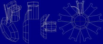
So, building: For the moment, I have a 12-sided, central, top cylinder, covered in the middle.
Now come the two outward slanting rocker covers. Let´s see if I can get the shapes more or
less right, and that the surface panels of the covers match with the cylinder panels.

Next will be the two pushrods, going down from the rocker covers on each side.
Then, the curved exhaust pipe slanting across the front, coming from the previous cylinder,
going down to the exhaust collector, a part merged with the shape of the engine block front.

Lets see...
Cheers,
Aleatorylamp
 
now, my friend, you're speaking my language.

i'm reminded of a long forgotten,
radial engine model i had as a kid.
this will be fun
 
Hello Smilo,
How nice! I suppose that model had transparent cylinders with moving pistons and valves - and perhaps it was even electrically driven?

Well, At the moment, I´ve got a front engine block, a top cylinder, a cylinderhead with two rocker covers, two pushrods, and one exhaust.

Cross-sections for pushrods and exhaust are square, and the cylinder base-triangles for the engine-block block aren´t done yet, and neither is the main lateral exhaust pipe.

Anyway, here´s a blueprint screenshot - just for you to inspect, whether it´s going acceptably well or radically not! I have included a profile line of the complete engine from the front view.

With 8 more cylinders 8 more cylinder-heads with 16 more rocker covers, 16 more pushrods and 8 more exhausts, the engine will have well over 450 parts.

I wonder...
Cheers,
Aleatorylamp
 

Attachments

  • topcyl.jpg
    topcyl.jpg
    56.2 KB · Views: 0
Hello Smilo,
...and a shot of the 1-cylinder putt-putt...

It looks like a fishing-boat engine without the main engine block!
There may be bleeds or cracks at the base of the rocker-boxes.

The shape is difficult to achieve, and it is very difficult to see if
it´s
bleeds or cracks, as the bottom surface of the rocker box
overlaps
the top of the cylinder at the front.
I think it´s bleeds, because on the blueprint it looks fine.

Have a look in your post, for the preliminary test-module.
Cheers,
Aleatorylamp
 

Attachments

  • topcyl-b.jpg
    topcyl-b.jpg
    3.7 KB · Views: 0
Last edited:
please, pardon me,
if i sit here with a wry smile.
i mean no harm or insult.
it's, merely, an observation.

i see a thread with 117 posts,
now, 118, most discussing
the engines, props and performance
of the aircraft in question.
(with a short tank diversion)

so, what's my point?
i chuckle to myself.
this is from a guy,
who has said,
ad2k construction techniques
are far too complex.

i guess it's all about what we like to do.

sorry...if i think it's funny.

research...nicely done, Stephan.

Hello Gentlemen,

I believe the reason there are so many posts covering the "uninteresting flight model stuff" is because the basic research was not done beforehand. Much of it was done DURING those 117 posts and by several people sharing information in this thread.
Note that at the beginning of this thread there was actually no idea what the correct performance of this aircraft really was.

Another factor that added to the number of posts is that the person doing the building isn't the one who really wants the aeroplane and needed to find out what would satisfy, and then that didn't quite line up with what the designer REALLY wanted to build.

Then, there were multiple attempts at explaining propeller tables and how they interact (when we were still guessing the Sensenich wooden propeller had 10 degrees pitch).

That may not be kind, but those are the highlights of what I remember....

Don't get annoyed, Smilo.
It is all part of the design process though usually it isn't done in this manner in a public forum.

- Ivan.
 
Hello Ivan, hello Smilo,
Well, I didn´t think the flight model stuff was so uninteresting, otherwise I wouldn´t have spent so much ink on it in the posts... but of course it depends on a person´s taste for it.
At the beginning it seemed quite straight forward, but quite soon it got more and more complicated because of the strange way the information was presented by the different sources.

After all if Ivan´s explanations on propellers, which I didn´t fully understand at the beginning, at the end, and BECAUSE of the posts in this public forum, most issues were clarified. So, the forum fulfills its purpose!

Some things are not too clear yet, and will probably stay unclear, because of the fact that many sources followed the FAA´s way of bundling everything up into normalized post-war HP standards. This way, the very probable over 200 units of 280 Hp stock Stearmans with a wooden propeller have been buried and forgotten about in the mists of time.

Also, the R-680-5 is most widely quoted as having 215 Hp, but a document stating engine certificates, shows is as equivalent to a -B5 with 240 Hp. I find that quite disconcerting. Maybe the -5 and the -B5 weren´t the same engine and that could be the mistake: There could have been a -5 with 5.5:1 compression, and a -B5 with 6.5:1. The early PT-13 production run of 26 units without letter had the R-680-5 series engine, without letter. So probably the 225 Hp is correct there, and a stock Stearman never had the -B5 = -5 engine with 240 Hp.

But who knows? ...and who cares? Even if I think it´s annoying that it´s so hard to find out for sure what´s correct, I know that complaining about it in a public forum is no use, but we are human, and humans err.

Anyway, we are trying to have fun, aren´t we all?
Cheers,
Aleatorylamp
 
well done, Stephan, thank you.
the package has been received
and a reply sent.

apparently, the Boeing Stearman Model 75
is still a valid trainer, even as a sim model.

as for the engine performance work;
even though it's not my cup of tea,
i've stated on more than one occasion,
how much i admire the attention to detail
and all the work being done.
it would seem, i need to state it again.

believe it or not,
i have read all the posts in this thread
and i did not find them uninteresting.
what i find annoying is the assumption
that i did.

post #118 was meant as a playful jab
at Stephan and Stephan alone.
an inside joke between him and myself.
it is all to clear, that the point was missed.
no thank you, Kwong, i will not be drawn
into a pointless quibble contest.
i have much more important things
in my life to worry about.
that's all i have to say about it.
other than, if you feel the need
to get in the last word...feel free
 
Flight Models

Hello Smilo,

I guess I am the local curmudgeon for now.
There was a lot of frustration to get to this point, but now I am fairly convinced that Aleatorylamp knows enough (or at least as much as I can help with) on this flight model.

With the last screenshot of engine models, I am pretty sure he found the same manual that I did though hopefully he saved a copy. I did not because it was a bit tedious to do so.
With the comment about -B5 engine versus -5 engine, I can see he has gotten to the same point with trying to match things up between military and company designations as I had though he has an incentive to find the real answer and I did not.

At the moment I am trying to understand some of the issues in working on yet another flight model for an older project and trying to do some tuning on two others to get them closer to release, so there is plenty to do which isn't really much fun at times.
Some of these technical papers I am reading using math that I haven't touched since High School and I am getting lost though I am getting a lot further than I did the last time I tried a couple years ago.
My Daughter has the math background but is off in College, so she can't help and would be too busy to help in any case.
My Son hasn't quite gotten to the classes he needs to understand the math yet though he might by next year.

My apologies Smilo. No wish to draw you into any kind of argument.

- Ivan.
 
Hello Ivan,
Yes, it took me many, many days to find the manual, and I could only make screenshots of the most interesting pages as it wouldn´t let me download it. I also found a couple of other documents, that seem to both confirm and refute some of the information!

Maybe they did this on purpose, just so some enemy would not get hold of any more exact info on this trainer, because it was so successfull that more than half of the 9000+ units built are still flying today!!


Thanks to your efforts in getting me to understand the mysteries of the propeller tables, I have been enjoying myself tremendously, trying out all sorts of different engines with the new fixed propeller, all with the same Boeing Stearman airframe.

So, with the information at hand, I was wondering what you would think about including the 5% extra power that the fixed prop was allowed to produce at full throttle. Thus, 100% throttle would really give 105% Power.

This would imply that the simmer would have to reduce to about 96% throttle for normal Vmax, and to 92% throttle for Vno. Not having a supercharger, the extra 5% can´t be done as WEP, in any of the 3 available types.

Normal Top Speed would be balanced for 124 and 125 mph for the 220 and 225 Hp engines.
Then, the short-spell absolute maximum for the 220 Hp engine would be 232 Hp, and the 225 Hp one would do 237 Hp. Speeds would be whatever the simulator should come up with at these powers.

Then, cruising speeds could be 95-103 mph and 100-108 mph for the two engines.
Would you think perhaps that possible Vno speeds (maximum continuous) could possibly be 119 and 121 mph?

Good luck with the maths on your two or three pending projects!

P.S.:
Incidentally, experimenting with my "pet 280Hp stock Stearman", I got the following results, which may explain the strange 135 mph top speed quoted by some sources:
100%: 280 Hp, 135.1 mph, 2283 RPM Vmax. (close to 2300 RPM)
_95%: 260 Hp, 131.7 mph, 2227 RPM Vno. (close to 2200 RPM)
Curiously enough, giving an extra 5% to this fixed prop engine, we get the 300 Hp the engine has when equipped with a CV propeller.
Another curious thing is that after the prototype stage, the Stearman-75 engine mount was strengthened to cater for engines of at least 300 Hp. Whyever would they have done this?
As it turns out, the engine-mount can cope with upto 600 horses!

Cheers,
Aleatorylamp
 
mild supercharger WEP effect

Hello Ivan,
Testing for WEP supercharger effects can be very tedious because it seems to take considerable time before it can be used after start-up. Supposedly it is because the engine has to warm up before it can be used in the first place.

To try out the 105% power option allowed by the engine factory-certification for fixed-pitch prop equipped R-680 radial engines, I experimented with a weak supercharger effect, that would hopefully ruin the engine if this short-time extra power is abused (even though this engine did not come with a supercharger).

So, regulating maximum engine performance to 225 Hp, and activating the supercharger option, with WEP Type as Supercharger, and entering 0.55 in the Boost Gain parameter, I got the 237 hp out of the 225 Hp engine/propeller setup.

I wonder if this would be good to use for simmers?

We had something similar for the Baltimore engines, but those really did have a supercharger.

Cheers,
Aleatorylamp
 
Hello Aleatorylamp,

What does the Operating Manual say about this?
You did see the performance graphs in the manual of course?
What EXACTLY are you trying to make happen in this case?
How is the 105% power gotten? What prevents its constant use? (I mean in the real aeroplane.)
I am asking about both the Actual Engine and your Virtual Engine.

Are you actually testing the power settings with a Fixed Pitch Propeller?
Use a Constant Speed Propeller for Engine Tuning!

I decided to get screenshots of all the pages of the Lycoming Operating Manual last night.
That was a little tedious but not too difficult.
Next, I just need to process them all which should be really easy except that some pages are skewed in the original.

Last night, Anna Honey got home from her business trip, so the house is not nearly as quiet today.

I have been working on testing the BV 141B and finished doing the first round of testing yesterday afternoon.
I say first round because I figured with all the work on Propellers I have been doing for your projects, I should at least do the same for what I am about to release and the idea is to alter the format of the Propeller Tables without altering the performance.
In doing this, I found a few interesting "Gotcha's" that I probably did not know about when the first version of the AIR file was created, so those need corrected first.

- Ivan.
 
Hello Ivan,
The answer to the questions are really quite simple. I actually thought that it was clear from what I´d already posted, but OK: The Stearman engines in question never had a supercharger, so the way the extra 5% was applied, was with the throttle lever´s final stretch of movement, the objective being, to get a little extra power for take-off and climb. If abused for too long it would ruin the engine, I suppose.

What would I want from it in the virtual model? Well, the 11 Hp difference gives a bit more nerve for climbing and 3.5 mph more level flight speed. Who wouldn´t want a little extra speed, even if only 3.5 mph? I can of course forget about it if it is just a nuisance and too small to be worth while.

I just thought the fact that it existed in reality was quite curious.

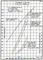
I had included an information paragraph from the manual, on this extra 5% engine speed, at the bottom of the engine/power table attached to post #117.

Perhaps the scanned small text is difficult to read, so here it is again:

"During normal operation of engines with a fixed pitch propeller, the rated engine speed should not be exceeded at any time. However, the Civil Aeronautics Authority permits a blade angle setting which would allow the engine to turn 105% of its rated speed IF the plane were flown at full throttle in level flight at sea level. This additional 5% above rated engine speed is permitted only with a fixed pitch propeller for the purpose of providing additional power during take-off and climb."

I have now attached a screenshot of the corresponding 225 rated Hp engine performance curve for fixed pitch propellers, which shows the necessary information graphically, and I don´t have any further data on the subject.

I am at present using the single 16-degree graph propeller tables for a fixed pitch propeller, and am adjusting aircraft performance with it. The results are coming out very well. A CV propeller would have quite a different performance and throw everything out of order.


Perhaps the extra 5% engine power is negligible and can be ignored.

Cheers,
Aleatorylamp
 

Attachments

  • Fixed pitch propeller plus 105.jpg
    Fixed pitch propeller plus 105.jpg
    49.7 KB · Views: 1
Power? What Power?

Hello Aleatorylamp,

I saw this page of graphs but did not look at it in detail because it was so small.
I have not been reading enough about this power combination to give any useful advice here.
I can think of a couple different approaches, but I don't want to send you off on a worthless pursuit.
A real solution will need a lot more thought and some experimentation (really to see what WON'T work).

- Ivan.
 
Hello Ivan,
I really don´t exactly understand what you mean, or the reasons behind your questions, I´m afraid.
It is only a question of deciding how to implement it and whether to do so at all. No complications of any kind!

The extra power is obtained by an extra RPM increase... how else? Both are reflected on the graph.

With the 16-degree (well, 15.95) propeller curves in the 2 propeller tables, the combination prop/motor with the engine torque and friction settings and aircraft Drag settings, are giving the 2 desired top speeds, at 2 power settings. The latter coincide with the graph, both the normal max. Hp and also the extra 5% Hp.

The 220 Hp Continental R-670-4 gives either 220 or 231 Hp and S.L. level speeds are either 124 or 126 mph
The 225 Hp Lycoming R-680-? gives either 225 or 237 Hp and S.L. speeds are 125 or 128.5 mph

The most logical thing to do would be to do it like on the real plane:
Full maximum throttle for take-off and at a given moment for power-climb, and if the pilot forgets to reduce it, he will ruin the engine. Great stuff! End of story!

Or, just put a stopper on the throttle lever and forget about the extra 5 percent, which must have been what the flying schools did, I suppose.

IF we want to use the extra 5%, we could be benevolent and include it in the normal throttle-lever-travel and the simmer wouldn´t be penalized by using it too much.
OR we could put it in as WEP and ruin his/her engine! I really see no complication other than having to decide how or whether to do it.

P.S. The extra momentary available 5% power is only mentioned on engine documents, and nowhere for the Stearman. Being a trainer, I am led to believe for engine protection reasons, it was not generally available in flying schools, except perhaps for specific aircraft where someone would have perhaps done something to an engine to access this little extra performance.
So, if everyone agrees and nobody is against it, mainly for the sake of simplicity, I will refrain from putting it into the Stearman 75 airfiles.

Cheers,
Aleatorylamp
 
Last edited:
Aleatorylamp said:
It is only a question of deciding how to implement it and whether to do so at all. No complications of any kind!

Hello Aleatorylamp,

If that is the case, then it is really just a design decision and you get to make the call, not me.

I just believe that no matter how you do this within the limitations of CFS, there are going to be side effects and you need to decide which side effects are most consistent with the choices an actual pilot would have to make.
With my own projects, I have made those decisions and designed accordingly.
With your project, it is just a little different because I don't know much about the operating limits of the aeroplane and it also happens to be a fixed pitch propeller which has other interesting effects.

One part of the CAA (predecessor to the FAA) note about 105% power has me a little confused because I do not find it to be consistent, but perhaps it really is. I really can't tell without trying to test out a prototype flight model and experimenting with a few parameters.

Now the following is just a bit of undirected rambling but perhaps these comments and questions will give you some idea of where I am going with this:
1. As the Pilot, do you use Full / Wide Open Throttle on the Take-Off Run?
2. This is a Normally Aspirated Engine. You simply CANNOT run too much manifold pressure.
3. What is dangerous and destructive to the engine? Excessive RPM: Sustained operation past 2100 RPM.
4. Is the AIR File RPM Limit really meaningful for a Fixed Pitch Propeller?
5. Can we really break the engine in the simulator? Probably not except for the 5:10 minute use of Supercharger.
6. The CAA authorizes this "105%" as allowed for Take-Off and Climb. What does this mean for a typical time limit?
7. What should the Engine Power versus RPM curve look like?

Hope this gives you some ideas.

- Ivan.
 
Hello Ivan,
The points you are making are very interesting, and have made me think a little further.

Looking into the Flight manual of the Navy Stearmans, there seems to be quite a difference in top performance capacity between the Continental and the Lycoming equipped types, as can be seen on the Power/RPM graphs at the end of the manual.

The Lycoming R-680 was later developed into a machine capable of 300 Hp at 2300 RPM, with mechanical improvements on cams, and with the addition of a supercharger, amongst other refinements.

The RPM and Hp graphs shown at the end of the Manual show readings going up to 2300 RPM and above, although some of it is quite difficult to read and to interpret (for me).

Consequently, it is quite debatable whether prolongued operation at 105% of the early versions would have ruined the engine! ...Most probably not.

100% was 2075 RPM on the first "letterless" R-680 Series, and although surpassing the 105% maximum of 2100 RPM was strongly recommended against, mechanically, 2100 RPM for any length of time would probably not have done any harm at all, even for more than 5 minutes!

The comments by the CAA as to its use seem only to have been cautionary measures. At the time when the engine was new, they didn´t know that it could be run faster and with more power.

I have read comments about pilots allegedly having dived at 300 mph without causing structural damage to either engine or airframe...

Consequently, and as there was no supercharger on the engine, it could be a good idea of simply incorporating the extra 5% - i.e. 237 Hp and 2100 RPM - into the normal maximum throttle lever travel, to be used for Take-off and Climb, as would be normal on any other aircraft. Nobody uses full throttle all the time anyway!

I know it´s my call to put in whatever I want into the .air file... but I´m trying to be realistic.
On one hand, just to be safe, I could limit performance to the CAA recommendations, for a flying school, as it were, or I could be more realistic and adventurous, and incorporate the 105% into the normal use of the engine. The more I think about it now, the more the latter seems the best idea.

Cheers,
Aleatorylamp
 
Last edited:
Hello Aleatorylamp,

First of all, WHICH Engine are you trying to simulate?
It is hard to keep things straight when you keep changing the subject within a single post.
If you want some input from me, you have to keep in mind that I have not done as much reading on the Stearman or the Lycoming R-680 as you have and probably never will. *I* am not building such a project.

Now with that in mind, the Graph you posted from the Operating Guide was for a R-680-B4 as can be seen on the Label at top center.

The engine you are describing would be making 237 HP at 2100 RPM.
The R-680-B4 according to the graph:
at 100% power (2100 RPM) is making 225 HP
at 105% power (2200 RPM) is making 237 HP
That isn't far off but it isn't the same either.

I also believe you are rationalizing to arrive at the conclusion that there are no real operating limits to this engine and that the CAA simply didn't know.
Later engines had more power and capability but they were not simply running the same old engine at a higher RPM.

As for reasons why operating limits are established below where the engine may run without failure, there could be many reasons:
The heat rejection of the cooling system may not be sufficient to run a particular power setting continuously.
There may be a greater likelihood of actual failure during use.
There may be an additional service requirement after WEP use.
Emergency power may reduce the Time Between Overhauls below the manufacturer's guarantee.

- Ivan.
 
Hello, Ivan,
Yes, I understand. The problem is I can only find the graph for the -B4, an engine similar to the one I´m trying to install, which was the R-680-5 (no letter). For the R-680 "no letter" series there is only a graph for the basic one with 215 Hp available, which is not what I want.

I also understand that all the refinements for more powerful engines of the same type developed later, meant they could be run at higher speeds for more time than the earlier types.

Hence my doubts and suppositions of trying to deduce how the engine I want would have worked, but apparently it is a futile exercise, and because of the lack of specific information for the engine, it will probably be best to forget about it and just go for the Navy Version´s newer -B4.

Update:
the normal-powered Stearman-75´s I´m interested in are all WWII ones. I would suppose that the -B4 would be OK for that time, as the Navy Stearman Manual was published in 1941. So instead of making an early Stearman 1937 or so, with a R-680-5 (no letter) engine, I could make a 1941 one with the R-680-B4.
No problem.

OK, then. Thanks for your comments!

P.S. I have the feeling that this is getting a bit too complicated, and is creating more bother than benefit. I´m sorry if this has got annoying for you, but that´s why I had suggested a short time ago to forget about it.

I think it is not worth while delving into it much further, for the marginal effect it is going to have on the virtual model´s behaviour anyway.

On the other hand, your comment that what I was trying to achieve could already be quite close, is actually really quite satisfying, given the difficulty in obtaining any better information on the early series of engine I´m trying to put in.

Thanks again!
Cheers,

Aleatorylamp
 
Last edited:
Aleatorylamp said:
The problem is I can only find the graph for the -B4, an engine similar to the one I´m trying to install, which was the R-680-5 (no letter). For the R-680 "no letter" series there is only a graph for the basic one with 215 Hp available, which is not what I want.

Hello Aleatorylamp,

I believe you are really not understanding the designation system here.
Have you found even ONE military designation that has a prefix letter in it?
As an illustration:
The military called the Continental radial engine the R-670.
The Continental company designation for the same engine was W-670.
The Wright R-1820 engine was used in the B-17, F4F, FM-2, Brewster Buffalo, Curtiss-Wright CW-21, etc.
If the military used it, it had a designation looking like R-1820-SomeNumber.
If it wasn't a military contract, it may have been a simple R-1820-Something OR perhaps a GR-1820-Something.
Company designations used a G prefix if it was a reduction geared engine and no prefix if it was direct drive.
The military never had a G prefix on their models.
There should be a company designation for every military version but it isn't likely to be the same.
Thus your R-680-5 corresponds to some Lycoming R-680 series of engine (I am guessing this is a B series engine).

I am not sure which one matches.
I already hinted at this situation back at Post #42 back on August 15 when I first found the manual you are looking at right now.

-------

It also sounds to me like you are giving up on trying to figure out how this engine should work.
Important thing here is NEVER GIVE UP!
Get it wrong perhaps. Put it on hold until you figure things out, but NEVER GIVE UP!

As I see it, (and I may be wrong because I haven't actually worked on it), the problem you have here is actually very simple to solve. I have been trying to hint at the process without just telling you outright because I thought it would be more meaningful if you figured it out on your own.

First of all, tune your Engine power curves using a Constant Speed Propeller. (Sound Familiar?)

Tuning the Engine:
Plot Horsepower versus RPM. (You already have such a graph in the manual, but you want to make your Engine match it.
Here are some numbers without checking the references, so you will need to check them yourself.
Continuous operation appears to be 1900 RPM giving 202 HP at FULL THROTTLE
Set your test Engine's down to 1900 RPM at FULL THROTTLE and see what the output is. Adjust if needed.
Normal Maximum appears to be 2100 RPM giving 225 HP at FULL THROTTLE
Set your test Engine's down to 2100 RPM at FULL THROTTLE and see what the output is. Adjust if needed.
Absolute Maximum appears to be 2200 RPM giving 237 HP at FULL THROTTLE
Set your test Engine's down to 2200 RPM at FULL THROTTLE and see what the output is. Adjust if needed.

I am thinking your question right now is:
Hey! Wait a minute, what SHOULD the RPM limit be???
Answer: It really doesn't matter because we are tuning the Engine's Torque and Friction curves and you will find that when you finally plug in the fixed pitch propeller, the RPM limit is pretty much meaningless anyway though I still think you should set it to something like 2200 RPM in the final version to make things look right.

Now if you want to control the power with an over speeding propeller, you MIGHT want to tune the Torque or Friction way high above 2200 RPM to discourage High RPM operation. Your call on this one, but I would do it.

Tuning the Propeller:
With your neat nifty Wooden Propeller in place. (Set to Fixed Pitch with proper Angle.)
Adjust your AIR file so that the Aeroplane simply will not move. (This is an Engine / Propeller Bench Test, so bolt it down!)
Put in some Concrete Spoilers, or whatever.
Run your Engine at FULL THROTTLE.
Note the RPM.
Compare the RPM to the specifications in the FAA Type Certification document.
(I TOLD YOU that document was useful!)
Adjust Propeller Power Coefficient in Table 512 until you get proper RPM.
Adjust the rest of the Power Coefficient curve (singular) in Table 512 until you get something looking like other Power Coefficient curves of which you have many examples.
Note that the important parts are basically the two ends at J=0 and where Efficiency drops to Zero.
The rest can be a straight line or slight curve: Your choice.

When you are finished, Remove the Concrete Spoilers and Unbolt the Aeroplane so that it can actually fly again.

Now here comes the really fun part you were agonizing over:
Keep in mind that I am a 1G pilot with no experience on a Stearman, so beware.
As the new owner of this Stearman, the Pilot should read the manual and limitations (Checklist).
It would say something like Blah Blah, Don't exceed normal maximum 2100 RPM for routine flight.
2200 RPM authorized for Take-Off and Climb only.
Vne 186 MPH..... Blah Blah.

Pilot straps in, says his prayers and starts and warms up the engine.
She taxis to the runway and then what?
Does she use FULL THROTTLE on the Take-Off run?
Yes, because this is a naturally aspirated engine and this is one BIG cotton ball with not a lot of engine power.
(Real aeroplane owners are probably hating me right now,)
Is there any danger of exceeding 2200 RPM?
Probably not because the aeroplane is pretty slow on Take-Off and there is a lot of drag on the propeller (Power Coefficient table).
You will have to confirm whether what I am telling you is true or not. I have NOT built this flight model yet.
Just do not exceed 2200 RPM, but by the time that even gets close, the aeroplane should be off the ground and climbing.
So do we reduce power from FULL THROTTLE in the climb?
Probably not because climb speed is so far below maximum that there should be enough propeller drag to keep RPM below 2200.

Besides, if you look at other manuals, the Climb power setting is typically authorized for 30 minutes or so.

Once settled in level flight after the climb is when FULL THROTTLE may not be appropriate.
Here it is a balance of speed and propeller resistance to see what the actual throttle setting should be to get down to 2100 RPM or 1900 RPM or whatever the Continuous Operation limits are.

You will need to experiment here. I can't predict how things will stack up.

Hope that makes sense.
I wish the Propeller issue I am having with my BV 141B were this easy to resolve.

- Ivan.
 
Hello Ivan,
I wasn´t really going to give up yet.
I just thought it was getting too complicated to continue discussing on the thread. Anyway, thank you for your indications. It will take some time to follow, but it already sounds familiar.

For the Continental R-670 series it is all much simpler, including the military designations. These and the types were by far not as complicated as for the Lycoming R-680 series engines.

According to Textron Lycoming, AVCO Corporation, the engines that were produced of the R-680 series were the following: (noteworthy is that the -4 and -5, and the -B5 and -B4 are not the same engine!)

R-680, R-680-2, R-680-4, R-680-5, R-680-6,
R-680-B2, R-680-B4 Series, R-680-B5, R-680-B6, R-680-BA,
R-680-D5, R-680-D6,
R-680-E1, R-680-E2, R-680-E3, R-680-E3A, R-680-E3B

Sticking to my earlier "no letter -5" for a moment, right now, I have the RPM difference for the 225-237 Hp difference much lower than 100 RPM, actually at best only 39 RPM (2163-2202 RPM). This difference would actually more or less fit what I had deduced for a "no letter" -4 or -5, i.e. 2075-2100 RPM.

I started out from the point that the basic R-680 (no number or letter) gave 215 Hp at 2000 RPM, and tested for a 10 rated Hp more powerful engine in the sim. I supposed that normal max. 225 Hp for the -5 engine would be correct at 2075 RPM, and that at 2100 RPM, the full max. 237 Hp would also be correct. Less sharp cam angles, giving lower RPM than the -B4, etc. Then, gas consumption flat out is at a very high 18 Gal/hour... perhaps OK for the older, more inefficient version, which is being squeezed out for more power.

Anyway, I expect that your detailed instruction for a more correct tuning procedure, will lead to the results that are more fitting to the graph of the newer -B4 series - giving a 100 RPM difference between the 225 and 237 Hp - as for this engine we DO have exact details - not so for the "no letter" -5 version.

Thanks again!
Cheers,
Aleatorylamp
 
Last edited:
Back
Top