Boeing Stearman Model 75

Hello Smilo,

I try to go as far as I can to the point where I can't shoot any more holes in my process..... or run out of knowledge of how to address the issue in question.
Then I go do a bit of reading.
Sometimes it takes a long time before I figure out what to do.
The Propeller Tables took about two years from start to finish though there were a lot of intervening projects.
The problem is that with this cycle and the general boredom factor, not a lot gets "finished" in my workshop and it seems a lot more like work than a hobby at times.


Hello Aleatorylamp,

The process that I was suggesting was not to compare acceleration times but rather to pause and record the HP and Thrust values at the same speeds during the Take-Off run.
Then do a comparison between the numbers you get for each pitch value and see if they appear reasonable.
If I am correct, you will understand what I have been trying to tell you.

- Ivan.
 
Hello Ivan,
Yes, I finally realized that... uuffff... I just had a two-day headache :unconscious:before having to make my daughter´s lemon-merengue pie and the extra pallet furniture for the patio, so neither my brain nor my attention have been up to par until a few hours ago.

Then, I updated my previous post with the results of the test that I finally did as you suggested.

I wonder if the results - i.e. absolutely no difference in Hp, Thrust or RPM between 10 and 15 degree pitches - are valid, have any meaning, or need any corrective measures...
You asked if the results seem reasonable to me... well... I don´t know...
It felt OK, though, on the plane, in BOTH cases... Here are the numbers:

mph__Hp___Thr
_15 - 178 - 771
_30 - 196 - 604
_45 - 200 - 520
_60 - 200 - 495
_75 - 202 - 471
_90 - 209 - 464
105 - 216 - 455
120 - 224 - 439

Hello Smilo,
Congrats on your progress with the detailed L10 landing gear, I´ll be glad to see it!
We do, the three of us, have our ways with complicating things, don´t we?:teapot: Cup of tea?

Just for eye-candy, here are the propeller tables of the new shiny varnished wooden 10-degree pitch propeller.

Cheers,
Aleatorylamp
 
Hello Aleatorylamp,

This is what I have been trying to tell you for a very long time:
You NEED a 10 degree graph in your propeller tables.
Without such a graph, the lowest value graph is 15 degrees (which is why I picked 15 degrees for the test).

So.... What you are really doing for ANYTHING under 15 degrees is using the 15 degree graphs.
That is why the numbers are exactly the same for 10 degrees and 15 degrees.
It is not so important in the Power Coefficient Graph (Table 512) but fairly crucial in the Propeller Efficiency Graph.

This is why I said your testing was pretty much meaningless until you had reasonable Propeller Graphs.

- Ivan.
 
...but it works!

Hello Ivan,
OK, you said 3 days ago that I would need a graph for 10 degrees, but you also mentioned that the computer interpolates.

This means, as you also say, that the sim uses whatever values it finds in the 15 degree graph for a 10 degree pitch, which would be correct anyway, as shown by the results.

I doubt that performance will change by moving the present 15-degree graph to the 10-degree position, but of course, I could be mistaken.

That´s why I didn´t understand why you repeated that the test was meaningless. I knew it was meaningless, but for a different reason - it had all the old graphs. The point I was making, as I said, was that it was the first time I had managed to get a fixed pitch propeller reflected on the Beckwith gauge.

Changing the graph is easily done, so I´ll try it anyway, just in case I´m wrong and something does change.

Whoa!
Changing the graph to a 10 degree position is more easily said than done.
For the moment, it won´t budge, even exporting the table as a txt file, changing it and importing it again.
There is a decimal comma error - I use decimal points. I´ll have to change the computer settings and see if it works.

Whoa-2!
Changing the decimal point to a comma in the exported text file won´t work either.
Editing the label from 15 degrees to 10, is not allowed, neither in AAM nor in AirEd, and FDE won´t show the graphs, as you know.
We seem to be landed with the 15 degree graph that gives the sim the reading for its virtual 10-degree graph.
So then, if the values for 10 degrees are entered in the 15-degree column, so what? It works anyway.
If it works, why fix it?

Now, seriously... do you know of a way to move the graph, or make an extra one?
I remember you were using a binary or Hexadecimal editor to make alterations to these tables. Maybe that will be the only way - even if only to make sure that performance will or won´t get better...


Cheers,

Aleatorylamp
 
Last edited:
Propeller Tables Again

Hello Aleatorylamp,

Aleatorylamp said:
OK, you said 3 days ago that I would need a graph for 10 degrees, but you also mentioned that the computer interpolates.

I made the suggestion about a new propeller table back at Post #48 on August 16, so it has been a little longer than 3 days.
The reason I suggested 5 degrees to 20 degrees back then was because I saw that the pitch ranges got down as low as 7 degrees and you need a low and a high value so that the simulator can interpolate between them.
The idea for 25 degrees was because of the number of graphs typically found in a propeller table gives more room.

Right now, the simulator is trying to interpolate between the 15 degree graph and the one below it and there isn't one below 15 degrees.... so it uses 15 degrees.

It sounds like I really should do a Propeller Tutorial at some point. This subject keeps coming up.

Aleatorylamp said:
I doubt that performance will change by moving the present 15-degree graph to the 10-degree position, but of course, I could be mistaken.

That´s why I didn´t understand why you repeated that the test was meaningless. I knew it was meaningless, but for a different reason - it had all the old graphs. The point I was making, as I said, was that it was the first time I had managed to get a fixed pitch propeller reflected on the Beckwith gauge.

Changing the graph is easily done, so I´ll try it anyway, just in case I´m wrong and something does change.

If you just rename the 15 degree graph, nothing will change.

If your 10 degree graph really goes to Zero efficiency at 0.8 Advance Ratio as I believe it should for geometric reasons, then I believe it will SERIOUSLY affect your performance numbers.
To figure out how I got this number, do a calculation for the Angle of Attack for a Blade Element at 75% radius and then at 100% radius with a pitch of 10 degrees. I believe the actual value somewhere between those two values.

The interesting thing here is that although your maximum speed will be more limited, your low speed handling will greatly improve as will your climb rate. ....AND you will notice some serious differences in handling if you put in your much discussed 280 HP engine.

Regarding Whoa!!
I believe I already sent you my Record Extract Program when you were working on Fuel Tanks.
I also wrote Record Decode and Encode Programs but you really don't need those.
In fact, you don't need the Record Extract Program either.

Jerry Beckwith has a utility called AirDump that will do much more than my programs will.
The reason I wrote my own versions is because I wanted command line utilities (I like those) for very fast cycle times and because I wanted more significant digits in the spreadsheet.
For quick test cycles, I could literally make a small edit in a Propeller Table and replace the record in the AIR file in about the same amount of time as it took for the simulator to shut down and restart.

The high precision floating point numbers were not important for my Ki 61 but they were quite useful when fine tuning the propeller tables for your Focke Wulf 200 Condor.
The Low to High Pitch change needs a very very small difference in values in the Power Coefficient Table.
I could have made it happen even quicker but did not want to hide things from you because if I had made the values close enough, the normal tools you have available would not be able to see the difference... Unless you want to start pulling apart the record in a Hex Editor.

- Ivan.
 
Hello Ivan,
I´m sorry to say I didn´t understand what you were trying to say in your Post #48, apart from having to tune propeller tables anyway, as typical pitch angles run from 7 to 13 degrees, and thus, stock tables won´t work all that well.

From this, I didn´t understand the need to create a 10 degree column - the computer uses the lowest available 15 degree one anyway, because it can´t interpolate, so the 15 degree column is in effect the 10 degree column. Remember it is only reading for a fixed pitch propeller, and doesn´t need another column.

Anyway, thank you for your suggestion or better said, reminder about using AirUpdate. Sorry it had slipped my mind. It worked perfectly well. Wonderful! There are so many details you have mentioned in the past, and I just can´t remember all of them. Sorry again...

So, I changed the label for the 15 degree to 10 degrees both tables, and it took less than half a minute! Excellent! Thanks a lot.


Well, the result of all this is what I had unfortunately already expected, I am sorry to say.
The computer is reading that same column now for 10 degrees, and the aircraft is behaving in exactly the same way. The Hp, Thrust and RPM readings for every 15 mph speed increase is reading the same as before.
What else can I say?

Cheers,
Aleatorylamp
 
Hello Aleatorylamp,

No worries about understanding things the first time out.
It takes me a few tries to get things too, and I can't even blame it on old age because it has been true as far back as I can remember. There are at least a half dozen things I can't make progress on because I can't figure them out, not to mention getting distracted by any new thing that comes along.
The difference is that I also don't have a mean *** trying to explain how things work! ;^)

Now that you found that just renaming things does pretty much nothing as I warned you about earlier, here is what I believe you should do:

Use AirDump / AirUpdate to get a text / CSV version of your Propeller TableS. Yes, Both of them!
Delete the 55 degree angle row.
Add a new 10 degree angle row that this the same as the 15 degree row.
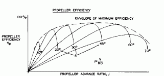
If you are working with my version of the Propeller Efficiency Table where he efficiency drops to Zero,
then set the efficiency for J=0.8 to Zero for the 10 degree graph.

Since it is a CSV file, you should have no trouble bringing it up in a spreadsheet.
Bring it up and graph it so you can have a visual image of how your graphs relate to each other.
For 10 degrees:
Figure that your limitations are that Efficiency at J=0.0 is going to be slightly higher than for 15 degrees.
Figure that for geometric reasons, Efficiency becomes 0% at J=0.8.
Decide what the Maximum Efficiency for this curve should be; Somewhere between 50% and 60% sounds reasonable.
Adjust the other points so that the curve looks the way you want.

Fly it.
Fine Tune it.

Use the curves I posted earlier to get a feel for what the final result should look like.

- Ivan.
 

Attachments

  • PropPerf01.gif
    PropPerf01.gif
    4.3 KB · Views: 0
Hello Ivan,
Thank you for your explanations, but I understand that basically, I might as well be working on the 15 degree graph, for all the computer is going to read. But OK, I have made 10 degree graphs, for table 511 and 512.

The efficiency graph is a modification of the drops-down-to-zero one that you made for the 2-pitch FW200 propeller. The other one is a modified stock one where I pushed up the low angles a bit, more finely fitting the lowest one.

I had already adjusted these graphs before, as 15 degree graphs, but which the computer used as if they were 10 degree ones. With this, I achieved maximum S.L. level performance I wanted. Now it is a 10-degree graph, and behaviour is the same.

OK, the only difference from what you are suggesting now is that the curve should go down to zero at advance =0.8, not 1.0 as it does now.

I will adjust that accordingly! Thanks for the information.

Then, you suggest that I can finely adjust low speed performance, which will also affect RoC, should this be deficient. Very well! RoC is something I hadn´t tested yet.

Advance - True Air Speed

0.0----------0 MPH
0.2----------39
0.4----------78
0.6----------117
0.8----------156
1.0----------195 MPH

I realize that I can finely adjust different places corresponding to different speeds.

Here are screenshots of my two graphs, where I´ve written in the values.

The only other thing that strikes me is that I could raise the point for J=0.2 in the efficiency graph.

I don´t think I understand why there should be a 15 degree column if I´m not going to use it, other than for comparison purposes.

By the way, I don´t use spreadsheets, so I just made AAM screenshots and wrote in the values.

Thanks for your indications!
Cheers,
Aleatorylamp
 
Hello Ivan,
OK... Quite amazing... My understanding on the method and reasoning (Descartes??) of propeller tables is taking shape (I think...), and more than one mystery is becoming unveiled. Thank you very much!

I clipped the J=0.8 part of the efficiency graph doen to zero, increased the 0.2 and 0.4 a little, and pulled down J=0.6 to 0.6, which above 60%, following your 50-60% recommendation.

Of course, RoC improved, and top speed went down a little, so now I´ll adjust the other table.
Updated note: Here I´ll probably need an extra column for J=7, to get a bulge that will soften the abrupt drop. At the moment I can´t get upto 120 mph without exceeding both Hp and RPM.

Naturally, if I expected this propeller to be of any use above 150 mph, I´d be wrong.
This would be the main point you were making. I just coudn´t get it.
I deduce that here I would need a higher pitch one, say 13 or 15 degrees, with J=8 peaking at 60% and J=1.0 dropping down to zero.

For the probable military 280 Hp PT-13B, however, the propeller would still be within limits, as I am supposing that the 135 mph top speed would refer to this aircraft.

Of course one could make the graph shape more realistic by moving several of the unused higher pitch columns to the left, to make the transition of the J factors 1 instead of 2.
This could actually be quite appetizing.

Then, for a CV propeller, of course the creation of a 15 degree column will be mandatory, and the adjusting work on the tables will be multiplied by whatever numbers of columns were to be used!

Fine! Hmmmmm... Very nice! :icon29:
Cheers,
Aleatorylamp
 
Last edited:
Hello Ivan,
I´m having trouble balancing power/performance to get S.L. max. performance after
curbing the 10-degree propeller´s efficiency to 60%. Are you sure this is correct?
I have a graph that would indicate a possible maximum of 65-70%.
Originally I had about 67%.
Can´t this be used, in your opinion?
Cheers,
Aleatorylamp
 
Ivan's Propeller Shop

Hello Aleatorylamp,

I am glad you are finally understanding what I have been trying to tell you.
Next trick is to keep in mind how computers work and the limitations on this method of modelling.

Aleatorylamp said:
At the moment I can´t get upto 120 mph without exceeding both Hp and RPM.

I believe you have a different problem here.
There are a LOT of other factors that will need to be corrected once you have the propeller graphs "In the Ballpark".
That was why I was telling you that you needed to get SOME KIND of propeller graph in place first or you were just wasting your time with tuning.

Just by changing the PT-13B/C to 280 HP will probably not affect things by more than a couple MPH at best; I do not believe you will get 135 MPH by doing just that.
Your Engine (even the 225 HP version) also needs a bit of tuning to fit the new propeller.

Aleatorylamp said:
Of course one could make the graph shape more realistic by moving several of the unused higher pitch columns to the left, to make the transition of the J factors 1 instead of 2.
This could actually be quite appetizing.

It is actually Advance Ratio and not Pitch that you are trying to compress.

Actually I had already been thinking about that back at Post #87 almost a week ago when I was calculating how fast the aeroplane was going at each Advance Ratio.
I noted that the entire operating range was from J=0.0 to J=1.0 and could not exceed J=1.0 even in a power dive.
Then again, at a lower RPM..... Same speed means higher Advance Ratio, so you need to do a few quick tests / calculations to confirm that will not be an issue.

Building a Propeller Graph is easy. To do it right is a bit tougher than it looks.
First of all, for an Advance Ratio increment of 0.1 instead of 0.2, you would need to recalculate where Efficiency drops to zero at each Pitch Angle.
I had thought about recommending that as an approach, but thought it was way too big of a can of worms to handle.

Aleatorylamp said:
I´m having trouble balancing power/performance to get S.L. max. performance after
curbing the 10-degree propeller´s efficiency to 60%. Are you sure this is correct?
I have a graph that would indicate a possible maximum of 65-70%.
Originally I had about 67%.
Can´t this be used, in your opinion?


Sir, you do NOT have such a graph. Or should I say: What you just posted is not such a graph.
Your posted graph only goes down to 15 degrees.
You need to find one that goes down to 10 degrees.

Adjust the efficiencies however you see fit.
The stock AIR file have efficiencies that are on the high side.
Even my Ki 61 Propeller Efficiency is a touch high because it was supposed to duplicate the original stock AIR file in general performance.
I did not want to change too many things at once because then, one has no idea if there is a problem where the cause is.

At this point You are more of an expert with Propeller Graphs than I am.
You seem to understand how the graphs interact and know how to tune them.
The rest of it is really just doing the research for real world data to put into the graphs.

I haven't even released ONE project with a proper set of Propeller Graphs yet and you have.
In fact, my current BV 141B-0 will almost certainly have a set of stock propeller graphs on it re-release.
Perhaps it will get a new propeller at some later date.

- Ivan.
 
Hello Ivan,
Thanks for your comments and recommendations. Sorry! I tend to confuse terminology I´m afraid, but I´m glad you understood what I meant. I´ll leave the intervals at 2 then, and leave the can of worms for the fish and the birds!

I did see that the table I posted has no 10-degree graph, but I was suggesting that a 10-degree graph could be inferred. Obviously it wasn´t as obvious as I thought - I should have drawn in an additional red graph line.

The interval would be calculated at the bottom, as what would follow from the sequence starting on the rightmost graph. It gets progressively smaller as you move left, and the 10-degree graph would then be incorporated at the resulting distance to the left of the 15-degree graph bottom.

Its top curve would start a bit lower and to the left of the 15-degree curve, its beginning flush with the main outside arc. I had the feeling I could see a non-existing 10-degree graph with its peak around 67%...

Another way would be to have a 11.7 Degree graph, for a 11.7 degree pitch propeller - the maximum on the certificate, to allow a higher peak.

OK, let´s see how I manage.
Cheers,
Aleatorylamp
 
Hello Aleatorylamp,

Perhaps you SHOULD try to work on a graph with Advance Ratio intervals of 0.1.
I tend to aim for perfection but sometimes you have to be satisfied with incremental improvements.
Even if it is not perfectly accurate, it will be more correct than the stock Propeller Tables and I don't see too many complaints about those.

If you want to play around a bit, you might want to download Jerry Beckwith's AirWrench.
(The name always brings the image of an Air-Powered Impact Wrench to my mind.)
It generates its own propeller tables as well.
....and No, the intervals do not need to be spaced evenly.

Aleatorylamp said:
I did see that the table I posted has no 10-degree graph, but I was suggesting that a 10-degree graph could be inferred. Obviously it wasn´t as obvious as I thought - I should have drawn in an additional red graph line.

You inferred 65-70% efficiency in the imaginary graph that I did not see and I was using an actual graph that showed more like 53% that I could see.
Why should it be a surprise that we did not arrive at the same conclusion?

- Ivan.
 
Sensenich Wooden Fixed Pitch Propeller

Hello Ivan,
My life with the 15 degree pitch propeller was easier.
The 10 or 11.7 degree propeller is not doing very well at all, I must say!

It´s certainly a pity that the FAA certificate doesn´t give the pitch for the wooden fixed prop.
But what if it does?

IT DOES!

It quotes 98AA66, 98AA64, and 98AA66 propellers for the 220-225 Hp Lycoming radial engine.
The first number is the propeller length in inches.
The second number is the pitch in inches, (theoretical advance, supposedly no-slip).

Looking at the Sensenich Propeller Certificate List, these propeller reference numbers are found preceded by the letter "W". I found a converter to convert pitch inches to degree-angles at 75% prop radius.

W98AA66 standard prop. 66 inches pitch = 15.95 degrees.
W98AA64 climbing prop. 64 inches pitch = 15.49 degrees.
W98AA68 cruising prop. 68 inches pitch = 16.41 degrees.

The reference to the 9 to 11.7 degrees for the other propeller must mean a ground-adjustable propeller, where the blade angle can be varied between 9 and 11.7 degrees. This does not mean pitch angle. I understand that these two terms exist and do not necessarily mean the same thing.

So, in view of this new data, I suppose can proceed with a greater degree of success.

I may make tables with advance intervals of 1 instead of 2, but perhaps it will not be needed other than to round off the down slope a bit on the efficiency graph.

Thanks for your indication on the 53% efficiency for a 10 degree pitch prop, but I suppose that it will not be applicable any llonger.

Cheers
Aleatorylamp
 
Hello Aleatorylamp,

Now that find IS interesting!
That explains why there is no associated pitch data in the Type Certificate.

Glad you got what you needed.

As I stated when I proposed 10 degrees for pitch, I was guessing based on what I was seeing in the Type Certificate and if you had actual data to go with it.

Congratulations.

- Ivan.
 
Hello Ivan,
Thanks! At least that has finally been cleared. I knew there had to be some more information hidden somewhere!
Now I´ll check the QBasic program I wrote with the propeller formulae, to find out where a 98 inch, 16 pitch propeller efficiency graph should drop to zero. Maybe at J=8.5, or 8.6, perhaps, judging from the picture of the graphs starting at 15 degrees and going up to 45.

Cheers,
Aleatorylamp
 
Last edited:
A Question of Performance

Hello Smilo, Hello Ivan,
As we know, there is an appreciable degree of inaccuracy regarding the performance of the different Stearman-75 motorizations, as shown by the inconsistencies between speeds and engine power already mentioned.

Once we sift through the usual contradictions and confusions in the different sources as to which engines were used on which models, we still have to decypher the different references for the engines used.

If we look at the different early Lycoming R-680 types that were used on the PT-13 models, it appears that they have generally all been bundled into the 225 Hp category because of FAA Certification, but the FAA didn´t exist at the time.

What did exist though, were factory certificates that shed quite a different light on the performance of the different engines. Not only is there evidence for the 280 Hp powered P-13B´s, but also for some 240 Hp powered PT-13´s. Also, it seems that engines with fixed pitch propellers were allowed a 105% power for take-off and climb for short periods.

The 240 Hp powered version could well have had Vno of 125 mph at 225 Hp... and Vmax at 130 mph.

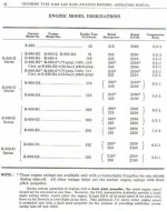
I have attached a picture of the performances and equivalences of the different R-680 Lycomings.

It also appears that after the first three early R-680 types, which were made for fixed pitch propellers ONLY, the rest were made for CV props, but all with provision for fixed props AS WELL, involving lower Hp and corresponding certification changes, as engines were essentially the same, but without the CV performance.

There is an added inconvenience caused by the different way the factory, the army,and the navy went about their engine nomenclature. For the reference numbers R-680-7, -8 and -11, it is difficult to pinpoint which factory model they correspond to, but others, like the R-680-4 and -5 have equivalences that clearly show a substantial difference in power.

On the other hand, the Continental R-670-4 and -5 on the PT-17, offers no doubts: Both 220 Hp engines conferred 124 mph to this plane. Certifications for the W670-6A and -6N which were used, mention a rated 220 Hp at 2075 RPM for take-off, 1750 for cruise and 1890 for max. cruise. It appears that higher powered variants were not used on the PT-17.

Let´s see if it is possible to decide what to go for.
The Continental-powered 220 Hp military version, would be no problem...

More later...
Cheers,
Aleatorylamp
 

Attachments

  • Lycoming Engines.jpg
    Lycoming Engines.jpg
    62.6 KB · Views: 0
Last edited:
please, pardon me,
if i sit here with a wry smile.
i mean no harm or insult.
it's, merely, an observation.

i see a thread with 117 posts,
now, 118, most discussing
the engines, props and performance
of the aircraft in question.
(with a short tank diversion)

so, what's my point?
i chuckle to myself.
this is from a guy,
who has said,
ad2k construction techniques
are far too complex.

i guess it's all about what we like to do.

sorry...if i think it's funny.

research...nicely done, Stephan.
 
Hello Smilo,
I know... and I understand exactly what you mean. Thanks for the push! It´s getting a bit heavy, too much of the same thing - it is the eternal problem modellers are faced with, to find and collect enough reliable information so that the flight model comes out as good as possible.

The thing is that it bothers me to have this uncertainty as far as performance is concerned, not to know exactly what to put in the .air file. The contradictions and lack of correct and/or complete information gives rise to unanswered questions that just nag in the back of the mind... very bothersome indeed!

On the other hand, one very satisfying point after all this research, is that the propeller pitch question is solved, and that the standard performance for the normal 220-225 Hp motorizations is also sorted out.

So... it shouldn´t really bother me any further, should it?

I mean, why don´t I just go ahead and start building the darn thing?!
Exactly! Thank you! So that is now just what I´ll do!

Well, the first thing I´ll do is to make the 12 o´clock cylinder as described previously, and send it to you!
Cheers,
Aleatorylamp
 
my comment was merely an observation
and not meant to be criticism or even a nudge.

i admire your tenacity and diligence
when it comes to flight dynamics.
it's something, i've never had the patience for.
but, then again, this is coming from a person
who has spent the last week or so
trying to build the main gear for the L10.

as i've said, many a time,
we each have our own interests specialties.
 
Back
Top