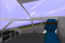
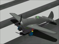
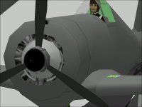
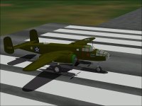
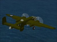
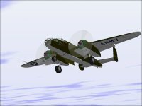
CFS1 Curtiss-Wright AT-9 "Jeep" Work In Progress.

Hello Aleatorylamp,

I got your email and I believe I have eliminated the bleeds of the Seat Backs.
The bleed from the bottom through the Wing Fillet is gone as you described.

I will do the SCASM process in a couple hours. I am actually fairly certain that you do not understand what I was describing in my prior post. When you see it, it will become obvious what I meant.

The following is an explanation of the quick email I sent you very late last night when you ran into a problem with adding the SCX for the Canopy Frame.

Consider how odd this conversation was
You told me that you were unable to add the Canopy Frame because it would not fit into the MDL file.
You said that you wanted to add Seat Backs but would probably need to delete a few things until the Canopy Frame fit.

I told you: DO NOT DELETE ANYTHING! Add your Seat Backs and it will probably fix things.
(Instructions to make something BIGGER is a strange thing to recommend when you are running out of space, right?)

The logic is this:
The MDL file you were working with was running out of space at 65k.
By adding something, you push AF99 and AA into using a 133k MDL file format and more things then fit....
If you check, you will find that the MDL is actually not smaller as you thought but actually larger.
In theory MdlDisAs will change the model format also, but I don't think that feature actually works in the version that we must use for Combat Flight Simulator....

Funny, Huh????
Yeah, but I have been there a few times and already know what to expect.

I will send you the SCX and MDL file when I am done SCASMing.
It should take a couple hours when I start editing.

- Ivan.
 
Thank you for your patient explanation of this seemingly contradictory phenomenum.
Yes indeed, there was one moment when I suddenly saw the file allowance jump to twice as much, and then everything seemed to go smoothly.

I´m very curious as see how the new glue sequence will accomodate the two seat-backs into the already complicated but perfectly functioning sequence involving two pilot´s heads, two torsos, one dashboard, one instrument console, one forward cabin wall fillet, one cabin floor, one cabin back, one fore-cabin, two canopy-frame halves, the nose, the nose-tip and the aft cabin-fuselage, etc... in that order... It is actually quite amazing.

The differences between the Giant´s VCockpit and this canopy frame are very clear, except perhaps some of the more intricate details on how exactly they get formed in SCASM. There are several things about the first Canopy that I sent you, that I don´t understand, because for some odd reason, what arrived didn´t coincide with what I´d sent. Later, after the file length issue, the rest which followed was just an accumulation of speculations and useless experiments on a new Canopy on my part, which are too complicated to explain and irrelevant anyway, so we can forget about that!

I´m looking forward to the new AFX, and I´ll let you know how things are!
Thanks again!
Cheers
Aleatorylamp.
 
Hello Aleatorylamp,

Check your email.

The reason why what you sent to me and what I sent back do not really match is because I had to redo the Canopy Frame into your main AT-9Jeep Project to get it to build properly.
I thought it made more sense to make the changes myself rather than ask you to make changes that only took ne about 5 minutes to accomplish.

Oops! I just realised that I changed the colour of your Canopy Glass again so I could see inside much easier and confirm that things were the way I wanted. You can edit the SCASM code to change it back if you like.

The gluing sequence I used actually turned out pretty well, so there are no significant bleeds in the Cockpit area.

Let me know what you think when you have looked at things.

- Ivan.
 
Hi Ivan,
I meant to say that the Canopy I sent you first may have got damaged on the way and arrived in a different state so that it didn´t disassemble for you, due to which of course you had to use my previous AFX to make a properly working Canopy and send that one back to me.
Anyway, despite all the misunderstandings and the to-and-fro of useful info on your part and not so useful speculation and experimentation on my part, the process is definitely much more interesting! It´s like the difference between building an R/C kit plane with someone´s advice as opposed to just buying the ready-made plane in a shop!

OK!! I´ve just put in the newly sent files! ......Excellent, Excellent!

I saw how you fit the seat-backs into the glue-sequence. The mind boggles! Following the sequence around, it actually made me quite dizzy! I was intrigued by the 2 slanted glues, the previous long one between the two pilot´s heads and the new long one between seat-backs and pilots, the slant being defined by the view-angle where you want to correct display-order. Now.... one thing is to understand what is happening, and quite another is to produce something like this!

I also saw how you managed to protect the inner cabin from the Engine bleedthroughs with the sequenced row of calls for canopy, floor etc. inside the .scx file. I now understand what you mean by the order of calls, which I hadn´t a clue of before. Hopefully I´ll be able to reproduce something like that in the future!

Now, in view of the success achieved thanks to your kind efforts, I´ll backup all this safely and work on one last tricky bleedthrough - the slanted forward under-cockpit-wall piece which bleeds through the front fillet edge. If I manage to eliminate it from within AF99, I feel confident enough to Re-SCASM the whole thing again!

Update: Now the pressure from the main issues to be solved has subsided, suddenly further secondary minor issues crop up - visible before, but one had been blind to them... For example, a now triangulated bent side-plate rectangle becoming a hole when seen from above, and possibly the flaps are better invisible in the animation when retracted. The new SCASMing will be the test of fire for me, but I should manage!

Cheers,
Aleatorylamp
 
Last edited:
Hello Aleatorylamp,

Actually, I am pretty sure nothing in the AFX was damaged in transit. That was not really the problem.
The issue was that although I could build the model of just the Canopy Frame and it displayed properly, the resulting model could not be parsed correctly by MdlDisAs.
Rather than try to figure out why MdlDisAs was having issues, I just put the new Component into another project / AFA. It didn't matter which one because the Canopy Frame was all I was going to extract and keep anyway.

I believe with your comment about "View Angle" that you finally understand what AF99 "Glue" really is:
It is the definition of a Viewing Plane. On one side of that plane, the first Piece is in the foreground. As soon as you move to the other side of that plane, the other Piece is in the foreground.

If you understand what I did to your model's SCX file, you understand most of what I do about how to use SCASM.
There are still lots of things that I myself need to learn about how to use SCASM though.

Glad things worked.
- Ivan.
 
further minor glitches removed

Hi Ivan,
Yes, it is quite satisfying to understand a bit more about the secrets hidden behind SCASM´s forest of numbers, how the sequence of short Calls works rather than only one long Call32, and how even though an AF99 glueing sequence can go round in dizzying circles, it can still work.
Maybe I could make a series screenshots of the blueprint for each corresponding entry in the .afa file to show an animated sequence of pictures on how this glue sequence dances! I might ask my daughter to turn the screenshots into a movie - she knows more than me!
I´m continuing the clean-up of small areas here and there, and have just successfully SCASMed the plane myself again, so I can do this too now!
I tried the aeroplane with the SCASM also on a P.4 1.6 Ghz Celeron laptop, and it also works. On my fast computer with the fast graphics card, there´s one little triangular hole in the aft end point of the upper left engine nacelle that sometimes crops up on the SCASMed model but not on the normal AF99 model, and this does not happen on the Celeron laptop. I looked into the component but nothing is misaligned. Well, so much for fast graphics cards!! Now I´ve just seen a momentary hole underneath behind the engines... Never a dull moment!
I´m using the Celeron at this moment, and here are some screenshots - I still have to put in the alpha transparency 179, although on this more normal graphics card the transparent white seems quite OK.
Now I at least owe you ten beers!!!
Cheers,
Aleatorylamp
 

Attachments

  • Image1.jpg
    Image1.jpg
    41.7 KB · Views: 0
A Little Brother

Hello Aleatorylamp,

Glad you figured out what I was doing in the SCASM process.
When I was working on your aeroplane, I found that I had misplaced my hand-written notes so I had to go back to a very old copy and start making some more notes, so although the content is consistent, the formatting may not be so consistent with line breaks and spacing.

The more I look at this, the more I think that a short AF99 Glue Tutorial / Explanation would be useful.

You mentioned asking your daughter to do a short video for you. I did some work on a GI Joe action figure for my son yesterday and he decided that it was worthwhile to try some stop motion animation with it. That isn't very far from the video you are describing.
I don't think he was doing all that well as for technique (He was filming with a iPad) but the knowledge of HOW to do it was certainly there.

After all the recent business with this Curtiss-Wright AT-9, I thought that I would apply some of the same ideas to an old project that is sort of connected: The AT-9's Little Brother.
Attached are some screenshots showing where it is today. Things are about to change drastically for this project.

I have been playing around with GIMP to process images and thought that instead of drawing the Engine Face as I usually do, I would pull an image of a Wright R-1820 engine and process it to fit the Texture file. For the first cut which is really a proof of concept, ANY R-1820 would do. It didn't have to be the R-1820-G5 that actually was on the CW-21B Interceptor.
This should have been simple but opened up a HUGE can of worms.

The first thing to do with processing an image (besides getting the image) is to figure out what the end result should be.
The Scale of the texturing on the Engine Face is 8.4 feet = 256 Pixels.
The Diameter of a R-1820 engine is 54.25 inches.... But using this scale, the processed image would not fit within the boundaries.
That was the first hint that something was wrong.
In checking my model, I found that the maximum Cowl radius is 2.07 feet or just a touch under 50 inches.....

Looks like the tools I just finished using on shifting your model get used on mine as well and this model is due for a substantial rework.

- Ivan.
 

Attachments

  • CW-21B_Revisit.jpg
    CW-21B_Revisit.jpg
    40.1 KB · Views: 0
  • CW-21B_EngineBefore.jpg
    CW-21B_EngineBefore.jpg
    37 KB · Views: 0
The little brother

Hi Ivan,
The CW-21B looks like a very nicely fitting-into-the-context project. More powerful, the little brother, with its R-1820 engine - a little 950 hp demon!
I´d made the engine texture from screenshot of the frontal view of the CW-25 Fledgeling´s R-680-9 radial, and when I cut it out and pasted it onto the front engine cowling disc, I did this easily just by eye-balling the view, so the worms in this case just "ran away" before I saw them...
Another thing I didn´t do, was place the disc inside the engine cowling instead of onto front of it because of bleedthrough problems. By the look of your screenshots it seems that you have been more successful with the latter - very nice! A good project!
Cheers,
Aleatorylamp
 
Glue sequence "filming"

Hi Ivan,
I have more time now - my last post was a quick one during one of the breaks at work.
Rather than a film, perhaps a sequence of numbered pictures, or a Powerpoint presentation would be easier and more practical.
For the moment, I´ve made 45 full screenshots of the 3D-blueprint view in .jpg format of the whole chain of glued parts in Body-Main, as well as of the list (clipping away the empty spaces). It´s a bit over 10 Mb in total.
The screenshots, except for the list, all down-scale, without losing detail, to 33% - i.e. about 42 Kb each. This way the .jpg sequence including the list would have a total file size of just over 2 Mb. More practical for uploading!
I suppose a PP Presentation would take up about the same Mb.
Would that make a useful upload as a graphical tutorial, do you think?
It could even contain written comments in the pictures... Easier than talking into a film!

Cheers,
Aleatorylamp
 
Glue Sequence

Hello Aleatorylamp,

You can of course upload anything you want, but I believe the Glue Sequence of your AT-9 Fuselage / Cockpit is rather unusual and may not be as useful as a more generic sequence as might be used for a typical single seat aircraft.

I have actually done this before at least twice though neither tutorial has retained its attachments and are therefore pretty much useless.
The most recent tutorial that is relevant to this discussion was for the Macchi C.205 Veltro in which you recently posted.

- Ivan.
 
Hi Ivan,
Well, no problem. I think I´ll refrain from such an upload then, as it could cause more confusion than benefit.
I imagine that for the particular case of this 2-crew cockpit, its content-glue-sequence would only be helpful if accompanied by some nail-on-the-head key explanations which I am not (yet?) qualified to supply.
Also, for a designer to jump into the deep end with such an unusual and high-complication-tutorial won´t be the best idea either then, so as you said, a more generic one like the one you have in mind will be better!

I just found out that the Fledgeling had another 2 seats behind instructor and student pilots, for two more pupils! That´s why they called it jeep: It was fast, nimble and carried 4 people! ...but I won´t put the back seats in - too difficult, and probably impossible - and it flew better with only one or 2 people anyway. Also, it appears that over 40,000 pilots were trained on the AT-9 and 9A. ...but as it had neither guns nor bombs, the plastic modelling companies thought there´d be no demand and very few supplied one.
Then, there´s a new website with a plastic model which shows the walkways on the wings, so I´ll try and put those on too, if it works.
OK, then!
Cheers,
Aleatorylamp
 
Last edited:
Hello Aleatorylamp,

I just stated my opinion on using the AT-9 Glue Sequence as an example. If you understand it and can use it then my mission was accomplished. In looking at the great number of AFX files available, I don't recall all that many that involved side-by-side aircrew IN THE MODEL ITSELF. As stated before, this is just my opinion, you are always free to upload whatever you want.

The interesting thing here is that I believe we have a large portion of the current CFS designers here already. Again, I may be wrong though.

As you already know, I have been looking to rework my old Curtiss-Wright CW-21 Interceptor in light of the engine size discrepancy.
As part of the rework, I wanted to move the CoG so that It would still be aligned with the Propeller Axis.
There was no great difficulty in doing this with the tools I had already used for your AT-9.
The interesting thing was that for your AT-9, just under 300 Parts (AFP files) needed to be edited. With the conversion of the Aft Fuselage, the AFP file count is up a bit past 320. With the CW-21, the AFP file count is 627 though that includes quite a few template parts.
This is a pretty good contrast between your extensive use of Structures versus my typical assembly method with almost all Components.

- Ivan.
 
Hi Ivan,
I understand your point of view perfectly, and I greatly value your opinion because of your expertise and experience.

The AT-9 being a twin-engined plane, as with most of the aircraft I like making, the 30 components are so quickly used up, that 30 structures are all that´s left to continue building. After that some areas may even need to be built using individual parts, but I try to avoid this because of the different surface reflections.

I know structures are gluttons for parts, but they can help when components run out. Top-only and bottom-only structure combinations with different cross-sections are great component-substitutes. Furthermore, the Canopy could be made with individual parts, so I could save one component there, perhaps.

On rounded aircraft, fuselage sections as structures are impossible in some areas, except perhaps nose and aft fuselage. On multi-engined aircraft, wings need more components to separate inboard and outboard areas due to the nacelles. The corresponding engine bulges on the wings, and wing-fillets, can´t be done with anything else but components, and also the ailerons and elevators, although here 2 individual parts glued together probably also work but look bad.

In a perfect world I´d have 60 components for multi-engined planes with movable control surfaces, ...without eliminating the 30 structures, of course!... Ha ha!
I hate to think what I´ll run into with the Tu-95M that I´m starting on...

So, anything makeable with structures has to be made with structures, otherwise it would be impossible to complete the job. Obvious candidates for structures being wheels and engine-nacelles - or maybe these last ones not, as they don´t weld well to components.

One thing is granted, though, unless of course it isn´t:
The co-pilot can be sacrificed so that his parts can re-incarnate to improve perhaps more important components elsewhere. ...unless of course we do want him!


Rounded planes for me are the most difficult, in fact, they can be my nightmare. I am conscious of the fact that e.g. the windows on the AT-9 should be more rounded, and could be given several extra angular corner parts to achieve this, and that the forward part of the cabin with its straight slanted sides seen from above could be made slightly rounded, also requiring more parts - parts which could be got by scavenging the co-pilot, poor guy!

But maybe I won´t send in the buzzards quite yet... There are not many models with two pilots, as you said, and anyway, t
he plane was a trainer, so the instructor substituted guns and bombs! I had free left over structures for him anyway. The seats are also structures. No components left over!

At any rate, I´m still not satisfied with the engine bulges because some things on the surface changed reflection after I managed to improve the holes on the sides (which are still there, but don´t look that bad anymore), meaning that basically this is a "mis-improvement"!!

Also, I feel like rebuilding the wing fillets to try to free the 2 components I needed to cover two holes in the floor near the back. This way I can send the 2 wing nacelle structures to the scrapyard and rebuild them as components, thus welding the hairline cracks they caused. ...with the added benefit of gaining extra parts for elsewhere. With any luck, the holes in the bulge sides may fill up too!


Anyway, the longer it takes, the better it will get!
Cheers,
Aleatorylamp
 
Last edited:
Design Philosophies

Hello Aleatorylamp,

I will warn you in advance that this post is probably going to come across as criticism.
The intention is more to call attention to our differences in design philosophies. This is the "Art" and "Aesthetics" choices we make and why we choose to build what we build. Perhaps my opinions here will not be as valued, but don't worry, they are just opinions.

I believe that as a design tool, Aircraft Factory 99 is somewhat limited and VERY non-intuitive. I have spent years trying to figure out the "best" way of accomplishing what I want with this tool. Some things such as internal cockpits were actually tried with my first projects but it was obvious that AF99 was incapable of really doing them effectively.
As such, my models today only claim that their exterior views are all done via AF99.
You can already tell that I have no great difficulty navigating within SCASM and adding or modifying pieces but so far, I have not tried to significantly modify the general exterior of the aircraft. Animated pieces are fair game though.
Within AF99, I figured out long ago that my choice was for good shapes and there isn't enough control over the shapes of Structures for them to really work well for me.

I don't build economically so there isn't enough stuff left over for real eye candy which is how I see moving control surfaces. Moving control surfaces also do not give useful information as to the status of the aircraft as Lowered Flaps would.

Each project for me generally tests a design concept within AF99: Can I get good results by using a particular feature? Generally they have turned out well and these ideas tend to get more complicated as time passes. The CW-21B is a good example of this; It is getting a few more features added as a part of the rework. They are things I would not have done when I first built the model but are pretty much my standard today.

The Lightning pushed my limits yet again in AF99 but it wasn't the first Twin that I tried. The B-25C Mitchell Mk.II in some ways was a much more complicated aeroplane and its model was finished. The Heinkel 177 Greif was one that remains as an incomplete project until I learn enough to finish it.

Now with that explanation out of the way, perhaps my comments below will make more sense.
So far on your AT-9 Jeep, I have kept all of the suggestions technical in nature. I haven't questioned your design choices; I have only tried to re-arrange things for better display. I haven't even tried to fix or re-arrange things where they were not directly related to the topic of discussion. That does not mean that I did not notice them though.

My rework of the Cockpit for the AT-9 freed up about 30 Parts but your choice was to add Seat Back Structures. I thought it would make more sense to improve the appearance of the Pilots because they are more noticeable than the seat backs and the Seat Backs are not very visible except in an interior view.
In addition, many of the seats of this era were simple stamped sheet metal and were pretty close to two dimensional anyway, so I think it makes more sense to build them each as a single 2D Part.

I also didn't look very hard at the bleed you were getting through the Wing Roots but I believe that to have been mostly a Glue issue. I believe if the angle is corrected, the bleed will go away without any serious reworks.

I attached some screenshots of my Mitchell Mk.II. I knew even before I started that the model would run short of resources (as did the Lightnings), so never even tried to make the Rudders and H.Stabs three dimensional.
I do not believe it significantly detracts from the appearance.

What do you think?
- Ivan.
 

Attachments

  • MitchellC1.jpg
    MitchellC1.jpg
    60.2 KB · Views: 0
  • MitchellC2.jpg
    MitchellC2.jpg
    45.3 KB · Views: 0
  • MitchellC3.jpg
    MitchellC3.jpg
    41.8 KB · Views: 0
Hi Ivan,
I agree with you, and I´m grateful for your opinions. No way do I feel your post as critisism, quite on the contrary! You have made quite a number of suggestions that I will put into practice. I love the idea of the 2D seats!
More later!

Update:
The glue sequence for 2D seats would be identical to the present one, I suppose.
Your use of 2D fin/rudders is actually a very elegant and practical solution to save on parts. I also see your point for having no moving control surfaces at all if that means improvements elsewhere.
I remember having an in-between situation where I had 2D control surfaces attached to 3D tailplane and fins, as well as 2D ailerons, on the Gotha G. Series and the Staaken R. Series, and it was OK visually too. That´s when I still thought 100% parts count was the highest possible.
When I found out that 150% was the limit, I was somehow under the impression that there had to be a 3D moving-control-surface upgrade, but on second thoughts, I see there may be arguments against that now. Leaving those alone I could have just concentrated on other things to upgrade those machines for CFS1, so that may definitely be a future option.

...If of course, this hybrid style is not even worse than anything else!!

Better shaped pilots´ heads would eliminate the monkey-like head as I am limited to at the moment for parts count reasons. Anyway, I´ll have a go and try it with the AT-9 and see what happens.

I am still flabbergasted by how well the glue sequence works for the 2-crew cockpit content, and I am inclined towards uploading a Powerpoint presentation with 45 pictures called
"AF99 Glue-Sequence Not-A-Tutorial for a twin-crew cockpit", just to illustrate how the whole thing is set up, because it works so well, even if it is unusual - or precisely because it is so unusual!

Anyway, It´s late, late, late...
Cheers
Aleatorylamp
 
Last edited:
Hello Aleatorylamp,

It seems like you really want to upload a film or Powerpoint to illustrate the glue sequence. Please feel free. You certainly do not need my permission. This is your project, not mine.

As a minor status update on the Interceptor: The new cowl is almost a foot larger in diameter than the old one and is causing all kinds of fitting issues as far as textures are concerned.
Looks like a minor rework will become a major one yet again. The problem with the CW-21 is that there are no good drawings that I can find on the aircraft. at all.
Obviously the ones I originally used were pretty far off even though things looked right, so most of this will be done by eyeball and photographs. All photographs are also quite old and no aircraft currently exist even in museums that I know of.
I know there is a Polish or Czech book but have only found drawings from it and not even the title of the book itself.

The MitchellC project was definitely at its limit. I wanted to add a couple more windows (circular ones behind the wing root) but could not because when I did, other more important pieces would vanish as they did on the Lightnings. With all these twins in the works, I figured I should learn how to program a set of twin-engine gauges but as usual, got distracted by other things.

- Ivan.
 
Of presentations and display

Hello Ivan,
This is my first time making a Powerpoint Presentation, and it´s very straight forward to use - windows for short descriptive texts and windows for the screenshots. The Glue separators, their purpose and effects as regards viewing angle and display order are easy to explain, and the whole thing I think will be entertaining and interesting to watch.

But it´s more complicated than I thought with the screenshots themselves. As in your case, what seemed like a minor job is now a can of worms, to use your expression! Down-scaling full-screen shots with dither to prevent pixeling, made lines finer, dimmer and out of focus. I should have used reduced Windows XP screen mode in the first place. So it´s back to square one! These "thought mistakes", to use the German expression "Denkfehler", are annoying.

You mention texture fitting issues on the cowl. In my case it´s a simple one-bitmap texture for the head, where the goggle strap should obviously fit, but slips down on the sides and doesn´t line up with the front and back of the octagon. It seems not to happen on the SCASM-processed plane. Later I´ll try with a rounder shape.

On top of that, some of the recent corrections have suddenly disappeared. My mis-corrections needed un-corrected back-ups for re-correction, and then the confusion led to disaster. However, it´s no big deal - it always happens, but I´ll have to sort it out before fixing the nacelles and pilot´s heads with the parts won from un-3D-ing the Seatbacks. It looks like the long hours of the intensive German course for waiters are taking their toll...

With your CW21/21B, I´d say the one large 1400x2000 drawing with on the Russian site is trustworthy enough to get reasonably accurate measurements. But that´s only my opinion, and I know you´d prefer a bigger and more detailed drawing that could give you a single view of one plane in that size, not all three of both models... I also saw the same drawing on an American site from where it can be downloaded, so you probably have it too.

I´ve downloaded your Mitchel - I´ve had a closer look and see your point.

Well, as they say ... more later! A nice Saturday to you and to all!
Cheers,
Aleatorylamp
 
making a video is tickling a few memories.
granted, it was some time back
and the details are fuzzzzzy...
something about converting the jpgs to giffs,
then, animating the sequenced images?
as i said, it's been a long time...
i think i used paint shop pro.

also, hubba had a nifty animation
as his sig pic a while back.
as i recall, it was a continuous loop
of his Taifun, flying at low level,
with the skin peeling off,
exposing just the wire frame.
it was very cool
 
Thanks Aleatorylamp,

I actually have this drawing already and it is one of the best.
The shape of the Cowling profile is much closer to what is seen in photographs, but there are definitely problems as well.
1. The shape of the Spinner on the CW-21B is a bit too pointy on the profile. So is the one on my model.
2. The underside view is a combination that never really existed. The Landing Gear Doors clearly show it is a CW-21B but the lack of a Spinner suggests that it is a CW-21 before the B model.
3. If you compare the Propeller Disk in the front views, it is clear that its relationship to the Wing Joints is different from one side to the other.
4. The shape of the Propeller Blades is also not correct. The Propeller Blades on the CW-21B have very nearly parallel sides almost to the tip while these blades look much more tapered like the ones on the CW-21 and yet the drawing with Propeller Blades is clearly supposed to be a CW-21B because of the lack of Landing Gear Fairings.

At the moment, I believe I have enough photographs to get a feel for the general shape, but since none of the drawings is completely reliable, it will be at best an eyeball scale model.
I also have the MPM 1:72 kit of the CW-21B but as noted in its online review, it also has its shape problems.

Last night was spent reworking the Wing Tips and extending them from 34 feet 2 inches to 35 feet 0 inches. I am not even sure where the earlier dimension came from but suspect it was from a drawing that was not scaled correctly. The length turned out to be dead on which surprised me a bit. There are also some Canopy shape problems which need to be addressed.

- Ivan.
 
Hi Smilo,
I´m not quite as able yet, I´m afraid - this is just going to be a PPS slide show, which will move onto the next slide when you press something, so you just see the 45-picture sequence.
I know it´s really incongruous that I had never done a PPS before, so it´s just as well that I learn this too, because it´s surprisingly easy. The only thing was I used full screen screenshots, and now I´ll do them again with less zoom so I can cut out a window which won´t need down-scaling, so as to neither get pixeled nor fuzzy. What´s fuzzy in my case is my line of thought, thinking that a down-scaled full screen would be better!
Videos or animated GIF´s are still too sophisticated for me... but I promise to learn if I need one... ha ha!

Hi Ivan!
I just looked at the drawing with the two models again, and started cutting pieces out and flipping and/or mirroring them. It´s riddled with glitches that are not even due to off-perpendicular scanning. The engine is offset in the opposite direction to that on 2 other individual drawings of both models, both having the same direction off-perpendicular scanning, and although the smaller spinner is shown on one of those two, none of the 3 drawings show wing fillets in front view.
However, there´s a fourth, smaller, yet totally symmetrical drawing you will have also seen, that may be the one to use as a guide to calculate how fat the fuselage is, as on this one, at least the left and right halves are the same on the top and side views. This one also shows the size of the wing-fillet curve on the front view!
I haven´t checked the proportion of wingspan to length on the models though, and it may be interesting to see if the smaller drawing (CW21) that shows the fillet curve, is more correct than the others.
Incidentally it also shows the sliding canopy, I just noticed now, having a flat-top seen from the side, not a round one as both models have on the other 3 drawings.
Anyway, good luck!

Cheers,
Aleatorylamp
 
Back
Top