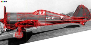
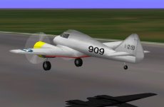
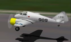
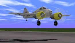
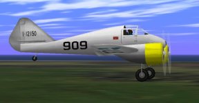
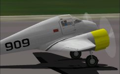
CFS1 Curtiss-Wright AT-9 "Jeep" Work In Progress.

Nacelle component

Hi Ivan,

Before doing the slide show I need a good screenshot of the model for it, and to get that, I have to correct a few things first.

I hadn´t lost the model I was working on after all! It was only the bleeds through the wing fillet that had come back because I was working on the AF99 model again.
Apparently on the SCASM-processed model, these bleeds don´t show, and neither do the gaps between the cabinframe struts and the aft cabin wall. Strange...

Anyway, the engine nacelles are now components, and I managed to get them in. At first I thought I could prevent SCASM from putting in new labels, which was naive of me. Of course there are new labels! I have already found the cabin-back and the dashboard. Now comes the floor...

With 144% parts count now, there may be enough parts left over to improve the monkey-heads I have as pilots!

Cheers,
Aleatorylamp
 
Last edited:
Hello Aleatorylamp,

I will poke around a bit at your AT-9 tonight. I have a technique which I demonstrated here a while ago which seems quite appropriate to this model and I believe it should clean things up a bit and maybe even save some resources.
If you send your latest AFX, I will use that for testing, otherwise, I will use the one I have now.

Regarding the mini drawing of the CW-21 (not B model), here is what I found so far that isn't quite right:The wing tip formation lights do not match the known configuration of those on the CW-21.The very prominent and heavy wing joint just outboard of the landing gear isn't even shown here.
The Fuselage panel lines do not match those that are visible in photographs and shown in other drawings.
As you mentioned, the top of the canopy is flat while it should be round.
The pitot tube is on the left wing completely inboard of the aileron. These ailerons look too far inboard.
The outer edge of the aileron should be even with the wing tip. This one stands too far away.
This is a CW-21 rather than a CW-21B and its cowl and fuselage shape are not quite the same.

- Ivan.
 
Not quite ready yet!

Hi Ivan,
On my new AFX, the new nacelle-component vertices don´t match the vertices on the old upper and lower nacelle wing-bulges yet, because I was still looking for the slanted 2D seatbacks on the SCASM listing, just to make that work. However, as you are working on the model, I will send the AFX anyway. Thanks many more millions!

Update: I´ve just found all the parts in the SCASM listing and compilation status says OK! However, file size is too large to update, so I´ll increase the heads parts-count and see what happens!

Cheers,

Aleatorylamp
 
Last edited:
Labels changed yet again

Hi Ivan,
After giving increasing the head bulkhead to 10 points instead of octagon, and addin one for a brow, several lables in SCASM changed yet again, and this time, after the label corrections, I´m getting a compilation error relative to the to the EndA command.
So, I´m unpacking the AFX I sent to you early this morning to get the same start-off point again.
I´ll try for the moment just to add an Octagon bulkhead to the heads - let´s see if it won´t change everything again.
Cheers,
Aleatorylamp
 
Hello Aleatorylamp,

Actually what you sent to me this morning was the AFA file which is just the assembly sequence.
I can't really do anything with that.

As for the SCASM error, there isn't enough information to diagnose from here.
There isn't any real reason to re-SCASM things until you are pretty sure about your MDL anyway.
It is just a lot of wasted effort if you do.
If you change the cross sections of a Structure, it is almost certain that things will get moved around.
I sent you the Pilot's Head I was playing with last night and it also uses the non-flat octagon cross section.
I actually tried to use a flat hexagon for the front bulkhead, and it does look nicer, but also increases the Parts count from 30 to 32.
My version of the Head Structure only costs 26 Parts at this point, but probably needs some tuning.

One thing I forgot to mention is that the Landing Lights you have on the underside of the wing are not really flush with the wing surface and appear to move with a changing viewpoint. Why not do them as a texture? It makes no difference unless you plan on animating them.

On the CW-21B Project, the Wire Frame over Photograph overlay is showing that I have LOTS of little pieces to move around. It is almost as bad as the rework I did on the P-40E. The biggest difference here is that it is much less certain where the pieces should actually be.

- Ivan.
 

Attachments

  • CW21B-Compare.jpg
    CW21B-Compare.jpg
    72.7 KB · Views: 0
Hello Ivan,
Thanks for your answer - I needed that information! Sometimes I do a SCASM process beforehand to check that things are working properly and also, for extra practise so I can remember things without having to look them up from the notes all the time.
Parts count is quite low at this stage, around 144%, and the head can support more parts if needed.
I´ll push the landing lights upward a bit, because I do want them in to light up and have landing beams.
Thanks for the newly sent files - I´ll study them and report back probably tomorrow, as now it´s a bit before midnight here.
As regards the new CW21B - not a piece of cake by any means, with so many adjustments to make. This may require a more laid back approach, doing only a little every day so it doesn´t get tedious, but it´s only an idea!
Update:
I put in the new pilot´s head and it looks much better already. The modified side shape looks better! I´m also thinking of making some shapes on the Jeep rounder too, which will be lengthy, so I can apply this to myself too!!

Your superimposed wireframe technique is great! Depending on how far away the photo was taken, probably quite near and without a tele-objective, the prespective would perhaps make the wing-tip larger, so that is one area maybe not to work on - but it´s your project, just an idea on my part.
Cheers,
Aleatorylamp.
 
Last edited:
Further progress

Hi Ivan, Hi all - having a nice summer?

With the Fledgeling, things are coming along slowly but nicely for the moment:

I´ve tidied up the vertices on the new nacelle component. I wanted it in, as I hated thr hairline crack cuased by the nacelle structures! Then, I also pushed in the fairing/inner wing division and slipped in vertical fuselage/wing templates, which seem to work, although they aren´t slanted like the ones in the AF99 "instruction" manual. I still have to clean up some parts at the front of the wing-fairing and match all the flap sections again, but that´s no big deal.

Well, I wanted two more components for the nose to get rid of the point just ahead of the dashboard, because no structure template exists with an upper flat surface except the flat octogon, and there´s no way I´m going to use that.

So, to free two components, my experiments with using a structure for the gear-up half-wheels were terrible: The inner lower wing-bulge started bleeding through the fuselage, and the wheel-wells display was upset, even though I had taken away the seatback structures to free some parts. And I was only at 146.7%...

Pity about the seat-backs, I rather fancied them, but they don´t look real anyway. Being a sheet-metal cup thing lined with fabric and probably slanting back is difficult to display anyway! Putting in 2D instead of 3D parts there causes cabin-floor bleeds through the cabin walls, as well as crew-abductions!

Joining the upper and lower wing-bulges didn´t work either (of course) as the bottom one bled throught the wing, and I didn´t even dare to put both wing-bulges into the inner-wing component - I can´t manage display-order of parts inside components yet, so I had to give all that a miss to!

But eventually I did manage something very easily:
I exchanged the prop-blade components for individual prop-blades, and successfully sequence-glued them onto the engine-front together with prop-blurs and prop-axels! Ha!

Now this has freed the 2 components I need for the nose so I can re-build the nose as one or two component to fix the forward cabin display problem, and maybe even the texturing issue.

I´ll keep you posted!
Cheers,
Aleatorylamp
 
Hello Aleatorylamp,

Exchanging the 3D seat backs for 2D should not require any differences in glue.

The substitution of Structures for Components for the Retracted Wheels should not make any difference other than freeing two Components and spending a few more Parts.

I wish I could put something together to demonstrate but my tools are very limited right now because I am on vacation down in Virginia Beach.

- Ivan.
 
No hurry!

Hi Ivan,

No hurry and no worry!

It may simply be that the 2D seats aren´t visible in the unSCASMed model. I can put them back easily because I printed out the glue-sequence - ha ha! I hadn´t tried processing the model with SCASM again because of the difficulty of finding the 2D seatbacks in the listing.

With the tucked-wheel structures (22 parts each), it rather looks like a matter of high parts count. At 149.9% there´s a problem which didn´t happen before at 143.9% (components with 8 parts each), and there are still a few vertices to clean up.

Anyway, the coming nose components which are intended to correct the front wind-screen-bottom area, will also save on parts. However, the tucked-wheel structures won´t really be necessary because I already got the components out of the props, and I can use the 2x14 parts difference elsewhere - for seatback structures again... ha ha, only joking!

Enjoy the beach!
Cheers,
Aleatorylamp
 
Canopy frame shape nicer

Hello All, Hello Ivan!
I hope you are all enjoying the summer, which is one of the main things!
As far as modelling is concerned, the extra parts retrieved from some improvements elsewhere on the Jeep, have gone towards a rounder more nicely shaped canopy, more like the real thing. Sometimes it was difficult to shape parts without bending them, but I got quite near. There were even some parts left for small issues like an extra little structure to cover some concave corners on the fin-base, and now we are at 148.6% parts count.
Not quite finished, but getting better!
Cheers,
Aleatorylamp
 

Attachments

  • newcabin1.jpg
    newcabin1.jpg
    36.4 KB · Views: 0
  • newcabin3.jpg
    newcabin3.jpg
    48.6 KB · Views: 0
909

Hello Aleatorylamp,

I thought you were going to change the paint scheme to something other than"909"?

Regarding 2D Seat Backs, there should be no great difference in visibility between 2D and 3D.
Do you happen to know what the real seats looked like?

Is there a "walk around" for the AT-9 at the Air Force Museum?

- Ivan.
 
Paint scheme

Hi Ivan,
Good question!
My intention of changing the paint scheme occurred when on a close-up museum-photo of the "909" Jeep I was shocked to see a sign with a text about a target drone, as i had immediately related the sign to the Jeep.
Well, looking for photos of the U-124 Jeep paint scheme on Paul Matt´s drawings, I came across another museum photo of the 909 taken from further away, and infront of the aforementioned sign, there was a 2-cylinder, red-winged target drone, with a wingspan of I suppose about 6 ft! Obviously the sign was meant for the smaller plane, so my dismay quickly dissipated. I like the yellow engines, and I´m also trying to include the little red sign behind the side windows on the textures.

Nevetheless, the U-124 paint scheme is also attractive, with its anti-glare matt-black inner nacelles, so I will provide both liveries. Paul Matt is very precise on the description of the lettering and such, so this can be interesting. His drawings of the plane are really good, I must say!

I´m still searching for pictures of the Jeep´s seats. I think I can still fit in some 2D ones, but the cabin shape improvement was more important!

Cheers,
Aleatorylamp
 
fuselage width adjustments

Hi Ivan,
With Paul Matt´s drawings I could now adjust the fuselage dimensions more exactly - the width was almost 11 inches too wide on each side, which made it a little fat-looking. That´s better now too.
Once I´m done I´ll have to ask you about SCASM again, to flip the canopy frame and include it for the inside view. The frame now has more parts at the back so that the windows don´t reach the back wall, and the spars are better placed. Anyway, there´s time yet, so enjoy the beach!
Cheers,
Aleatorylamp
 
Hello Aleatorylamp,

Actually we drove home from the beach yesterday. It was a good vacation though the injuries were not so good.
My daughter is still on crutches which wasn't such a big deal on a single level apartment, but at home life is a bit more difficult.
I am glad she is otherwise healthy and incredibly strong for her size.
Anna Honey still has a weak knee, but can navigate the house and even stairs without a cane.

Paul Matt's drawings are generally pretty good when they are available, but they are not always correct. Unfortunately for me, his Corsair drawings are not as good and his P-36 drawings have their inaccuracies as well. The Corsair has some shape problems which bother me so I need to use other references. The issues with the P-36 are along the lines of the corrections I was making and still need to make on the P-40E. They are not visible from a Simulator view but I know the issues are there.

With the AT-9, you really have no other place to go because there isn't another set of better drawings. At least I don't know about any.

Flipping the Canopy Frame is a very easy process. It only takes a few seconds after the code is extracted from the SCX file. The program I wrote still has issues occasionally but generally the issues are not hard to find.

Need to go help with Lunch.
- Ivan.
 
AF99 structure: triangle + dome bulkhead combination glitch

Hello Ivan

I hope your girls get over their ailments quickly! At least nothing broke.

As regards the "new" AT-9 drawings, comparing them to photos, they do look more correct, which is greatly satisfying. The blurry copy I had of one of them was useless, as were the others I could get my hands on!

Incidentally, I tried improving the instrument console structure (top half only), with a triangular bulkhead on the front to fit the top of the nose component more snuggly. This part isn´t really flat, but a little curved, so I had to use a slight point here, but not as pronounced as on the previous structure. I combined it with the rear dome-bulkhead, but unfortunately the lower-left side-triangle´s forward point does not join the left-front vertice, but instead goes into the centre, creating a gap on the console-side and a bleed into the middle. Strangely, it doesn´t happen on the right, and the templates are all correct... some glitch.

Anyway, I worked around that by adjusting the template-height in the front and using a dome-shape there too, and the difference presents no visible gaps.

Well, now I´m going to give all the parts more logical names, in order to re-arrange them, so as to avoid further confusion.

OK, then. Cheers for the moment,
Aleatorylamp
 
Fledgeling´s Progress

Hi Ivan, Hi all,
After a rather energy-demanding final end-spurt last week, the intensive German course for waiters is over, and with a few days´ rest the brain is probably AF99-able again.

I again found the museum walk-around that you mentioned, and noticed that the formation lights in the nose-tip and underneath shown on Paul Matt´s drawings are not present on the 909, so the drawing most probably shows an AT-9A.

Both colour schemes are appealing, and there are enough textures to duplicate the engine nacelle textures to include the upper-inner anti-glare matt-black. I can also save on a component and a texture as the nose-tip has no number on it.

The CoG shift to the aft-cabin bulkhead was necessary to fix cabin bleed-issues. As the windows are in reality smaller than what I had at the time, I put in some narrow side-panels in front of the bulkhead. This looked good on the side being viewed from, but was annoyingly invisible on the opposite side, because the inside cabin frame is not shown viewed from outside. So, being a waste of parts, I eliminated them and moved the bulkhead forward by 0.3 ft. Hopefully this will not cause any problems, now that the CoG is a little behind the bulkhead. The little issue of the pilot´s head bleeding through the aft cabin side-spar at an extreme angle has however improved! ...Maybe I´ll move the pilot in a little.

The vertice clean-up and the panel-beating to fix concave parts is proving successfull, even if it is taking a little longer than expected.

Also, there are now two fuselage textures instead of one, which will hopefully improve detail quality on signs and numbers.

Then, I have re-named all the cabin, wing-fillet and engine-nacelle component parts, hopefully in a way that will not be more confusing than before. This was easy by having two versions of the model open with AF99 simultaneously.

As regards the tweaks on the .air file that you had done, these have made all the difference, and the flying sensation feels very close to what it must have been in reality!

I have attached the .air file in case anyone would like to use it while I finish the visual model.
As soon as I have some presentable results I´ll attach a new version of the AFX.

Incidentally, I found a picture of the seats on a plastic model cutaway - looks like normal rectangular shaped seats without head-rests, with 5-inch foam upholstery covered in brown immitation-leather, if they had that in those days.

Another thing is that the comment I found about there being 4 seats in the Jeep must be erroneous, as all specs mention only 2.

Cheers,
Aleatorylamp
 
Hello Aleatorylamp,

My belief is that it was actually the glue assembly sequence that cured the cabin bleeds.
The location of the cabin's aft bulkhead wasn't really the issue in my opinion.
I moved the CoG to that location because it really should have been around there to begin with. Note the lift points on the Paul Matt drawing.

Please note that the cockpit aft wall usually does not coincide with the CoG. They almost never do on the single seaters with the cockpit well aft of the CoG and it doesn't on my MitchellC either and the cockpit is well forward of the CoG.

Glad you like the AIR file. I actually have very little idea how that aeroplane flew. I was just basing my tweaks on hopefully reasonable guesses and trying to discount the greater exaggerations of the actual pilots.
It is actually a fairly lightly tweaked P-51D file that I use as a known starting point. Most of the changes are just to reflect the physical characteristics.

- Ivan.
 
Slowly but surely

Hello Ivan,
Thanks for your indications on the CoG. I do believe there was one small bleed-issue at the aft cabin-wall against which the CoG shift helped, but of course the glue-sequence was crucial!

It has taken a while to achieve improvements worth mentioning, but at last, shapes fit better. One improvement led to another, and it took longer, but was worthwhile! Parts count is at 149%. Textures are those of AT-9 No. 909, but still need panelling drawn on, and there will be new AFX for AT-9A No. U-124 (Paul Matt drawings colour scheme), as the model itself has one or two slight differences.

Cabin: Spars, windows and general roundness is more life-like. The new pilot shapes look great in there, and the console is corrected. There were even parts left over for seat-backs, so I could still use the special glue-sequence! I made a separate textured canopy-frame AFX for virtual-cockpit SCASMing.

Engine nacelles: I finally found the way to slant the rear part so it´s flush with the swept leading edge (see blueprints). This was impossible with the previous structures, and it took a while for the penny to drop! Bleeds are much better, although not gone completely, as upper and lower wing-bulges hook over leading edges. Then, the under-wing surface is finally flat, eliminating concavities. I have also used nose-wing templates, aligning them with nacelle-root and leading edge. I wonder if this is correct, because AF99-Help has them intersecting the nacelles.

Wing-fillets: I eventually found what was wrong, narrowed and textured them up/down like you said, and it made all the difference. The belly is flattened out, so bleeds disappeared from here too. I used wing-fuselage templates here, although I made them vertical, not slanted like in the AF99 help files. I wonder if this is correct.

Panel: I managed to make a new panel, which is not my speciality at all, but it´s better than the Extra 300 one - only for default gauges though, to keep things simple. It is based on a photo of the original, and the general instrument layout seems to fit. I did also use an extra window to fit in some rivetted canopy spars, which adds to the atmosphere. No big deal though.

I´m still fixing some minor things, but I could quite soon send you the AFX for SCASM processing, if that could be convenient for you. Meanwhile, here are some new screenshots and two blueprints. It´s cleaner now by far!

Cheers,
Aleatorylamp
 

Attachments

  • Screenshot-1.jpg
    Screenshot-1.jpg
    33.2 KB · Views: 0
  • Screenshot-2.jpg
    Screenshot-2.jpg
    41.1 KB · Views: 0
Last edited:
Two more!

Hi again,
Two more things are also better now:

- Finer wing-tips, involving triangulating a leading-edge rectangle to bend it into a better shape.
- The hump near the aft wing-root is more rounded. A badly bent part needed triangulating too.
...and, I still have 0.5% parts left for any other possible issues. Let´s see!...

I´ll have a try at the panelling lines now. Good textures are difficult - this is when I appreciate the meticulous job that Udo Entenmann was doing on my models all these years. Too bad that for the time being he can´t do any FS stuff. He was doing some great anti-aliasing, de-pixelization and metallics, but I am usually limited to cutting, re-shaping and pasting parts of his textures. I´ll see how the lines go...

Cheers,
Aleatorylamp
 

Attachments

  • Screenshot-8.jpg
    Screenshot-8.jpg
    41.3 KB · Views: 0
  • Screenshot-9.jpg
    Screenshot-9.jpg
    39.5 KB · Views: 0
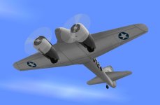
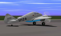
At-9a u-124

Hello all!
Here are some pics of the later AT-9A Fledgeling, in a more sobre but not necessarily unappealing colour scheme.
I wonder what colour the inside of the flaps really was? I only found one picture of a derelict AT-9 parked in the garden of some flying school with bright red inside, but that could maybe only have been that one unit.
I´ve found no other pictures, except for those of different aircraft, where this part can be olive-green, khakhi beige, polished aluminium, blue like on this one, or orange or even dark brown... so for likes, there are colours to choose from!

I wonder...
Cheers,
Aleatorylamp
 

Attachments

  • u-124-1.jpg
    u-124-1.jpg
    30.6 KB · Views: 0
  • u-124-3.jpg
    u-124-3.jpg
    38.9 KB · Views: 0
Back
Top