Conspicuous by Their Absence

Aircraft Trim

Hello Aleatorylamp,

Please go back to Post 1028. There is a bit of very useful information there.

One of my pilot's comments was about the consistent nose down trim.
Your post suggests it Should be a slight nose UP trim if the altimeter becomes steady with reduced power:

Steps to establish Cruise setting
1. Climb to operational altitude.
2. Reduce power until aircraft is no longer climbing.
3. Adjust Trim.

Note that these steps would make no sense if the aircraft were nose heavy or became more nose heavy as speed increased.

Regarding Maneuverability:
I will have to agree with my test pilot here.
The controls will need some adjustment to make this Big Duck qualify as maneuverable.

- Ivan.
 
Testing continued

Hi Ivan,
OK, thanks, I understand. I think I´ve improved the nose-down thing with the Pitch at AoA=0 parameter.

The purchase on the controls is also better now, by duplicating the moments for elevator and rudder, and triplicating the aileron one. I think it is more manoueverable now, without being too much.

Then the matter of the "C" for Chase View Window - that works only until Padlock Mode is activated. This is the bug you are referring to I believe, which you say can be cured with SCASM, which I don´t know how to use.
So, what would be better? Eliminating the virtual cockpit parts and placing that view (pilot´s position in the .air file) further aft and use that as Chase View, (and also using the 7 parts elsewhere in the plane, like two mechanics´ silhouettes in the engine nacelles), or perhaps kindly requesting someone to help out with SCASM there? More bother, I´m afraid...

Cheers,
Aleatorylamp
 
Last edited:
Chase View + Padlock=glitched view.

Hi Ivan,
My idea didn´t work - which I´d more or less expected... and you already know, I´m sure. Eliminating the internal view designated virtual cockpit parts didn´t help - they disappear anyway with the Padlock on Chase View. It´s other things that block forward vision - like the top of the Nose structure, and with rear view, it´s the inner parts of the rear fuselage. Virtual cockpit eye-point has nothing to do with it either, as I found out, and as you know already...
So, you said SCASM cures that. If it´s not too difficult, I suppose I could learn...
Cheers,
Aleatorylamp
 
SCASM Stuff

Hello Aleatorylamp,

I don't have a solution for the cockpit interior view. I know how to modify them, but I have basically been following a recipe I got from Hubbabubba a few years ago. It is a heavily modified recipe, but that is where it started.
For SCASM stuff, he is certainly a better source for advice.

As for the issue of maneuverability, there are a few ways to handle it.
You obviously can't make the control column require more force to move because it is only a little plastic thing wired to your computer.
Sometimes reducing the control response will give the proper illusion.
Sometimes modulating the control effect works.
(The control effect is very good and nearly linear to start. It hits a peak or its effect increases more slowly with increasing deflection.)

- Ivan.
 
Virtual cockpit view

Hi Ivan,
Normally, with hollowed out, windowed cabins there is no need for making extra internal-view-tagged parts for a virtual cabin, as the cabin parts themselves provide a decent internal view, but with this plane, the cabin is a solid block, and only 7 Internal View tagged parts are free for a virtual cockpit, and this doesn´t work with Padlock on...
To improve manoueverability, it is going very well at the moment by increasing the control moments, so that will be another problem out of the way! I´m also writing checklists, which are always nice to have.
Anyway, slowly it´s coming along.
I´ll keep you posted!
Thanks and Cheers,
Aleatorylamp
 
Reducing AF99 degree of complication

Hi again!

With the Giant failing to compile after 142.4 % degree of complication, I have just discovered that by un-texturing the shaded cabin-side and roof windows (top and side textures), it
has gone down and although it won´t allow the main wheel-hubs to have the front-wheel textures, it does allow two mechanics´ head silhouhettes to be put into the engine nacelles, using side applications of the front and rear gunners´ faces. The degree of complication is at 142.9% now, with 1143 parts

Edited Update: I´d thought for a moment that the lower AF99
degree of complication would allow doubling the front and dorsal MG´s, as some units had those, but there is no way I can free the resources. The guns appear to have been captured twin Lewis guns, so it doesn´t matter anyway.

So, I wonder which is better: The perhaps the strangely shaded, textured windows, or the simple 2D textured mechanic´s heads peering out of the engine nacelles - I can´t decide! What would a Simmer prefer?

Cheers,
Aleatorylamp
 

Attachments

  • windows textured.jpg
    windows textured.jpg
    50.1 KB · Views: 0
Last edited:
Sorry guys!

Ivan just send me an e-mail about the "Giant" that I could not have possibly missed. Well, guess what; I've missed it!:banghead:

The problem is that I'm using an RSS feed to keep in touch with latests threads, and "Conspicuous by Their Absence" is not fresh, to say the least.

Aleatorylamp, I will read your PM and respond to it, but, in the meantime, you should read my "series" of HTML tutorials at NoDice site; to be found HERE. This will give you a good basis for further conversation.

Thanks for the heads-up, Ivan. Otherwise, the obvious would have passed just under my nose!:engel016:
 
Homework

Hi all!
Not to worry - OK, thanks a lot.
I got a lot of stuff down from the site to study and I´ll do my homework!
Cheers,
Aleatorylamp
 
Hello Hubbabubba,

I was thinking that a quick lesson in how to set up a V Cockpit using SCASM like what you sent to me back in 2006 would do Aleatorylamp quite a lot of good.

- Ivan.
 
Homework...

Hi again,
No hurry with SCASM, my homework is very abstract, and I have to do the most basic thing as yet, which is to see how I can start the SCASM program first (the one that comes with Airport 26).

Then, I´ve also been looking into the DP tutorials as well, which are more understandable. As this plane was the equivalent in those days of a flying fortress, and all crew positions were armour plated, it may be worth while my thinking of the life points for the different sections of the aircraft.
Also, of course, flying Quick Combat against 2 Spitfires and 3 Mosquitoes is a bit unfair. A Sopwith Camel and a Vickers Gun-bus and perhaps a Voisin L5 would be better, but the question is how will the rear gunners hit them? Does CFS1 shoot really sideways and backwards as defined in the DP files? The plane is not really all that manouerverable so as to hit them all only shooting frontwards.

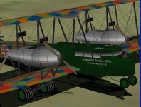
Anyway, thanks to Ivan´s SCASMing the virtual cockpit, the first Giant (Zeppelin-Staaken R.VI, built by Schütte-Lanz with twin tailfins and Mercedes engines) model is finished! Fantastic! Once the firing power and life points are decided, I suppose it will be ready for uploading.

As Ivan predicted, the SCASMed V-cockpit has left me with free parts to allow a central tail-fin and rudder for a three-finned Staaken-built version (with Maybach engines and darker blue night-bomber textures), and the model itself is done too. I´ll have to learn to SCASM it for the V-Cockpit. No hurry though, I have still to make the new textures and engines, 245 Hp rated at 8200 ft and 1400 RPM.

Cheers for now!
Aleatorylamp
 
Hello Hubbabubba,

I was thinking that a quick lesson in how to set up a V Cockpit using SCASM like what you sent to me back in 2006 would do Aleatorylamp quite a lot of good.

- Ivan.

I would have had to know the question before answering it. That's why I said that I would read the thread, the e-mails, and the PM to understand what you meant by "Virtual Cockpit". Was it the "no jittering" in virtual mode or the gauges in virtual mode, or something else, anyway...

Aleatorylamp; SCASM is an assembly language and need a GUI to work with, like Airport, EOD, etc... And the latest version available HERE is 2.96. To build (or rebuild) a/c, you will need Trevor de Stigter MDLDisAs that you can find HERE and a good TXT editor, this is the GUI I was talking about, but oriented toward aircraft (hence the MDL) than scenery.

You have to realize that pretty much all of my tools, and my e-mails, were lost when my W90SE machine went cold. And my own memory is barely better than that of my old rig.

BTW- You Riesenflugzeug look great, and would certainly benefit TG2 (Tail Gunner 2) for self-defense.
 
Scasm

Hi Hubbabubba!

The thing is to prevent the Virtual Cockpit from disappearing in Padlocked Chase View in Quick Combat mode.
Yes, I have found SCASM 2.96 and also the correct Disassembler (Ivan told me which to get), and put both it in C:\SCASM.
I know the WinXP console window is rather a pain, but I managed to start SCASM and Moldenhauer´s comments came up, but it didn´t find the Zep-R6m.mdl model file (that´s the new Riesenflugzeig with the triple tail. fin), although it was in the same directory as SCASM. I must have been typing in sth. wrong all the time.

I didn´t know about the GUI, but tried Emerald Editor (Ex Crimson so-and-so) but that crashed the computer, so I put it in C:\, but it was no good anyway.
I´ll see if I can find a better GUI.
Edited update: I just found the editor on Trevor de Stigter´s site and got his disassempler too - maybe it´s better than one I found.

I´m glad you like the Riesenflugzeug!
I´ll look for TG2 - I suppose it´s a plug-in for CFS1.
Better than firing in all directions almost at random!
Edited Update: I´m afraid I´m on Windows XP and TG2 is only for Windows 98. Pity!

Incidentally, I found the Scenery Editor inside CFS1 - Very neat!

Thanks for your support!
Cheers,
Aleatorylamp
 
Disassembler

Hi Hubbabubba, Hi Ivan,

Update: OK, the Disassembler I got from Trevor´s site works fine and I´ve just made an .scx file, so it appears that something has started to work. Let´s see what happens now!

Ivan: In the disassembled Text file of the Giant that you SCASMed, I´ve identified the Virtual Cabin text portion that you sent separately. Supposedly this text has to be inserted into the new Giant´s disassembled file (in a convenient place, possibly the same place?) and re-assembled again.
If I should need to colour the green parts of the V-Cockpit in blue, I could disassemble the new .mdl file of the V-Cockpit and insert that portion.

I´ll keep you posted.

Thanks a lot again!
Cheers,
Aleatorylamp
 
Jittering Cockpit

Hello Hubbabubba,

You're right. Your instructions were really to cure a "Jittery Cockpit". I expanded them to add in the Virtual Cockpit pieces and Canopy Frame, etc. Also added since then are adjusted animations though they are definitely not in my notes.

One funny thing is that the Jittery Cockpit doesn't appear in FS98 while the "Corrected" version wobbles all over the place.


Hello Aleatorylamp,

You can disassemble the models I sent you and see what kind of code I started with. The changes to your model were not terribly extensive, so they would not be hard to find.

- Ivan.
 
The importance of finely adjusting vertices

Hi Ivan, Hi Hubbabubba,

Once I get the set-up of SCASM and Disassembler running, which it doesn´t do yet, I´ll be able to start SCASMing. I may have to get the 12-year-old laptop I have here running on Windows 98 again for that.

Meanwhile, though, something perhaps equally important, if not more:
Ivan, I remember reading in one of your posts related to precision-building component parts (the P38 thread?), that even slight mal-adjustment of vertices (happens when working with low Zoom), increases the number of vertices in the component and causes excessive calculations which increase AF99 degree of complication.

The Giant is an upgrade on one of my earlier models (2003), when I still had trouble making wings. I never got round to cleaning up the vertices until I changed the wing-tips for the horn-balanced ailerons of the new Maybach-engined Giant a few days ago, so I took the opportunity to clean up both wings. This then coincided with your comment on the wheels, whose parts were also not perfectly aligned, so I cleaned those up too.

... and sure enough! Lo and behold! Instead of failing to compile at 142.8%, I was able to keep on adding parts, and now it´s still compiling at 148%! So then I got on to the first Giant as well, and cleaned that one too, and this allowed me to add the second dorsal machine gun (apart from the ventral one). The pair now faces outward at angles, so the structures are more part-consuming, but AF99 still happily compiles at 149.5%! ...I´m sure I´ll find something to put in the last 0.5%!

So, there´s much to be said in favour of cleaning up the construction!

Cheers,
Aleatorylamp
 
Last edited:
Mismatching Vertices

Hello Aleatorylamp,

I have no idea where I may have mentioned the idea of mismatched vertices or polygons.

Here is why I made the comment that mismatches in the faces of a Component cause greater resource usage:
Take the example of a simple regular closed / solid cube.
We are all familiar with what that looks like.
It has 8 Vertices and 6 Sides. If this were a AF99 Component, it would use 6 "Parts".
Now lets take the SAME cube but take one face and move it outward very very slightly, say 0.01 foot.
We still have the 8 Vertices of the original cube but those now only account for 5 of the Sides.
The Sixth Side that was moved outward needs 4 more Vertices..... So....
The new misaligned cube needs 12 Vertices and 6 Sides.
AF99 still thinks the Component has 6 Parts.
The problem is that the actual code being generated now has to first define 12 Vertices instead of 8 even though it is still only drawing 6 Polygons.

This makes sense to do when you REALLY want a slight separation line, but is a waste of resources and unsightly if it is just a plain mistake. If the misaligned face were moved INward rather than outward, it would hardly be visible but would still would use more resources.

Hope that makes sense.
- Ivan.
 
Second Giant

Hi all!

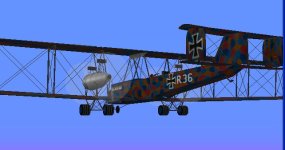
After cleaning up the vertices it´s looking nice, and there weren´t any problems to add the central fin/rudder and horn-balanced ailerons for the Albatros built Staaken R.6 with Maybach engines. The colour scheme is a darker splinter lozenge, slightly different from the Schütte-Lanz built version with Mercedes engines. The analysis of the black and white photos of the time offers different interpretations, so there´s room for speculation.

The engine tuning is going very well, and the difference to the Mercedes Engines is noticeable. These had a slightly greater cylinder capacity 233.83 cu. in) and slightly higher compression (4.94/1) and were rated at 245 Hp at 8200 ft at 1400 RPM - a bit slower than the Mercedes engines lower down, but 20 Hp more powerful higher up, with an almost 2000 ft higher ceiling, and the speed difference was only about 3 knots (3.5 mph). The Maybach engines were the preferred ones, but were scarcer and more expensive...

So now there´s two planes, almost ready for upload...

Cheers,
Aleatorylamp
 

Attachments

  • Staaken Maybach.jpg
    Staaken Maybach.jpg
    39.8 KB · Views: 0
Propeller Power Coefficients - Table 512

Hello All,

I am still learning about these Tables myself, so I am presenting what is hopefully a thought provoking topic as I experiment with it. I am sure that some folks already know more than what I am just touching on here.

My original goal with the propeller tables was to cure a bit of a problem with the Japanese A6M Type Zero Carrier Fighter.
My original flight model had fairly decent behaviour but as I found more information, my corrections to incorporate the new Propeller Pitch limits caused a bit of problem.
Without knowing any better, the original low pitch angle was 20 degrees.
A very nice gentleman sent a manual to me that showed that the pitch range was really 29 degrees to 49 degrees.

As soon as I adjusted the minimum pitch to 29 degrees, the propeller started lugging badly.
The engine would not achieve maximum RPM until 185 MPH.
I was pretty sure this was incorrect because in numerous flight test reports, a lugging propeller was never mentioned in any of them.
As a contrast, a lugging propeller IS mentioned in flight tests of the Ki-61 Hien.

After all these discussions on propeller power coefficients, I decided to make an attempt at adjusting the minimum airspeed for maximum RPM.

In a way, I was successful. The propeller now comes off 29 degrees minimum pitch at 110-120 mph now and although I can adjust it a bit more, I will do some testing here to see how the performance and handling has changed.

*****
 

Attachments

  • Record512_P-51D.jpg
    Record512_P-51D.jpg
    104.7 KB · Views: 0
  • Record512_Reisen32.jpg
    Record512_Reisen32.jpg
    105.9 KB · Views: 0
Advance Ratios AGAIN!

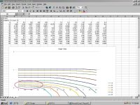
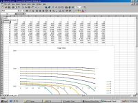
As can be seen in my prior post, the Red Circle shows the area of greatest concern in affecting the low pitch power required.

One other thing worthy of note is the Advance Ratio range that is typical of the stock aeroplanes and the shapes of the graphs.

Now HERE is where things get really interesting.
One of the things I have often wondered about is why although propeller overspeed was often mentioned in the manuals, it never occurred in the simulator even at dive speeds exceeding Mach 1 (!) (Yeah, we can't get to Mach 1, but curing that is a different topic.)

It becomes obvious as you look at the shape of the graphs.
The propeller begins to drive the engine when the advance ratio exceeds where the blades are edge on to the air flow.
For a pitch of 45 degrees, Advance Ratio (J) needs to be 2.36 or higher.
For a pitch of 50 degrees, Advance Ratio (J) needs to be 2.8 or higher, but the graph only goes to J = 2.4.
The Type Zero Mark II fighter has a maximum pitch of 49 degrees which means that the graph does not cover the area in which the airflow would be driving the propeller and possibly causing an overspeed.

When I got here, it occurred to me to do a little more poking around.
The sample Record 512 I typically start with is from the stock P-51D.
Relevant Details about this Aeroplane are:
11 feet 2 inch Propeller Diameter
0.479:1 Reduction Gear Ratio
3000 RPM Maximum RPM

Typical Maximum speed is 437 MPH for the pokey D model and 441 MPH for the B/C models. They became even faster with later models such as the H.

Now, taking all these numbers together, we get a speed of 439 MPH at J=2.4!
What this means is that the propeller tables don't even cover the speed range of this aeroplane in LEVEL flight, much less in a dive.

Now if we look a bit further, we can see that the first row of Table 512 is specifying the Advance Ratios.
Perhaps it is worthwhile to adjust the ranges here. Since each column is specified, it would imply that the spacing does not need to remain linear either.
I suspect that the reason for such a low range of advance ratios is because all of the stock aircraft are just hot-rodded Cessna 172s which don't really go very fast.....

Thoughts?

- Ivan.
 
Now to tie this in a bit....

Hello Aleatorylamp,

Your Giant project is the best test of what I was describing.
At the moment, you are stuck with 3 or 4 table entries to try to make a smooth curve for Table 512.
Perhaps it will be worth a test to reduce the range of Advance Ratios so that you have better control of the curve?

I know *I* will be trying something pretty similar shortly.

- Ivan.
 
Back
Top