Conspicuous by Their Absence

Flight model satisfaction

Hi Ivan,
It´s interesting that you know how to make useful programs - they come in handy! I can only program in QBASIC, and it´s a bit obsolete now... I haven´t learnt to use spread sheets either, so I´m limited to manual entries in AirEd, but it´s not too bad at all with CFS1!
To compare 2 .air files I always open 2 windows with AirEd open side by side, and go down both listings in order, and it works OK.

After the FS98 limitations that I have been used to until now, it is indeed satisfying to experience the increased control that CFS1 offers over aircraft performance! The main problems I ran into towards the end were my own fault, as I should have noticed that the .air file had something "broken" in it and renewed it long before. Anyway, I have just adjusted the second Giant´s better engines for 8200 ft rated altitude, and Hp is fine all round... I´m now adjusting RoC for different altitudes.

You mention fuel tanks: An interesting thing on the Giant was that it was fuel-trimmed. Prior to take-off, the angle of attack for the sustaining tailplane was set from outside, depending on the bombload to be carried, and then the plane was tanked up, always leaving the 2 foremost of the cylindrical inboard fuselage tanks empty. The Mercedes engined Giant had 8 tanks, and the Maybach one, 10. This way the plane was trimmed for take-off and climb. Then during flight, the fuel engineer could pump fuel into the two foremost tanks to change the CoG for level flight. He also kept the central tank under the top wing full to feed the engines.

A trimming-wheel was also available - it is visible on cockpit photos, but only used when the plane was empty and low on fuel, and there was nothing to pump into the forward tanks to lower the nose.
Anyway, in CFS there´s no fuel menu, so one can´t move the fuel around from one tank to another and the trimming wheel has to be used. For CFS1 I have only defined 2 fuel tanks, left and right, each with half the total fuel.

I´ll wait a bit for your notes on the V-Cockpit then, before I upload the Mercedes Giant.
Cheers,
Aleatorylamp
 
Broken?

Silly question, but if a side-by-side comparison of two AIR files isn't difficult, then why not figure out what was Broken in the AIR file and fix it rather than throw it away and start over? I find it to be tedious and very error prone to compare long files.
That is why I prefer to let machines do the text searches and matching for me.

By the way, Just a few minutes ago, I generated my first spreadsheet calculated Propeller Power Coefficient Table (512).
Though the curves are programmatically generated, the adjustments to curve parameters need to be entered by hand.
Actually only the positive values are tuned so easily. The negative side is also formula generated, but the formula is not easily tuned.

Now I just need to build a matching Propeller Efficiency Table (511) to test.

- Ivan.
 
Invisible Breakage

Hi Ivan,

Congratulations on your Propeller Making Machine! I bet that real propeller makers would love such a tool. Connect it to a computer and out comes a new propeller! Ferhaps in the future with a 3D printer! They have already printed a flyable 3-ft-wingspan plastic radio controlled model aeroplane!

.airfile breakages:
Maybe it´s a silly answer, but as far as I know, from what I have read (i.e. Tom Goodrick and Guder, and comments from my previous and retired FS98 .air file writer), the things that "break" are internal "mechanisms", not a parameter visible in the FD editor listing. Otherwise, after going systematically down through the newly loaded and conveniently re-named P51D airfile, and manually transferring the pertinent data from the "broken" .air file into the pristine new one, how else could it be that the unfixable flaw suddently disappears?

Cheers,
Aleatorylamp
 
Perpetual Motion

I bet the actual aircraft builders would much rather have a self energizing perpetual motion propeller instead.
I know *I* would prefer a real aeroplane that could fly around the planet with a single gallon of avgas.

If you send me both good and broken AIR files, I am sure a hex dump could find the difference. If I could find my old program, it could tell in a minute or two what record the error was in as well.

- Ivan.
 
FD breakages

Hi Ivan,

This is just to clarify that I must be wrong about broken .air files having undetectable flaws.
I had thrown away the "broken" one I couldn´t fix, so I can´t send you the file or test it, but I had one from a few hours prior to the "breakage".

I took it and put all the new parameters in there, and the .air file works fine! So, you must be right about the fact that a flaw CAN be found in an .air file, i.e. it isn´t an "invisible" internal thing that may break. It must have been something I´d done to it, obviously.

Perhaps Tom Goodrick and Guder´s comments about having to use a fresh .air file to start anew when problems become unfixable, referred to an accummulation of erroneous entries that were too difficult to put right, and it was easier to start afresh.

Anyway, it´s not a problem. What is a problem is that SCASM run from MDLDisAs V3.05 refuses to compile a new .md file due to errors, and I can´t get hold of the older V2.01 which as Hubbabubba says, seems to report fewer errors. I was reading the thread on the SCASM tutorial in Hubbabubba´s corner, but I can´t test anything as my version won´t work properly.

Anyway, if the virtual cockpit can´t be fixed, I don´t really mind, it´s not so serious, and I don´t want to cause so much bother. If course, if there´s light at the end of the tunnel, then I´ll try and make it work.

Cheers,
Aleatorylamp
 
Hello Aleatorylamp,

Please do check your email. I found something very old that might be useful to you.

Regarding Tom Goodrick and Rabbijah Guder: I don't believe I have seen anything recent from either of them. To me this means that their work and observations about AIR files was done at a time when there was much less knowledge available.
A lot of their conclusions although logical for the evidence available at the time is no longer valid as we find out more about the structure and contents of AIR files.

Another problem is that the AirEd.ini and FDECtrl.txt files which listed the "known" fields in the AIR file had much less content than they do now. That means that quite a lot of the AIR file was "invisible" to them.
That is why I suggested doing a hex dump of the actual AIR file to see where the differences are. A hex dump should show EVERYTHING whether or not the record is known.
I am quite glad that they did the poking around and reasoning and chose to document it because I started by reading their reports also. I also realised fairly quickly that a lot of their conclusions were a bit obsolete in light of then current knowledge and (recently) some releases of information by Microsoft.

There is also the possibility that the AIR file editors they were using had bugs that would sometimes corrupt the file in a manner that was hard to fix.

- Ivan.
 
Hi Ivan,
OK, good explanation! Thank you very much.
Some things evolve, and other things become obsolete and no longer apply.
That´s good - with modernized tools CFS1 won´t become obsolete for some time yet!
Another good thing is that some people know, and can spread the knowledge!
Cheers,
Aleatorylamp
 
Disassembler and SCASM works now

Hi Ivan,
Thanks a million for your help! My SCASMing setup finally seems to be working.
I´m now going through the instructions you and Hubbabubba sent me, in order to join the .scx listings of the separate v-cockpit models to the .scx listings two v-cockpitless Giant models, so as to re-compile them afterwards.
OK, then
Cheers,
Aleatorylamp
 
SCASM fixed Virtual Cockpit!!

Hi Ivan,
I can hardly believe it!! I inserted the V-Cockpit code into the Giant´s source file and the newly SCASMed virtual cockpit works perfectly!
I also had a look into Hubbabubba´s thread on AF99 colour codes in hexadecimal and with this info I was even able to find the individual cockpit parts in the source file and identify their vertices to eliminate some hairline cracks.
The next step now is to simply put the V-Cockpit code into the other Giant´s source code and simply change the dark green cockpit parts to dark blue, and presto!, the other Giant will have a perfectly working Virtual cockpit too!
I´m just tweaking a few things in the .air file and will be uploading the planes soon!

Who would have thought that an old dog could learn a new trick?
Thanks a million!!
Cheers,
Aleatorylamp
 
Second Giant V-cockpit also SCASMed

Hi again!
The second Zeppelin Staaken R.VI, with the Maybach engines, now also has its SCASM-fixed V-Cockpit.
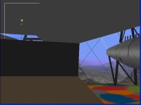
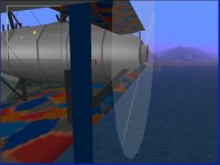
This one has a slightly darkened night-bomber splinter-lozenge livery in dark-blue-blue-orange-red-grey with a blue cabinroof and blue interior window frames, whereas the Mercedes-Engined Giant has a green forward-fuselage and window-frames, and an overall brighter conspicuous anti-friendly fire colour scheme in green-red-orange-blue-dark blue.
As soon as I´ve finished last minute adjustments on the .air file i´ll upload them.
Cheers,
Aleatorylamp
 

Attachments

  • V-cockpit1.jpg
    V-cockpit1.jpg
    32.5 KB · Views: 0
  • V-cockpit2.jpg
    V-cockpit2.jpg
    39 KB · Views: 0
Cool Looking Giant Aeroplane!

Glad it all worked out for you.
It does look cool from the screenshots.

I have also made some progress with the Propeller Tables.
Hopefully there will be something worth flight testing shortly.
The candidate for flight testing is a Ki-61-Id that has been waiting its turn in the paint booth for years.

- Ivan.
 
Volunteer for flight testing

Hi Ivan,
Tell me what you´re testing for and I´ll I volunteer for the task!
Cheers,
Aleatorylamp
 
Flight Testing a Propeller

Thanks for the offer Aleatorylamp.

I don't think this is a task that I can delegate though, especially not with the first try at Propeller Tables.
I suspect testing this time will be a bit different from my usual protocol.

My plan (very subject to change) is this for now:
Gather enough information for a data sheet on the Kawasaki Ki-61-Id.
I MIGHT already have this but can't tell right this moment because any data and references would be on the HDD for my dead laptop.
(It would also help if I could remember where the notebook is that contains all my old test record sheets.)

Run a full flight test on the Ki-61-Id (version 0.55) with the propeller as it currently stands.
Engine Power at various altitudes
Level Speed at various altitudes <-- This is the part that takes the longest
Climb Rates
Service Ceiling

Also note the Propeller Pitch, Thrust, etc under various conditions.

Tune the Propeller Tables via Spreadsheet.
Plug in the new Records 511, 512.
Re-Test.

There ARE a couple new developments though.

A replacement for my dead laptop was ordered last week and should arrive in a few days so I will have a place to load all the accumulated data from the old machine. Just need to figure out how to get license from the old MS Office and Anti-virus onto the new machine.

I also found my command line Spreadsheet to AIR File record conversion program. It actually was written back in September 2010 from the date of the source code file. Now I just need to go over the program and make sure it does what I am expecting.

Plenty of things to do.
- Ivan.
 
Extensive plan of action

Hi Ivan,
I feared as much... It is an extensive and detailed plan of action.

I know your plane is very different from the Giant, and requires different testing, but should you need a timed cruise-climbing test at a set elevator trim setting (or with minimal corrections along the way) from sea-level to ceiling, I could do it, noting down RoC, Mph-TAS, RPM and Hp, for every couple of thousand ft or whatever interval the higher climbing speed will allow. I could also do level flight testing for different altitudes - I know they take a bit of time as one has to wait for the plane to balance itself out, but it´s no big deal.

So: Just in case you need it! Not a "Zwangsbeglückung" like the Germans say, i.e. an "obligation to be made happy". They like to make up words that require a whole phrase en English!

I´m glad about your laptop! Often they can´t be repaired for a reasonable price.
Cheers,
Aleatorylamp
 
Creating Test Protocols

Hello Aleatorylamp,

Thanks for the offer. It IS appreciated, but probably won't do me much good at the moment.

First of all, the extent of testing varies quite a bit depending on how much information I really need.
For example, the Me 109E Trop that was done a little while back had only the amount of testing necessary to give it the handling I THOUGHT a 109E should have and the basic straight line performance, climb rate and ceiling.
This meant that I only did speed tests at 500 feet and around 15,000 feet (?). (I can't remember the exact altitude but it was wherever the engine power started to fall off.)

On this test, I am guessing I will be doing speed runs with notes on propeller pitch and thrust EVERY 2,500 feet.
There may be the need to record more numbers when things don't work as expected after the propeller is changed.
Keep in mind also that I will most likely make changes to the propeller tables as I find things that don't quite work.

The general flight model for the Ki-61-Id is also very much my interpretation from doing a fair amount of reading.
The Allies tested captured examples at 348 MPH. There was a great reluctance to test at high power settings because of the perceived unreliability of the engine. (The total flight testing was very short duration and was terminated by a main bearing failure.)

I believe that 380 MPH was closer to what the airframe really could achieve for the following reasons:
IIRC, the Japanese claimed 367 MPH but their testing was probably done at a much lower power setting which was their usual practice.
The Kawasaki engine was a "copy" of the Daimler Benz DB 601Aa but with local "improvements". It turned out that the improvements were mostly detrimental and the Japanese were not able to achieve the supercharger performance that the Germans had in the original.
Also, this engine model was quite poorly made in general. Most were not reliable or could not achieve the output that was claimed. This fragility might explain their low Manifold Pressure limits at altitude which are well below their Take-Off and sea level settings.

As we have already observed, my mechanics are much better trained than the typical Japanese Army mechanic. They have corrected the issues of unreliability that were so prevalent in these engines. The fuel we are using now is still only 92 octane but does not contain pine root oil or other extenders, so we are able to run these engines at the designed settings.

- Ivan.
 
Testing

Hi Ivan,
How insteresting - there seems to have been a lot of "shared" technology going round then.
I´d agree with you, that there is not much point in CFS for using a below-par quality engine whose main bearing goes after a short test, so FD parameters would obviously be set to simulate a good example of the engine, if not on par with manufacturer specifications, then at least (or perhaps better) on par with reports by pilot´s of the time who actually flew them, as you said.
I found that allied testing reports sometimes give confusing results, as has happened with British tests reports on the early German "overcompressed" engines. Often, the reported designation was not even correct, and as they didn´t really know how exactly they were to be operated, the testing conditions didn´t really fit the real engine performance. They did however seem to have been better at testing normal aero-engines, not of the "a" or "aü" type!
Did you get the Mercedes-engined Giant I sent for a short final test last Wednesday? There could be some problem with e-mail traffic again.
Cheers,
Aleatorylamp
 
Concept question: Engine+Propeller+airframe=performance

Hi Ivan,
I have a concept question for you, as I can´t solve the balancing out of the parameters for the Maybach engined Giant, where I´ve been trying to adjust all the different parameters that affect power and speed.
Either RPM is OK and Hp 25 hp too low, or RPM and climbing are too high and Hp correct. I was also re-adjusting the Propeller Efficiency and Thrust tables.

On second thoughts now, I wonder if perhaps the propeller tables needn´t be touched, as these fit aircraft speeds rather than engine RPM or altitude. Perhaps, really only the Torque graph needs adjusting (with its dip 100 RPM before before full PRM), and the Friction Graph, after setting the compression and boost-gain parameters, of course.

The aircraft is basically the same as the Mercedes engined one, except for 500 lb more dead weight (the engines were heavier), and the engines very similar, but better.

Performancewise, the Maybach engined aircraft:
a) higher compression: 233.83:1 instead of 200.6:1
b) had a 1700 ft higher ceiling: 14,100 ft,
c) got its full 245 Hp at 8200 ft as opposed to the other´s which was 267 Hp at 4300 ft., (boost gain was 1.4 instead of 1.22), meaning that when the Mercedes engine got to the Maybach´s rated height, it had already lost a lot of its 267 Hp, and the Maybach one was at peak performance.
d) was 3.5 mph faster at full speed level flight, with 84 mph TAS instead of 80.5
e) average RoC was 328 fpm, 33 fpm higher than the other´s 295 fpm
f) Full RPM was 1400 instead of the other´s 1450 RPM

So the question is essentially:
Can the 2 Propeller Tables in theory be left alone?

Thanks in advance for your answer. No hurry!
Cheers,
Aleatorylamp
 
Adjustments

Have you actually tuned the engine RPM setting in the AIR file?
You should not be exceeding the RPM limit under normal flight conditions.

As for what exactly is happening when RPM is too low but HP is correct or HP and Climb are too high if RPM is correct, I would actually need to test it myself to see what is happening.
I have already told you the way I would do the tuning, so there is no other information I can give that is new.

Please check your post in the area regarding Compression Ratio.... The numbers that are listed do not make sense.

My guess is that with the difference in HP and RPM between the two engines, you will need to do some tuning in the propeller tables.

My apologies for not giving much detail, but I can't visualise what is actually happening with just the numbers provided.

- Ivan.
 
OOps!

Hi Ivan,
I´m afraid that my migraines sometimes take their toll.
I do apologize - it doesn´t make sense indeed! I meant to say:
a) i) higher cylinder capacity: 233.83 instead of 200.6 cu. in.
ii) higher compression rate: 6.08:1 as opposed to 4.94:1.
The first thing I´m trying for is to get the max. RPM right.
Thanks for your answer on the propeller blades tables! That was really all I wanted for the moment, otherwise I would be too much of a bother. I shall proceed accordingly!
The necessary friction graph setting is becoming enourmous: I had it at 100 and now it´s almost 250! It seems abnormal though, so I´ll see what can be done with the propeller tables.
Thanks and cheers,
Aleatorylamp
 
Propeller Tables

My son happens to be working on Algebraic Functions in school and I showed him a couple tools I had used to work on the Table 512 template. We didn't actually get into the exact result and I don't know if he would even recognise the results in my spreadsheet, but he at least has the basis now to get to the same place.
All of these computer tools and the Internet simply didn't exist when I was doing the same things in school.

Now I just have to get him to WANT to figure out what I am doing..... That is a much harder task because Los Santos and Liberty City are much more appealing to him in comparison to plotting curves on a spreadsheet.
"So what the heck does your spreadsheet have to do with playing Combat Flight Simulator???"

He would much rather pilot a Pod Racer through a maze than flying the Warhawk through the Eiffel Tower.
I still have not been able to get him to keep only one hand on the stick so that he can use the other for the throttle or other controls.

Sometimes I wonder also if my time would have been better spent playing Sudoku. At least then my wife would not wonder all the time why I am playing on the game computers.

- Ivan.
 
Back
Top