Conspicuous by Their Absence

Fewer Columns?

Hi Ivan,
With the current problem of the Giant not slowing down for landing but gliding on in idle ad-infinitum at 150 ft and 50 Kt, I´m game for trying whatever will help! I´ve increased Zero Lift drag, Induced Drag and comensated Prop Efficiency, and slowly it´s getting a little better, although RoC is a bit high now.
Do you mean reducing the number of columns and perhaps trying out the 30 degree pitch column?
Cheers,
Aleatorylamp
 
Hello Aleatorylamp,

Actually the total number of columns would remain the same, but the intervals might be closer.
As an example if the Advance Ratio were incremented by 0.1 between columns instead of 0.2, you would only go from
J=0.0
to
J=1.2

This seems to be quite sufficient for the Giant and similar machines: J=1.2 would mean a forward speed of around 275 MPH which the Giant and its brethren are not likely to reach, at least not in one piece.

I have just the opposite problem with WW2 Aircraft. The range of Advance Ratios needs to be increased, but the question is how much would be reasonable without losing the ability to fine tune the low end where it is more important. Also, in theory, a non-linear graph SHOULD work, but I am wondering how I would go about testing whether something is working or not.

At the moment, I am going back to basic Geometry and Trigonometry to figure out if I can generate a reasonable approximation of Table 512 using a spreadsheet.

One thing worth noting is the entry for 45 Degrees pitch at J=2.4. Simple Geometry states that the power coefficient should be Zero or slightly negative since the blade section would have zero angle of attack to the airstream at J=2.36.
Notice though that the P-51D graph does not do this. Then again, perhaps I do not understand this problem well enough because I have drastically simplified things.

- Ivan.
 
Partial Success

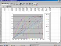
Last night I did a bit of tuning to Table 512 for my Kawasaki Ki-61-Id.

The results are a bit interesting to say the least and I will need to do some more changes before this graph is useable.
First, I was able to adjust the propeller so that it now reaches full 2500 RPM below 150 MPH.
It is only 145 MPH which isn't much but then again, I only changed the values by 3-5% just for testing.
Idle speed is a bit higher 465 RPM instead of 450 RPM. I have no doubt I can drop a bit more with no great issues.

Unfortunately I could not resist "fixing" the curves that were so strange looking so now the general propeller pitch is quite a bit more coarse in normal flight.

The worst result though was to change the value for 45 degrees pitch at J=2.4.
The propeller now DEFINITELY overspeeds in a dive.
The problem is that it doesn't slow down much after pulling out of the dive.
The extra thrust from the overspeeding propeller keeps the aeroplane going quite fast for a LONG time.

Time to step back and review the results from the quick experiment. I was pretty sure that tuning by eyeball wasn't going to work well, but now that I have a smooth curve, I can adjust it very easily in Excel without any great effort.

There is quite a bit more in the plans, but they not worth mentioning here because they are quite indefinite at this point.
It is amazing the kinds of silly things we can make happen with these graphs.

- Ivan.
 
New propeller for the Giant

Hi Ivan,
Whoever would have thought that J settings could be altered in the first column of the 512 and 511 propeller tables!
So, sticking to the 25% Pitch column for the Giant´s 14 ft wooden prop, as far as I understand from your investigation results, instead of having the J settings going up by 0.2, one can regulate them more precisely within a desired operating range, having them go up by only 0.1 or even 0.5.
I inserted an extra line for J=0.35 becuase it seems to coincide with the top level speed at rated 4300 ft altitude: 80.5 mph (70 kt). Then, with the Vne being 93 mph, the J=0.04 (92 mph) value could perhaps be set at 0.0405.

Now the J setting distribution for the Giant´s speed range looks like this:
J=0.00... 0 mph
J=0.10... 23 mph
J=0.20... 46 mph
J=0.30... 69 mph
J=0.35... 80.5 mph
J=0.405.. 93 mph

Previously, both Zero Lift and Induced Drag were far too low, so I duplicated them and compensated the lower speeds by increasing the J=2.0 prop-efficiency setting from 0.45 to 0.75, obtaining better descent results and more or less maintaining preformance: Level flight stayed the same but RoC went up too much.
............Eff......Thrust
J=0.0.. 0.050.. 0.0135
J=0.2.. 0.750.. 0.0100
J=0.4.. 0.010.. 0.0086

Now, with the compensated prop efficiency for the increased Drag, I´m trying out the new propeller with more settings, efficiency and thrust values initially distributed as follows, and it generally seems to be working.
...... .......Eff.....Thrust
J=0.00.. 0.050... 0.0135
J=0.10.. 0.450... 0.0110
J=0.20.. 0.650... 0.0100
J=0.30.. 0.700... 0.0095
J=0.35.. 0.750... 0.0090
J=0.405. 0.010... 0.0086

This distribution will hopefully let me fine-tune things a bit more! Now I have to test it more meticulously. I´ll keep you posted.

OK, then,
Cheers,
Aleatorylamp
 
Hello Aleatorylamp,

I am certain that other folks have figured this out long before now, but to me this is new.
Hopefully no one minds my posts and probable missteps as I explore this area for the first time.
The numbers you are posting for your Giant imply that nothing significant is being changed in the flight model other than giving the ability to fine tune the Propeller parameters. Obviously you figured out that the varying interval works as well.

I did one more test yesterday that also results in the same conclusion.

- Ivan.
 
Some Quick Testing

The results from looking at Tables 511 and 512 didn't seem logical.
I was wondering if perhaps the numbers we interpret to be Advance Ratio were actually 1/2 Advance Ratio or something else that would mean that these Tables were specifying settings at a much higher speed than it appeared.

The next step was how to set up a test that would "prove" that the value we interpret as advance ratio really was that AND to confirm that I had not calculated Advance Ratio incorrectly. (It is a very simple formula but who knows?)

As a test, I took a copy of my Kawasaki Ki-61-Id (the original version without the latest propeller modifications) and used AirEd to change all of the propeller efficiencies above J=1.0 to be Zero. The column for J=1.2 was also reset to be J=1.05.
So.... This fancy new propeller produces normal thrust at or below J=1.0. Its thrust drops rapidly to nothing as it hits J=1.05.

Ki-61-Id Relevant Information:
Propeller Diameter 9.84 feet
Reduction Gear 0.646:1 <----Inverse in the AIR File.
Maximum RPM 2500

From this, Advance Ratio J=1.0 corresponds to 180.64 MPH and J=1.05 would be very close to 190 MPH.
The test showed pretty much normal behaviour until a maximum speed of 187 MPH was reached at which point the aeroplane would go no faster. Increasing the drag by lowering the landing gear reduced speed to 186 MPH.

I also found that my interpretation of zero thrust when the blades were at AoA = 0 to the relative air flow was incorrect.
I did my calculation based on 0.75 Radius because that is typically where the blade angle is determined. We know it can be no more than 100% of the Radius though, so the limit is certainly no more than 33% higher than my earlier calculation.... Unless we take into account about 1-3 degrees difference to the angle of zero lift because of a cambered blade.... I am making a lot of assumptions and guesses here, so perhaps someone knowledgeable should step in?

*****
 
Numbers versus Reality

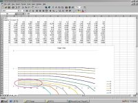
Here again are the Tables 511 and 512 for the stock P-51D Mustang.
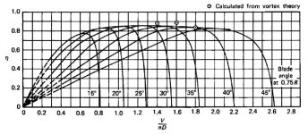
Also attached is a Propeller Efficiency Graph calculated using Vortex Theory.

For this exploration, I will use a Propeller Pitch Angle of 25 degrees because it is within the operating range of the P-51D.
Note that the Vortex Theory Graph shows that Efficiency drops to Zero at just below J=1.3.
This is happening because the relative air flow to the Propeller means that at any forward speed above J=1.3, the AoA of the blade is negative.

Next, note that Table 512 shows that the power absorbed by the propeller drops to zero at slightly above J=1.2.
So far, so good. Things here are more or less consistent.

Now HERE is the fun part: Note that in Table 511, the Propeller Efficiency at 25 degrees is still over 0.7 at J=1.2....
BUT, Above J=1.2 or J=1.3, the power being absorbed by the propeller is NEGATIVE. I interpret this to mean that the airflow is making the propeller spin faster which makes sense from a geometry standpoint.

So if I am interpreting things correctly, what we have here is an odd little perpetual motion machine. The airflow drives the propeller. The propeller gives thrust which increases the forward speed and advance ratio which drives the propeller even more. The only thing preventing the world from melting down at this point is that typically the maximum pitch is much higher than 25 degrees and the constant speed governor keeps raising the pitch. That would explain the serious overspeeding I was getting in the Ki-61 flight test.

Next step to check whether my interpretations are correct is to either setup a propeller with a very low maximum pitch or manually reduce the pitch if it is possible in CFS.
Does anyone know what happens if we specify a propeller as Adjustable Pitch rather than Constant Speed?

- Ivan.

Next
 

Attachments

  • Record511_P-51D.jpg
    Record511_P-51D.jpg
    94.3 KB · Views: 0
  • Efficiency_VortexTheory.jpg
    Efficiency_VortexTheory.jpg
    50.1 KB · Views: 0
  • Record512_P-51D.jpg
    Record512_P-51D.jpg
    104.7 KB · Views: 0
fine-tuning going wel!l

Hi Ivan,
Very interesting indeed, your findings!
If I understand correctly then, on a constant velocity propeller, in a dive, the governor reaches the maximum high-speed setting after which prop-overspeed occurs. On an adjustable pitch propeller, I wonder if by manually changing the angle to a less feathered position, one could actually use the engine as a brake in a dive, or would this over-rev the engine?

In the case of the Giant, with the new Drag values that have improved descent, the new J distribution has indeed allowed for finer control over different speeds, and similarly to the "zero" value in one of your trials, a very low value at the aircraft´s top speed also helps curb power there.
Cheers,
Aleatorylamp
 
What is Supposed to Happen

Hello Aleatorylamp,

What you are describing is what is actually SUPPOSED to happen.
The Constant Speed Unit regulates the Engine RPM and adjusts it to the RPM set by the pilot.
It does this by making the pitch more coarse (higher degrees pitch) if the RPMs are too high and makes the pitch more fine (lower degrees pitch) if the RPMs are too low.

At some point, you hit the mechanical limits that limit the range of pitch settings on the propeller.
The P-51D has quite a wide pitch range at 23 degrees Minimum to 65 degrees Maximum.

The reason for this exploration to begin with was that I was finding that the propellers on a couple of my aeroplane projects were unable to maintain RPM at lower airspeeds (Advance Ratios). I already knew I needed to adjust the Propeller Power Coefficient (Table 512) which fortuitously coincided with your development of the Giant with is very slow 14 foot propeller.
After that diversion, I thought it reasonable to experiment a bit with the A6M3 and Ki-61.
A6M3 Propeller Pitch is 29-49 degrees.
Ki-61 Propeller Pitch is 27-47 degrees.

After that first pass, I was finding some strange results which got me to looking at Propeller Efficiency in Table 511.
This was definitely NOT what I expected to find.

So, back to your original comment:
Yes, what is supposed to happen is that the propeller either hits mechanical limits or manual control that prevents the pitch from becoming coarse enough to match the speed at which point the airflow DRIVES the propeller faster and causes an overspeed condition which acts very much like an air brake.
What REALLY happens in the simulator is that the propeller is driven by the airflow, but instead of acting like an air brake, it converts that driving force into extra horsepower and thrust which accelerates the aircraft even more.

From a conceptual standpoint what we are seeing is something like a perpetual motion machine:
Imagine a child who sees a pinwheel standing up with its handle propped in a soda bottle.
She wants to see it spin, so she goes up, takes a deep breath and blows on it.......
Imagine her surprise when the pinwheel starts to spin and then pulls itself and the bottle off the table toward her.
After narrowly missing her, it rotates even faster, gains speed and accelerates across the room, out the window and achieves orbital velocity....

- Ivan.
 
What Actually Happens

Last night I decided to test whether I was correct in my understanding of how the numbers in Table 511 and Table 512 interacted by conducting a simple speed run at 500 feet.

The first test was with a stock P-51D AIR file:
Without WEP
Pitch - 39 degrees
Power - 1376 HP
RPM - 3000
Speed - 334 MPH

With WEP
Pitch - 41 degrees
Power - 1557 HP
RPM - 3000
Speed - 352 MPH

That seems a touch slow (I was expecting about 365 MPH) but still quite reasonable.

This test was then repeated with the Propeller Maximum Pitch angle set to 26 degrees in Record 500 and Record 510.
Nothing else was changed.

Without WEP
Pitch - 26 degrees
Power - 2458 HP
RPM - 5360
Speed - 388 MPH

With WEP
Pitch - 26 degrees
Power - 2935 HP
RPM - 5654
Speed - 408 MPH

The engine output and speed were highly unstable and depending on HOW the equilibrium condition was reached.
These results were from accelerating to these speeds in level flight. If a higher speed was reached as in a dive, the speed and power were noticeably higher though the exact numbers were not easily repeatable:

Without WEP
Pitch - 26 degrees
Power - 2500 HP
RPM - 5500
Speed - 394 MPH

Hmmm.... Now what?

- Ivan.
 
not everything works all the time

Hi Ivan,

Some things work all the time,
All things work sometimes,
But it seem impossible to get
All things to work all the time!!

Possibly the programmers discovered the virtual perpetumobile in the simulator and had to put the brakes on the numbers somehow to stop the stampede!

At the moment I´ve discovered that although the climbing behaviour is coherent with the critical altitude setting and the propeller and torque settings on the Giant, level flight peak horsepower is a bit off - it happens 400 ft below, i.e., although level flight is correct at 267 hp for the specified altitude of 4300 ft, and drops off normally thereafter, 400 ft below that (3850 ft), it is surprisingly at 273 hp! - it should be a little below 267.

I´d never noticed it, as I´d never tested level flight there, only rate of climb. RPM´s are of course at maximum 1450 in both cases. I´ve tried regulating Boost Gain, but that affects performance higher up, and the ugly-too-soon-peak stays! I´ve tried all sorts of things in different places, but to no avail. Any ideas? I wonder...

There is always something that won´t always work as expected.
Cheers,
Aleatorylamp
 
Simulator "simplifications"?

Hi Ivan,
Given that we are working with a 16-year-old simulator, I suppose one really can´t complain about some things needing work-arounds.

Your question " Hmmm.... Now what?" I suppose was merely rhetoric.
In any case I´d say t
he over-revving propeller in a dive is quite a feat, and a neat reality effect!
It´s also quite interesting to see how the simulator actually treats the issue - it seems like a simplification that has been patched up.
Anyway, in order to curb the child´s pinwheel achieving orbital velocity.. ha ha! ... could RPM then not be limited with the friction curve - not too unreal either - or by a zero thrust in the table position above a certain speed? But I´m sure you are already trying that out... Good luck!

In the case of the small quirk sets in full power in the Giant´s engines 400 ft below rated altitude, only noticeable in level flight and not in a climb anyway, I would wager it´s nothing to worry about. It may be another simplification, like a "step" that occurs at 3850 ft, similar to another "inverse" one just after 500 ft where power drops a bit and then rises again. Perhaps the "steps" are altitude divisions with which the simulator manages the effect of altitude on power. I might investigate a bit to see if there´s more of these.

OK, the fun must go on!
Cheers,
Aleatorylamp
 
Tuning the Giant

First of all, Regarding the Giant....
You already know enough to tune this beast because it is now pretty much where we originally started.
If your maximum power is achieved at too low an altitude (even 400 feet too low), just increase the boost a tiny bit.
I would strongly suggest you try out the original boost setting I used on the first 14 foot propeller I sent to you.

After you get your peak power at the right altitude, you can tune it down a bit with the Friction / Engine Efficiency.
Once you get that, then if necessary, you adjust the Propeller Power Coefficient to get it to lug a bit to reduce power lower and higher than the 4300 feet critical altitude.
To reset your speed, Use Propeller Efficiency....

Same cycle one more time....

- Ivan.
 
Same boost

Hi Ivan,
Thanks for the summary of instructions, especially the order in which to undertake the steps.
It will also help to correct the Maybach-engined Giant with the new boost setting for 8200 ft after I´m done with the original one I´m correcting now - Incidentally, I´m still using the original 1.18 Boost setting from the first 14ft prop for the 4300 ft rated altitude.
OK, thanks a lot!
Cheers,
Aleatorylamp
 
Now What?

Actually, as we were discussing in email, the Simulator is pretty good for the time.
The stock AIR files however are not so good and this is just one more example to prove my point.
Notice though that I have been tuning AIR files literally for years and have not found this issue until now.
Then again, I didn't really understand the tables or examine them in detail until now either.

So.... As goofy as these Propeller Tables are, they are part of the AIR file for every aeroplane project I have ever released.
THAT fact is the "Now What?"

I am still trying to figure out how to go about building my own tables. Doing them by hand isn't hard, but tuning them afterward is annoying. I want a spreadsheet that will let me do most of the calculations I need for the fine tuning.
I believe that instead of a 0.2 step in Advance Ratio which gets to J=2.2 in the Efficiency Graph and J=2.4 in the Power Coefficient Graph, I should use a 0.25 step. That would put the limits at J=2.75 for Efficiency and J=3.0 for Power Coefficient. That would put the TAS at 500 MPH and 546 MPH which still doesn't cover the entire possible speed range but should be good enough to handle most dives.....

I don't have a definite plan yet and won't until I do a bit more experimenting. Perhaps I will even end up with a non linear graph.

- Ivan.
 
Props tailor-made for a given plane

Hi Ivan,
It would really be cool to be able to tailor-make decent props for a given plane more easily!
The pictures of graphs in your posts are generated by your spread-sheet, I suppose... It also helps to visualize what´s going on.
The non-linear graph sounds logical, as it would save on points where it was more of a straight line so as to use them to smooth out more curved places.
Good night!
Aleatorylamp
 
Something broke?

Hi Ivan,
I believe sometimes something inside an .air file "breaks" while preparing it, so I´ll transfer everything into a new one. The altitude thing is still off, whatever I do, and it was bang-on before, so it must be that!

Edited update 2 hours later:
Strange... The brand-new .air file showed exactly the same flaw, but unlike the previous one, this time it has allowed a small increment in Boost Gain (as you had suggested) to place peak-power at the correct altitude very nicely.

The ways of the .air file are inescrutable... Maybe it does it on purpose to keep us on our toes?

So, on with the fun!
Cheers,
Aleatorylamp
 
Last edited:
Giant: Great performance results!

Hi Ivan,
Thanks to your guidance and proverbial pacience, after all this work of adjusting and tuning, and then re-adjusting again and again as new factors cropped up, I have finally managed to get the Giant´s .air file into a completely different state altogether. It is actually doing what it is supposed to do!

The last hurdle was re-adjusting Drag to adjust descent and approach so that landings could be viable. With that, the excessive RoC higher up also automatically corrected itself, although performance near and at the ceiling is quite poor unless tanks are half empty.

With this, the Giant is finished now! It has definitely been worth while, and the improvements have even been quite a bit greater than what I had initially expected. The only thing I haven´t been able to do after some improvements on the model itself, is to SCASM the virtual cockpit again, as the necessary programs to do so won´t work on my computer.

However, the virtual cockpit back wall is adjusted so that it won´t block the padlocked chase-view, and the fact that the virtual cockpit itself disappears is not altogether a disadvantage, because it allows the locked enemy to remain visible, otherwise hidden by the interior-view cockpit walls.

So! Now I´ll tune the other Giant with the darker textures, the triple fin and the more expensive Maybach engines to do what it´s supposed to do too, and I´ll be able to upload the planes shortly!
Cheers,
Aleatorylamp
 
Flying the Giant

Hello Aleatorylamp,

Glad you are satisfied with how the Giant flies.
I have never been completely satisfied with any of the flight models I have worked on and most of the time it is because of handling issues rather than straight line performance.
I just quit messing when I have exhausted what I "know" how to do or when it is likely I will mess things up more than fix things.

Way back when I was heavily into writing utilities to use for CFS Development, I wrote a short little C program to generate all the possible fuel tanks in an AIR file that did nothing else. It gave me a reliable source to copy records for fuel tanks for a new AIR file. FDE would not do the copying but AirEd would.

From there, since I pretty much understood the structure of the AIR file if not the contents, I wrote another program to dump all the records from the AIR file in hexadecimal but with each record separated with heading.
That utility would let me dump two AIR files and compare the text files and be able to tell WHERE the differences were if there were any. I could not tell what the differences were, but knowing where to look was enough information for a regular AIR file editor to be useful.
I wish I knew where I put that program....

I will see if I can find some notes that might be useful for your Giant's V Cockpit.

- Ivan.
 
Propeller Tables

A quick patch to prevent the perpetual motion effects in the Mustang's Propeller is not hard to do.
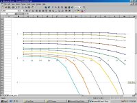
Attached are screenshots showing the Power Coefficient Table and the Revised Propeller Efficiency Table.

The thing to look for is that at no point should the efficiency be non-zero when the power coefficient is negative.
The revised Table 511 does not quite satisfy that requirement, but the overlaps are very small and hopefully transient enough not to cause problems.

The bigger issue is still that the maximum advance ratio is still too low.
Consider that with the current efficiency table, the propeller efficiency does not change above 400 MPH and I believe that some of the values there are a bit too high.

At this point, the limitations are that it is difficult to generate a smooth curve with points spaced further apart and my very limited understanding of MS Excel that I am attempting to use to generate new tables.

- Ivan.
 

Attachments

  • Record512_P-51D.jpg
    Record512_P-51D.jpg
    80.5 KB · Views: 0
  • Record511_P-51D_Revised.jpg
    Record511_P-51D_Revised.jpg
    101.1 KB · Views: 0
Back
Top